

Samsung RB195ACBP, RB197ACPN, RB197ACBP, RB197ACWP, RB215ACRS Service Manual
...
BOTTOM MOUNT FREEZER
BASIC : RB195AC/RB197AC/
RB215AC/RB217AC
MODEL NAME :
RB195ACRS RB195ACBP
RB195ACWP RB195ACPN
RB197ACRS RB197ACBP
RB197ACWP RB197ACPN
RB215ACRS RB215ACBP
RB215ACWP RB215ACPN
RB217ACRS RB217ACBP
RB217ACWP RB217ACPN
REFRIGERATOR
REFRIGERATOR CONTENTS
1. PRECAUTIONS(SAFETY WARNINGS)
2. PRODUCT SPECIFICATIONS
3. DISASSEMBLY AND REASSEMBLY
4. TROUBLESHOOTING
5. EXPLODED VIEW & PARTS LIST
6. PCB DIAGRAM
7. WIRING DIAGRAM
8. SCHEMATIC DIAGRAM
For the latest parts information, Please access to our service web site
(North America : http://service.samsungportal.com)
NW-미주향-AC 2010.6.8 3:45 PM 페이지1 i n
IMPORTANT SAFETY NOTICE
The service guide is for service men with adequate backgrounds of
electrical, electronic, and mechanical experience. Any attempt to repair
a major appliance may result in personal injury and property damage.
The manufacturer or dealer cannot be responsible for the interpretation
of this information.
SAMSUNG ELECTRONICS AMERICA, INC.
Technical Service Guide
Copyright ⓒ2010
All rights reserved. This service guide may not be reproduced in whole or in
part in any form without written permission from the SAMSUNG ELECTRONICS
Company.
WARNING
NW-미주향-AC 2010.6.8 3:45 PM 페이지2 i n

1. PRECAUTIONS(SAFETY WARNINGS)
·································4
2. PRODUCT SPECIFICATIONS
··························································
7
2-1) Introduction of Main Function ···························7
2-2) Specifications ··································8
2-3) Interior Views ··································9
2-4) Model Specification ·······························10
2-5) Model Specification &Specification Chart ······················11
2-6)Dimensions of Refrigerator (Inches) ························14
2-7) Refrigerant Route in Refrigeration cycle ······················15
2-8) Cooling Air Circulation ······························16
3. DISASSEMBLY AND REASSEMBLY
··················································
17
3-1) PRECAUTION ·································17
3-2) Refrigerator Door ································18
3-3 ) Freezer Door··································20
3-4) Freezer Door Switch·······························21
3-5) Refrigerator Light ································22
3-6) Glass shelves··································22
3-7) Moving tray···································23
3-8) Vegetable & Fruit Drawers Shelf ··························23
3-9) Gallon Door Bin ·································24
3-10) Evaporator In Refrigerator····························24
3-11) Door Handle Freezer ······························26
3-12) Freezer Light ·································26
3-13) Evaporator Cover In Freezer···························27
3-14) Evaporator InFreezer ······························27
3-15 ) Motor Fan ··································28
4. TROUBLESHOOTING
································································
30
4-1) Check items before failure diagnosis ························30
4-2) Diagnostic method according to the trouble symptom(Flow Chart) ···········42
5. EXPLODED VIEW & PARTS LIST
····················································
61
5-1) Freezer(RB217AC/RB197AC)···························61
5-2) Refrigerator(RB217AC/RB197AC)·························64
5-3) Cabinet(RB217AC/RB197AC)···························69
5-4) Disassembly of Freezer Door(RB217AC/RB197AC) ·················72
5-5) Disassembly of Refrigerator Door(RB217AC/RB197AC) ···············74
5-1) Freezer(RB215AC/RB195AC)···························76
5-2) Refrigerator(RB215AC/RB195AC)·························79
5-3) Cabinet(RB215AC/RB195AC)···························84
5-4) Disassembly of Freezer Door(RB215AC/RB195AC) ·················87
5-5) Disassembly of Refrigerator Door Left(RB215AC/RB195AC) ·············89
6. PCB DIAGRAM
····································································
91
6-1) PCB Layout with part position (Main Board)·····················91
6-2) Connector Layout with part position (Main Board) ··················92
7. WIRING DIAGRAM
··································································
93
8. SCHEMATIC DIAGRAM
······························································
94
8-1) Refrigerator Block Diagram ····························94
8-2) Power and Signal Block Diagram ·························95
8-2) MAIN ·····································96
Contents
NW-미주향-AC 2010.6.8 3:45 PM 페이지3 i n
4
1. PRECAUTIONS(SAFETY WARNINGS)
● Due to the risk of electric shock, be sure to unplug the unit before servicing.
● Use the right electronic equipment for your new Refrigerator.
Make sure to check out the right model name, rated voltage and current, operating
temperature, etc.
● Upon repair, make sure that harnesses are not to be water-penetrated and are bundled tight.
Should not be detached by a certain amount of external force.
● Upon repair, completely remove dust or other foreign substances from housing, harness,
connector, etc.
To prevent fire by tracking, short, etc.
● After repair, check out the assembled state of parts.
It should be the same as the previous state.
● Check out the surrounding conditions.
Change the location, if the fridge is located at humid, wet places or the installed state is
unstable.
● If needed, ground the fridge.
Especially, if there is a possibility of electric leakage, ground is indispensable.
● Do not allow consumers to overload a certain outlet.
● Check out whether the power cord or the outlet is broken, squeezed, chopped off or heat-
deformed.
Repair or replace the defective power cord/outlet immediately.
Make sure the power cord is not punctuated or stomped down.
● Do not allow consumers to keep food unstable or place bottles in the Freezer Room.
● Do not allow consumers to repair the fridge for themselves.
● Do not allow consumers to keep things except for food.
Pharmaceutical, Chemical substances : These are not possible to be fine-Controlled with a
consumer fridge.
Flammable material (alcohol, benzene, ether, LPG, etc) : possibility of explosion.
NW-미주향-AC 2010.6.8 3:45 PM 페이지4 i n
5
PRECAUTIONS(SAFETY WARNINGS)
Read all instructions before repairing the product and keep to the instructions
in order to prevent danger or property damage.
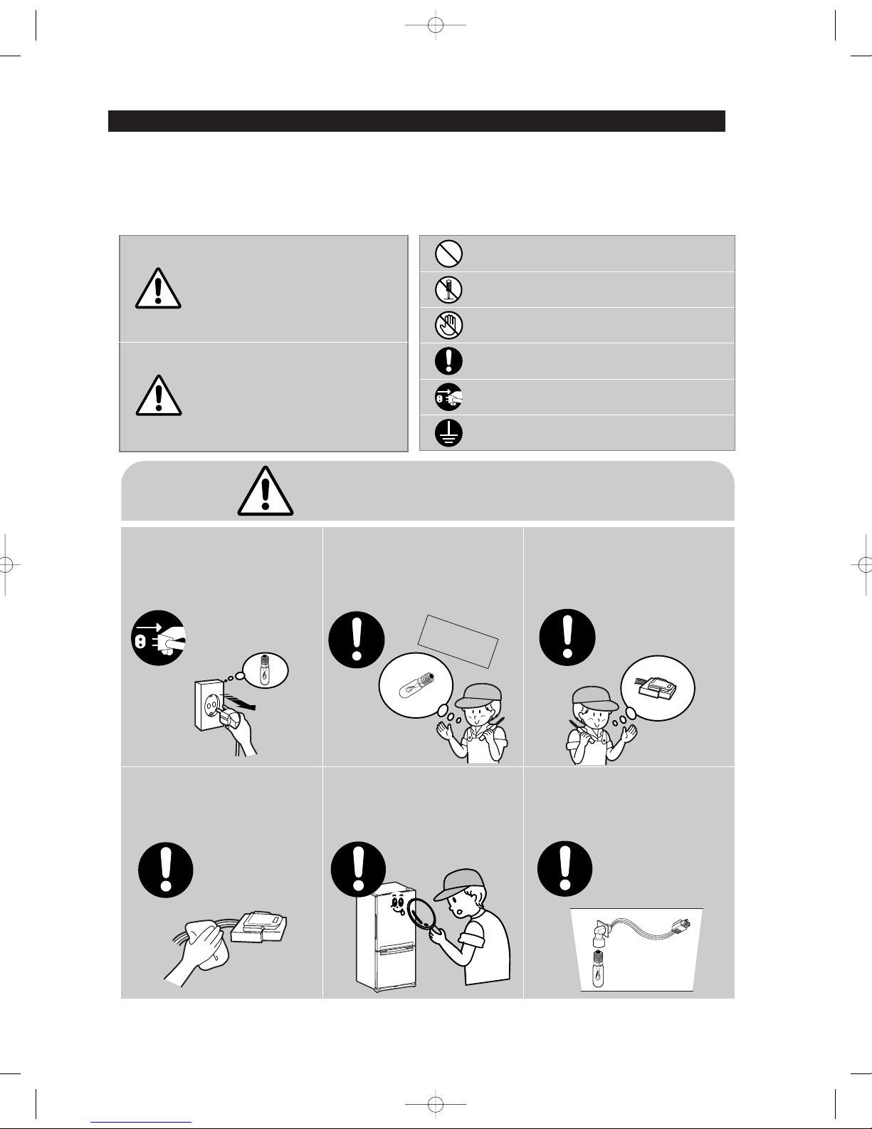
CAUTION/WARNING SYMBOLS DISPLAYED
SYMBOLS
Indicates that a
danger of death
or serious injury
exists.
Indicates that a risk
of personal injury
or material damage
exists.
means Prohibition”.
means Do not disassemble”.
means No contact”.
means The things to
be followed”.
means Earth to prevent Electric
shock”.
means Power cord should be
unplugged from the consent”
Due to risk of electric shock, be sure to
unplug the unit before servicing.
●
It may cause electric shock.
Warning
Warning & Caution
Caution
Unplug
Use the rated components on the
replacement.
●
Check the correct model, rated voltage,
rated current, operating temperature and so on.
On repair, make sure that the wires such
as harness are bundled tightly.
●
Bundle tightly wires in order not to be detached
by the external force and then not to be wetted.
Check if there is any trace indicating the
permeation of water.
●
If there is that kind of trace, change
the related components or do the necessary treatment
such as taping using the
insulating tape.
After repair, check the assembled state of
components.
●
It must be in the same assembled state
when compared with the state before disassembly.
On repair, remove completely dust or
other things of housing parts, harness
parts, and check parts.
●
Cleaning may prevent the possible fire by tracking
or short.
Rated
components
NW-미주향-AC 2010.6.8 3:45 PM 페이지5 i n
6
PRECAUTIONS(SAFETY WARNINGS)
❈
Please ler users know following warnings & cautions in detail.
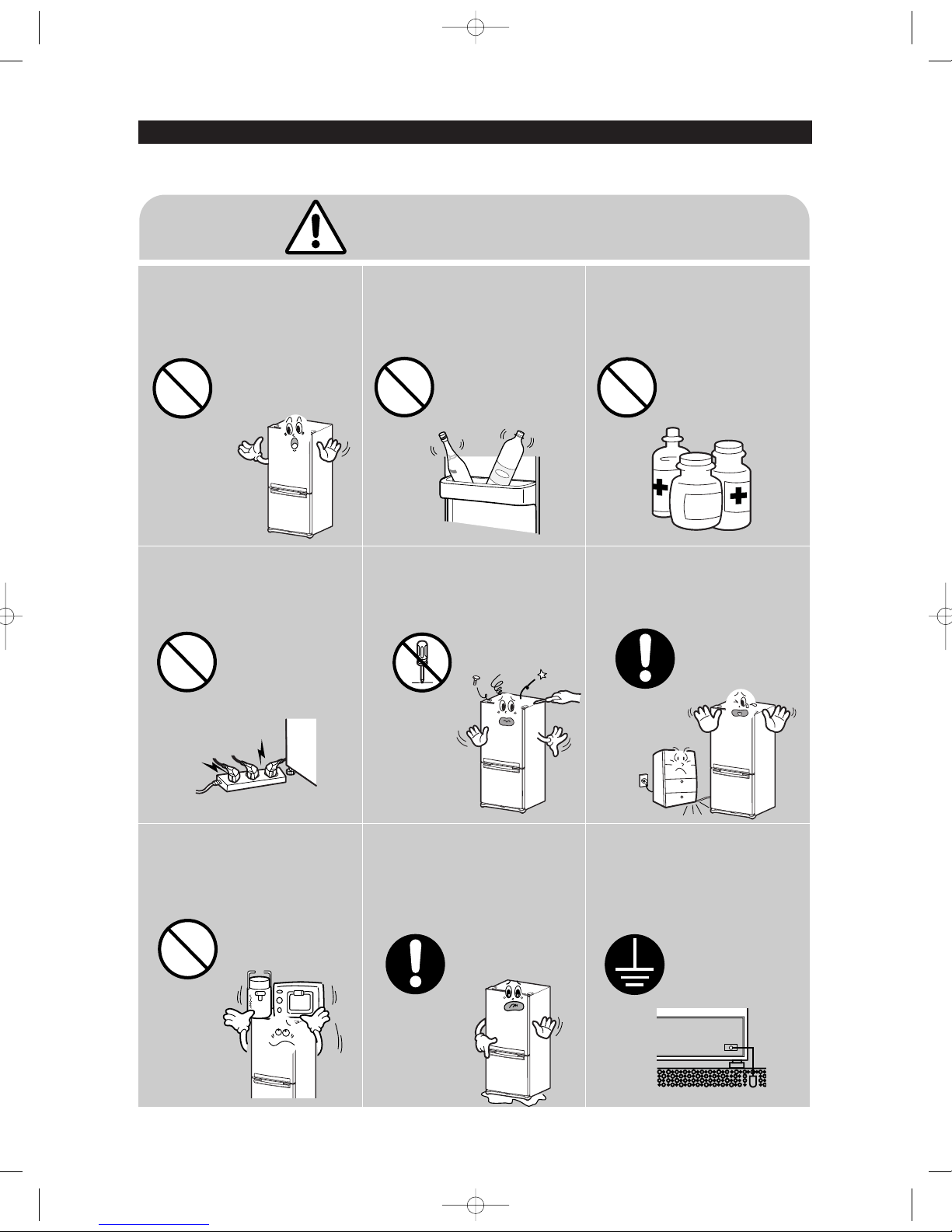
Do not allow users to put bottles or kinds of
glass in the freezer.
●
Freezing of the contents may inflict a wound.
Do not allow users to store narrow and
lengthy bottles or foods in a small multipurpose room.
●
It may hurt you when refrigerator door is
opened and closed resulting in falling
stuff down.
Do not allow users to store
pharmaceutical products, scientific
materials, etc., in the refrigerator.
●
The products which temperature
control should not be stored in
the refrigerator.
Do not allow users to store articles on the
product.
●
Opening or closing the door may cause things to
fall down, with may inflict a wound.
Prohibition
Prohibition
Prohibition
Prohibition
Warning & Caution
Do not allow users to disassemble,
repair or alter.
●
It may cause fire or abnormal operation
which leads to injury.
Do not
disassemble
Do not allow users to insert the power
plugs for many products at the same time.
●
May cause abnormal generation of heat or fire.
Prohibition
Do not allow users to bend the power
cord with excessive force or do not have
the power cord pressed by heavy article.
●
May cause fire.
Do not allow users to install the
refrigerator in the wet place or the place
which water splashes.
●
Deterioration of insulation of electric
parts may cause electric shock or fire.
The Appliance must be properly
grounded.
●
If earthing is not done, it will cause
breakdown and electric shock.
Earth
NW-미주향-AC 2010.6.8 3:45 PM 페이지6 i n

2. PRODUCT SPECIFICATIONS
●●
A newly developed SAMSUNG bottom mount freezer in 2008 has the following
characteristics.
2-1) Introduction of Main Function
7
Surround Multi Flow
●
Uniform cooling for each shelf and even in corner in
fresh food compartment by center positioned fan
and duct with multiple flow effluences.
Twin Cooling System
●
The refrigerator and the freezer have two
evaporators. Given this independent system, the
freezer and the refrigerator are cooled individually
as required and are, therefore, more efficient. Food
odor from the refrigerator does not affect food in the
freezer due to separate air flow circulation.
Moving Tray
●
The Deli Drawer can be moved side to side for
customer improved customer satisfaction.
Digital Display & Temperature Control
●
Digital Display & Temperature Control look and feel
neat & clear design.
Easy Handle System(RB197AC,RB217AC)
●
Ez-open Freezer Door
●
Ergonomic Door Design
NW-미주향-AC 2010.6.8 3:45 PM 페이지7 i n
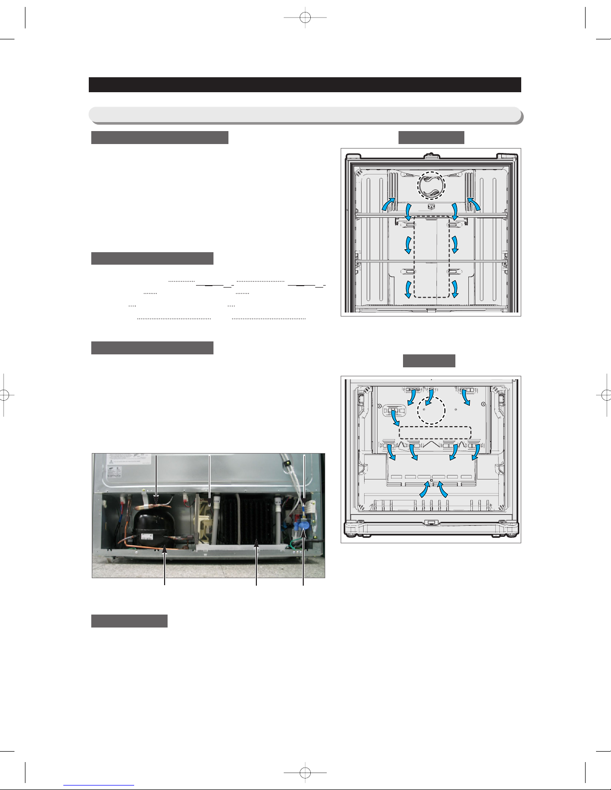
(Air inlet)(Air inlet)
Heat exchanger
Heat exchanger
Fan
(Air inlet)
Heat exchanger
Fan
(Air inlet)
Compressor
C-Fan Noise FilterDryer
condenser Water Valve
8
2-2) Specifications
PRODUCT SPECIFICATIONS
Defrost Control ···································· From 24 to 32 hrs
Thermo Bimetal Protector ··········140°F(60℃)(off) 104°F(40℃)(on)
Defrost Thermistor(502AT)
·········R : 62.6°F(12℃) F : 57.2°F(14℃)
Electrical Rating
···························AC115V 60Hz 11.6 Amps
Maximum Current Leakage·································· 0.25 mA
Maximum Ground Path Resistance··························0.1 Ohm
Energy Consumption ··································· 450kWh/year
Refrigerant Charge
···························· (R134a)5.64 oz(160g)
Compressor(MK162D-L1U)
·····················730 Btu/hr(0.124kw)
Compressor oil
···········································Freol α10c
R Capillary tube(Dia, Length)
··· 0.032
""
,118
""((00..8822mmmm,,33000000mmmm))
F Capillary tube(Dia, Length)
···· 0.032
""
,118
""((00..8822mmmm,,33000000mmmm))
Clearance must be provided for air circulation
AT TO P ··················································2
""((5500mmmm))
AT SIDES
················································1
""((2255mmmm))
AT REAR
················································2
""((5500mmmm))
Ambient Temperature 70
℉(21℃) 90℉(32℃)
Refrigerator,℉ 34℉(1℃)∼46℉(8℃)34℉(1℃)∼46℉(8℃)
Freezer,℉ -14℉(-26℃)∼8℉(-13℃) -14℉(-26℃)∼8℉(-13℃)
Run Time,% 40 60
(Air inlet)(Air inlet)
Heat exchanger
Fan
(Air inlet)(Air inlet)
Heat exchanger
ELECTRICAL SPECIFICATIONS
Freezer
Refrigerator
NO LOAD PERFORMANCE
REFRIGERATION SYSTEM
INSTALLATION
NW-미주향-AC 2010.6.8 3:46 PM 페이지8 i n
9
PRODUCT SPECIFICATIONS
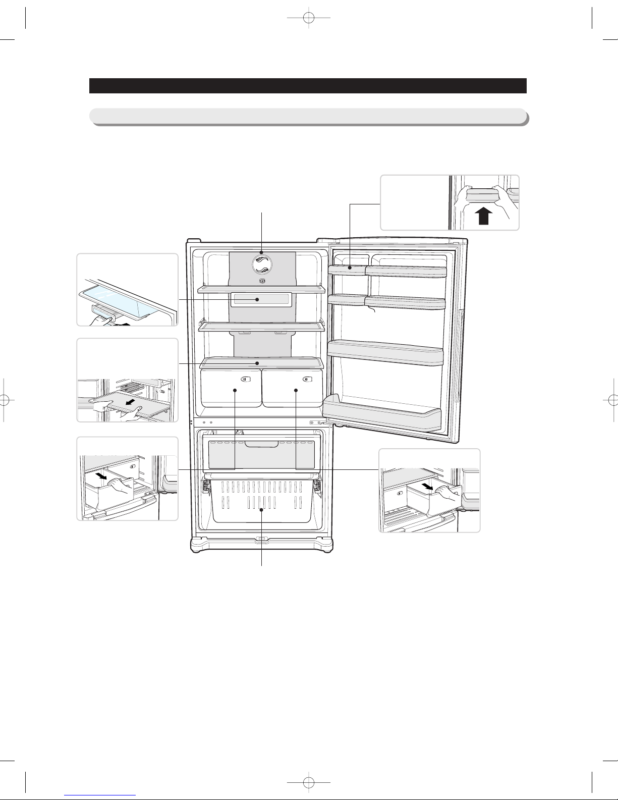
2-3)
Interior Views
Light
Freezer Drawer Bin
Door Bin
Push it up and
slide it out to
disassemble.
Deli drawer
Pull it out to disassemble.
Glass Shelf
Pull it out until its stop
Tilt down and slide it out.
Vegetable Drawer
Fruit Drawers
NW-미주향-AC 2010.6.8 3:46 PM 페이지9 i n
SAMSUNG
RB195, RB197, RB215, RB217
Twin Cooling
Contour
Cool Select Pantry
177.7
162.6
-28.6
-0.4
-22
0.4
0.5
1.3
53.6
43.5
48.2
10
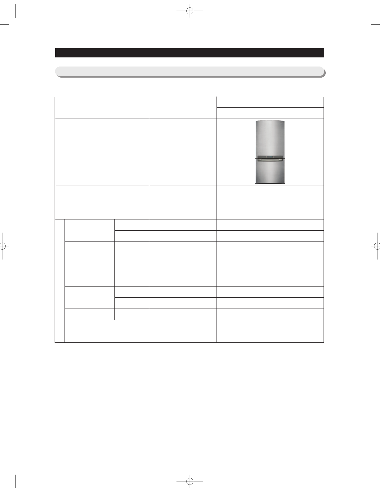
2-4) Model Specification
PRODUCT SPECIFICATIONS
F-Room
R-Room
F-Room
R-Room
F-Room
R-Room
F-Room
R-Room
N-N
Sound power level
Sound Pressure level
Cooling
Speed(Min)
Product Zone
Appearance
ITEM SPEC
89.6℉(32°C)
109.4℉(43°C)
Temperature
Distribution
(Fridge)
Run Time
Performance
Noise
Cooling Tech
Door Shape
Special Room
220↓
220↓
-26.0↓
2.0↓
-18.0↓
5.0↓
2.0↓
2.0↓
65%↓
46dB↓
45dB↓
NW-미주향-AC 2010.6.8 3:46 PM 페 이 지 1 0 i n
COLOR
11
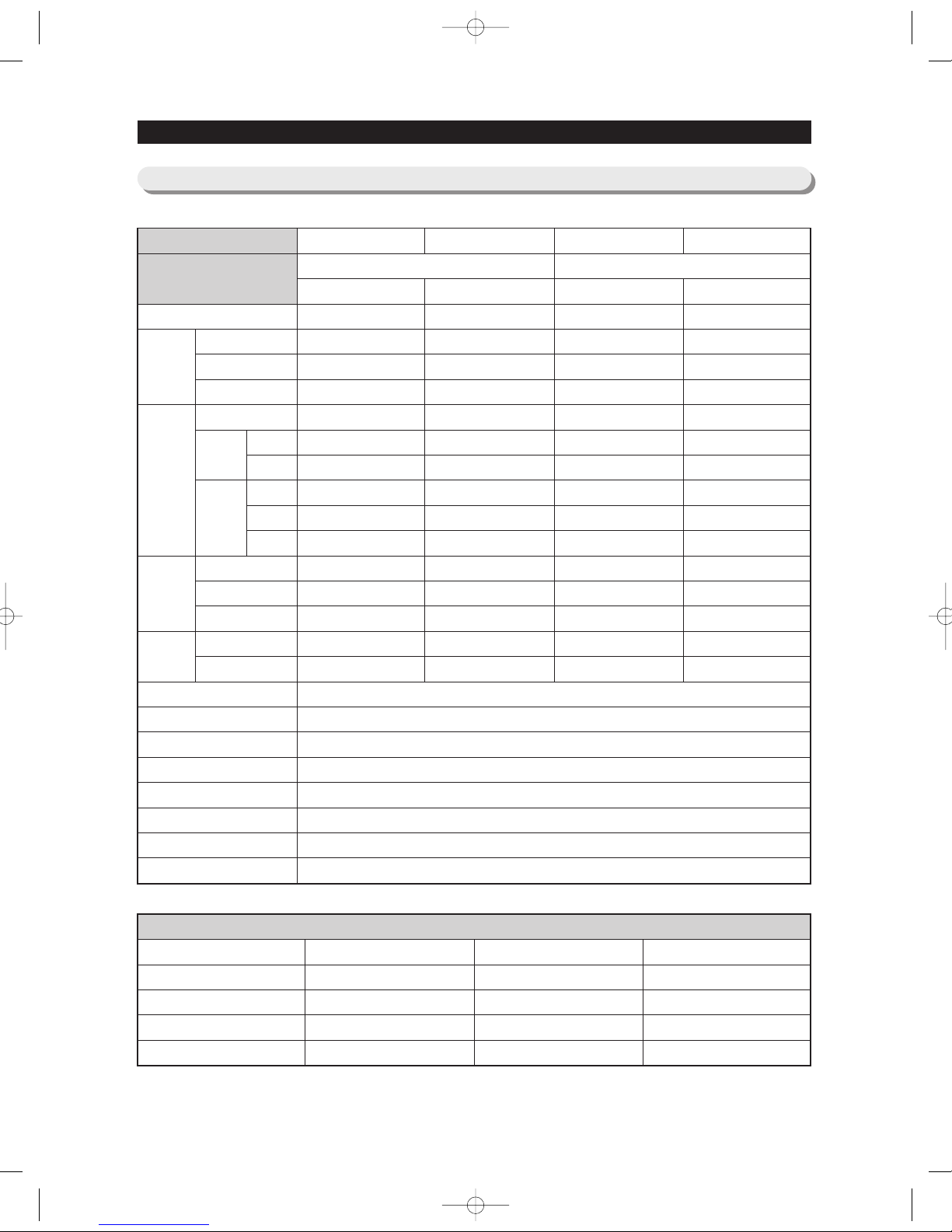
2-5) Model Specification &Specification Chart
PRODUCT SPECIFICATIONS
Black
Real STS
White
Platinum STS
Cabinet (Both Side)
All Black
Noble STS
Snow White
Noble STS
Door
Empire Black
Versailles Stainless
Snow White
Stainless Platinum
Molding
I Black
Creamy STS
Snow White
Creamy STS
Compressor
Rated Frequency and Frequency
Refrigerant
Foaming Agent
Refrigerant Input Amount
Type Refrigerator
Motor Rated Consumption Power
Electric Heater Rated Consumption Power
Free Standing Model
Dimension (WxDxH)Inch/mm
Capacity
(net)
(cu.ft/l)
Dimension
(Net :
Inch/mm)
Height
Depth
Dimension
(packing :
Inch)
Weight
(lb)
Model Number/
BOM code
Swing/No Dispenser
Swing/External Water Dispenser
Swing /No Dispenser
Swing/ External Water Dispenser
32¼x28¼x70(817x715x1778) 32¼x28¼x70(817x715x1778)32¼
x230¼x70(817x765x1778) 32¼x230¼x70(817x765x1778)
RB195 RB197 RB215 RB217
(18.7 / 529.5)
(5.9 / 167)
(12.8 / 362.5)
32 ¼/ 817
68 ¾/ 1748
70 /1778
28 ¼/ 715
28 ¼/ 715
24 ¾/ 628
34 / 865
72 ⅛/ 1832
30 ⅛/ 766
216lb (98kg)
247lb (112kg)
(18.7 / 529.5)
(5.9 / 167)
(12.8 / 362.5)
32 ¼/ 817
68 ¾/ 1748
70 /1778
28 ¼/ 715
28 ¼/ 715
24 ¾/ 628
34 / 865
72 ⅛/ 1832
30 ⅛/ 766
216lb (98kg)
247lb (112kg)
(20.5 / 579.7)
(6.5 / 184.1)
(14.0 / 395.6)
32 ¼/ 817
68 ¾/ 1748
70 /1778
30 ⅛/ 765
30 ⅛/ 765
26 ¾/ 678
34 / 865
72 ⅛/ 1832
32 ⅛/ 816
225lb (102kg)
256lb (116kg)
(20.5 / 579.7)
(6.5 / 184.1)
(14.0 / 395.6)
32 ¼/ 817
68 ¾/ 1748
70 /1778
30 ⅛/ 765
30 ⅛/ 765
26 ¾/ 678
34 / 865
72 ⅛/ 1832
32 ⅛/ 816
225lb (102kg)
256lb (116kg)
Total
Refrigerator
Freezer
Width
Width
Net
Packing
Height
Depth
w/o Hinge
With Hinge
with Handle
w/o Handle
w/o Door
2 Door 2 Door
Reciprocate
AC 115V/60Hz
R 134a
C-Pentane
5.64 oz (160g)
Indirect Cooling Method Refrigerator
140W
340W
NW-미주향-AC 2010.6.8 3:46 PM 페 이 지 1 1 i n
Items
Model
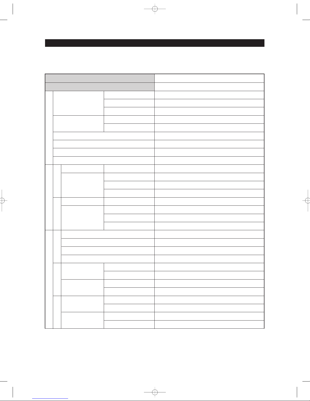
12
PRODUCT SPECIFICATIONS
Compressor
Evaporator
Model
First Defrost Cycle (Concurrent defrost of F and R)
Defrost Cycle(FRE)
Defrost Cycle(REF)
Pause time
THERMISTOR
(F-SENSOR)
502AT
Temperature Selection
-14℉(-26℃)
-2℉(-19℃)
8℉(-13℃)
Model
THERMISTOR
(R-SENSOR)
502AT
F Defrost-Sensor
R Defrost-Sensor
F Bimetal-thermo
Protector
R Bimetal-thermo
Protector
Temperature Selection
34℉(1℃)
38℉(3℃)
46℉(8℃)
Model
SPEC
Model
SPEC
Rated
Operating temperature
Rated
Operating temperature
Condenser
Dryer
Capillary tube(Dia x Length)
Refrigerant
Model
Starting type
Oil Charge
Freezer
Refrigerator
MK162DLIU-E09
AC
FREOL α-10
SPLIT FIN TYPE
SPLIT FIN TYPE
Forced and Natural Convection Type
Molecular shieve XH-9
R : 0.032” x 118” (0.82mm x 3000mm) / F : 0.032” x 118” (0.82mm x 3000mm)
R134a
6hr ±10min
12~23hr(vary according to the conditions used)
6~11hr(vary according to the conditions used)
12 ±1min
THERMISTOR (502AT)
5.0 ㏀ at 77℉(25℃)
THERMISTOR (502AT)
5.0 ㏀ at 77℉(25℃)
AC 125V 10A
Off : 140℉(60℃) / On : 104℉(40℃)
AC 125V 10A
Off : 140℉(60℃) / On : 104℉(40℃)
ON(℉)
-11℉(-24℃)
1℉(-17℃)
11℉(-12℃)
ON(℉)
36℉(2℃)
40℉(4℃)
48℉(9℃)
OFF(℉)
-17℉(-27℃)
-5℉(-21℃)
5℉(-15℃)
OFF(℉)
32℉(0℃)
36℉(2℃)
44℉(7℃)
Specification
RB19*,RB21
*
Components for FreezerDefrost Related Components
FreezerRefrigerator
Defrost Cycle
Defrost SensorBimetal
Room Temperature Sensor Components
NW-미주향-AC 2010.6.8 3:46 PM 페 이 지 1 2 i n
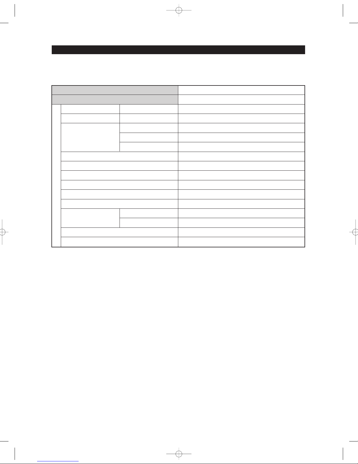
13
PRODUCT SPECIFICATIONS
Items
Model
Defrost Heater(FRE)
Defrost Heater(REF)
Over Load Relay
Rated Voltage
Motor-BLDC(FRE)
Motor-BLDC(REF)
Motor-BLDC(CIRCUIT)
Lamp(FRE)
Lamp(REF)
Heated at F Defrost
Heated at R Defrost
Model
Temp.ON
Temp.OFF
Door Switch
FRE
REF
Power Cord
Ground Screw
Specification
RB19*,RB21
*
Electric Components
AC 120V, 240W
AC115V, 120W
4TM412SFBYY-53
275 ± 41°F(135±5°C)
141.8 ± 61°F(61±9°C)
AC 115V/ 60Hz
DC12V / DREP5020LC
DC12V / DREP5020LC
DC12V / DREP5130LA
DC12V / 100mA~140mA(1EA)
DC12V / 260mA~340mA(1EA)
DC200V 0.5A / MS-406-SS-01(1EA)
DC200V 0.5A / MS-406-SS-01(1EA)
AC125V 15A
BSBN (BRASS SCREW)
NW-미주향-AC 2010.6.8 3:46 PM 페 이 지 1 3 i n
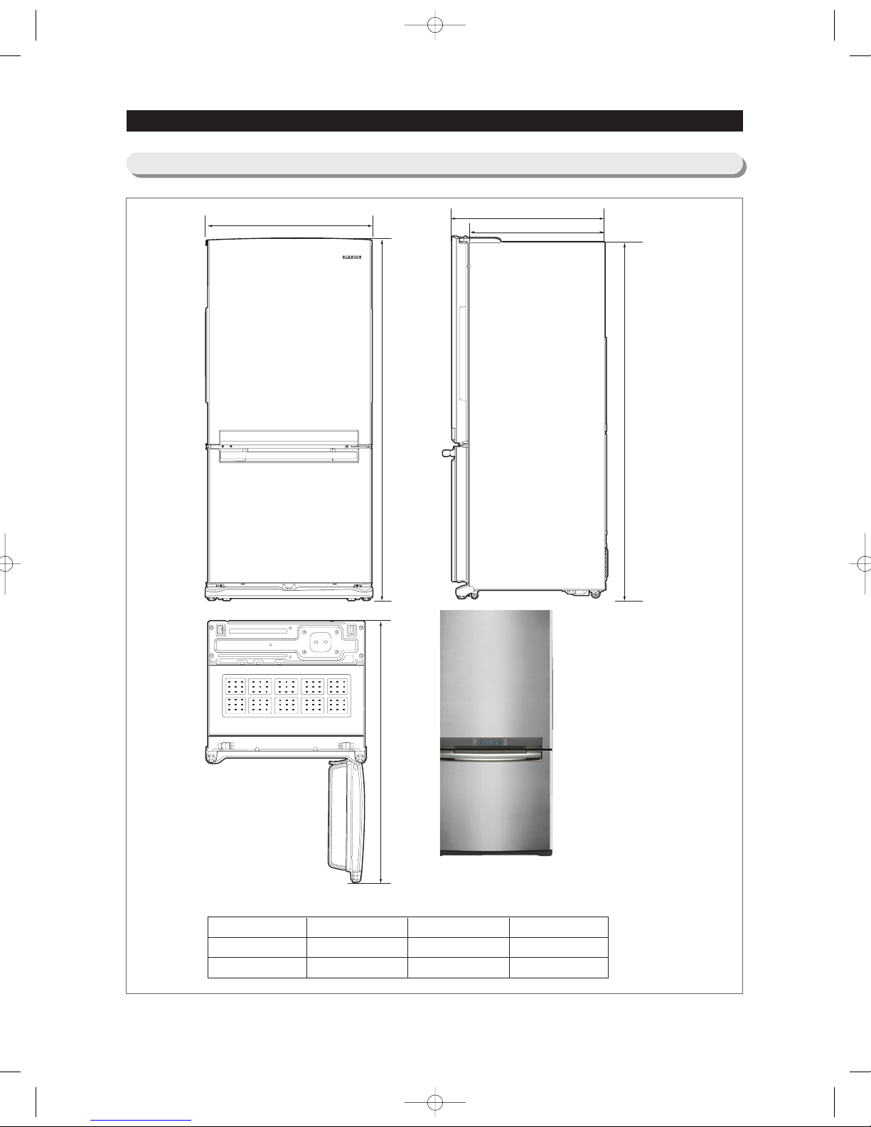
MODEL
RB19
*
RB21
*
A
24 1/4
26 1/4
B
27 5/8
29 5/8
C
57 1/2
59 1/2
14
PRODUCT SPECIFICATIONS
C
B
A
70
69 3/4
32 1/4
2-6)Dimensions of Refrigerator (Inches)
NW-미주향-AC 2010.6.8 3:46 PM 페 이 지 1 4 i n
15
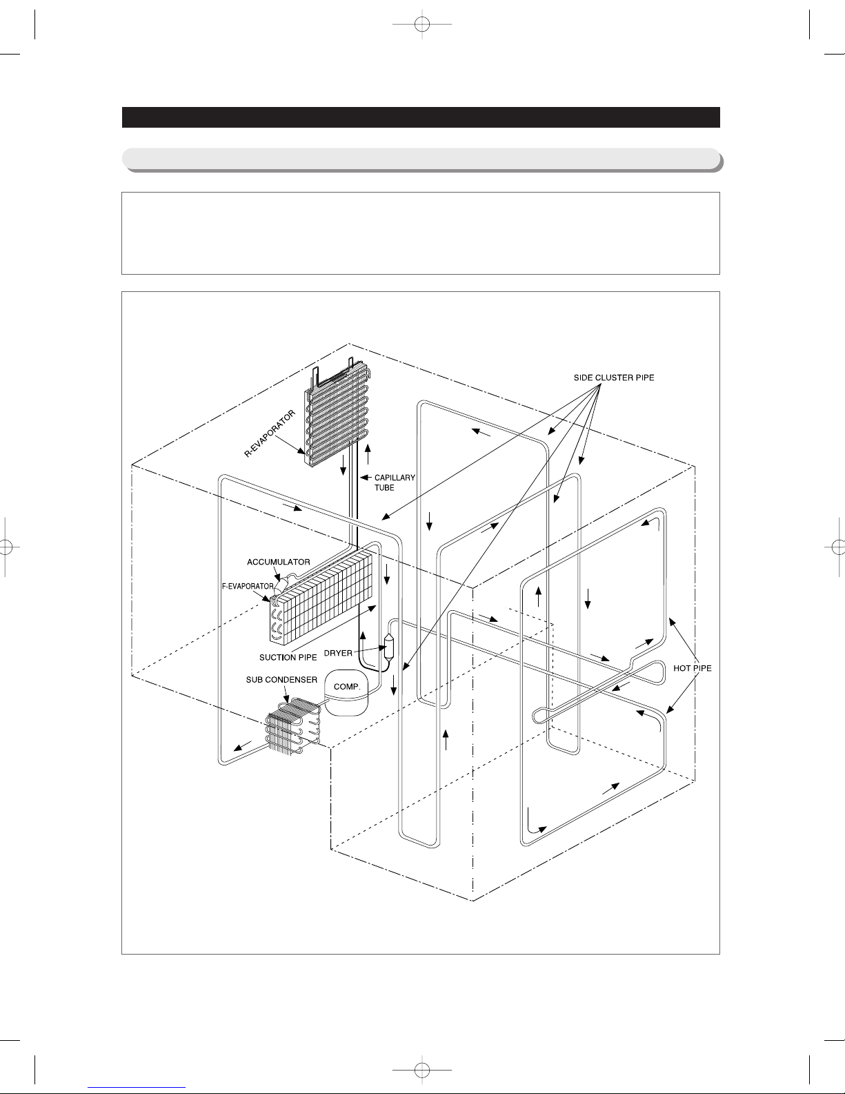
Compressor → Sub-condenser → Side Cluster → Hot Pipe → Dryer → R Capillary
→ R Evaporator → F Evaporator → Suction Pipe → Compressor
PRODUCT SPECIFICATIONS
2-7) Refrigerant Route in Refrigeration cycle
NW-미주향-AC 2010.6.8 3:46 PM 페 이 지 1 5 i n
16
PRODUCT SPECIFICATIONS
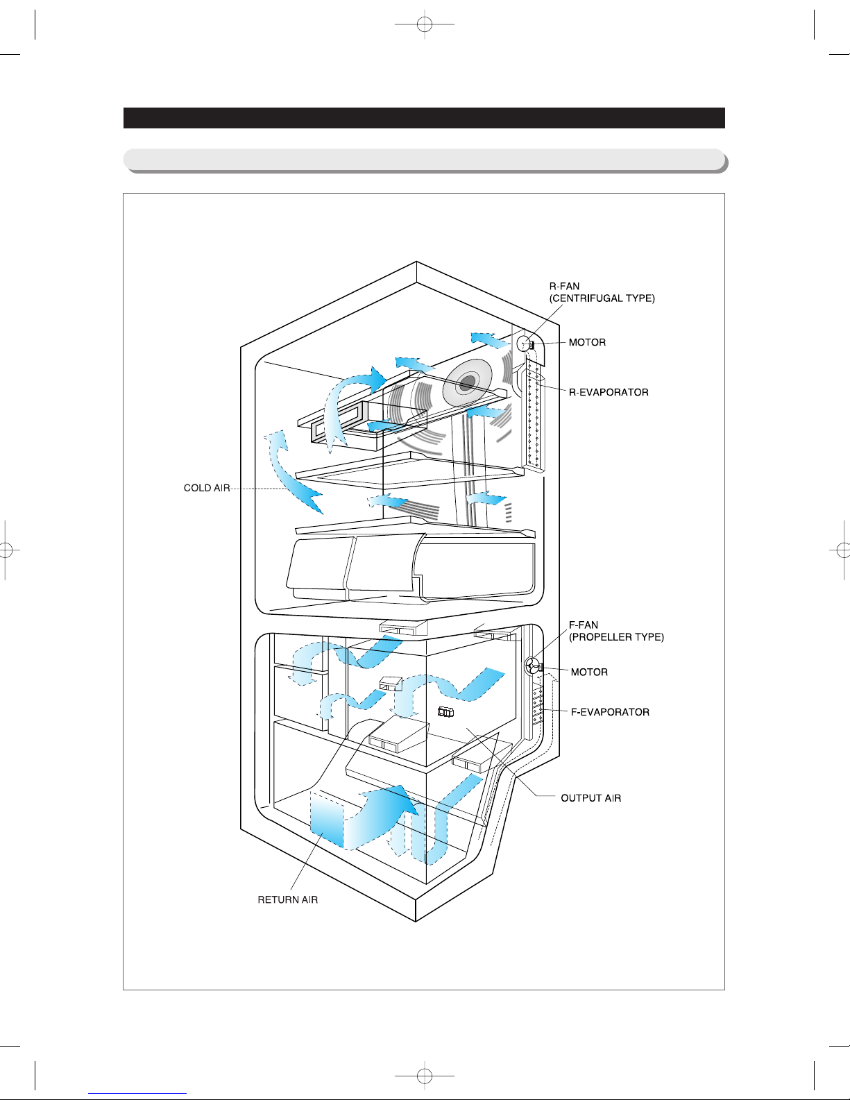
2-8) Cooling Air Circulation
NW-미주향-AC 2010.6.8 3:46 PM 페 이 지 1 6 i n
17
3. DISASSEMBLY AND REASSEMBLY
• Unplug the refrigerator before cleaning and making repairs.
• Do not dissemble or repair the refrigerator by yourself.
- It may cause risk of causing a fire, malfunction and/or personal injury.
• Remove any foreign matter or dust from the power plug pins.
- Otherwise there is a risk of fire.
• Do not use a cord that shows cracks or abrasion damage along its length or at either end.
• Do not plug several appliances into the same multiple power board. The refrigerator should always be
plugged into its own individual electrical which has a voltage rating that matched the rating plate.
- This provides the best performance and also prevents overloading house wiring circuits, which could
cause a fire hazard from overheated wires.
• Do not install the refrigerator in a damp place or place where it may come in contact with water.
- Deteriorated insulation of electrical parts may cause an electric shock or fire.
• The refrigerator must be grounded.
- You must ground the refrigerator to prevent any power leakages or electric shocks caused by current
leakage from the refrigerator.
• Do not put bottles or glass containers in the freezer.
- When the contents freeze, the glass may break and cause personal injury.
• Do not store volatile or flammable substances in the refrigerator.
- The storage of benzene, thinner, alcohol, ether, LP gas and other such products may cause
explosions.
- Required Tools
3-1) PRECAUTION
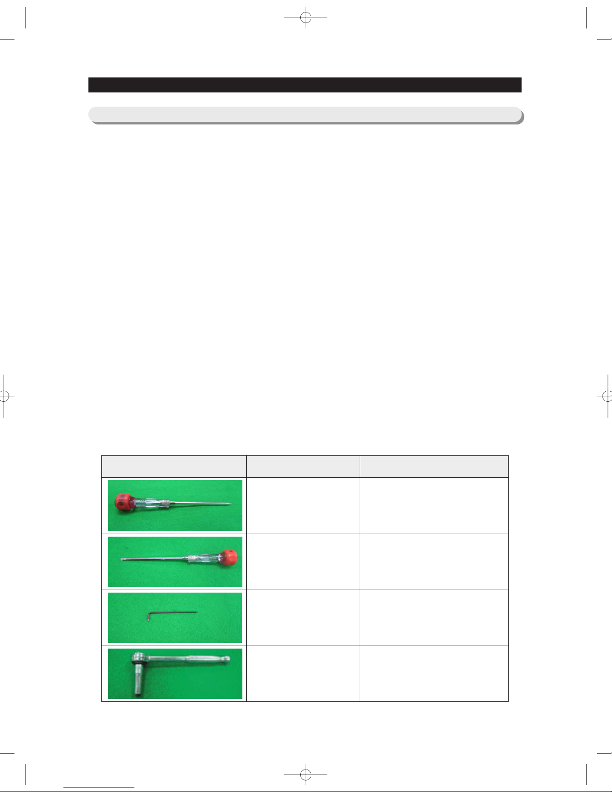
IMAGE ITEM USE
Phillips Head Driver
Use for assembling and
disassembling of screw
Flat Head Driver
Use for assembling and disassembling
of HomeBar, Dispenser, Deli
Cartessen Box, Main PBA etc...
Hex Wrench Ø2mm
Use for assembling and
disassembling of Handle
Socket Wrench Ø10mm
Use for assembling and
disassembling of Door Hinge
NW-미주향-AC 2010.6.8 3:46 PM 페 이 지 1 7 i n
18
3-2) Refrigerator Door
DISASSEMBLY AND REASSEMBLY
Refrigerator
Door
Part Name How To Do Descriptive Picture
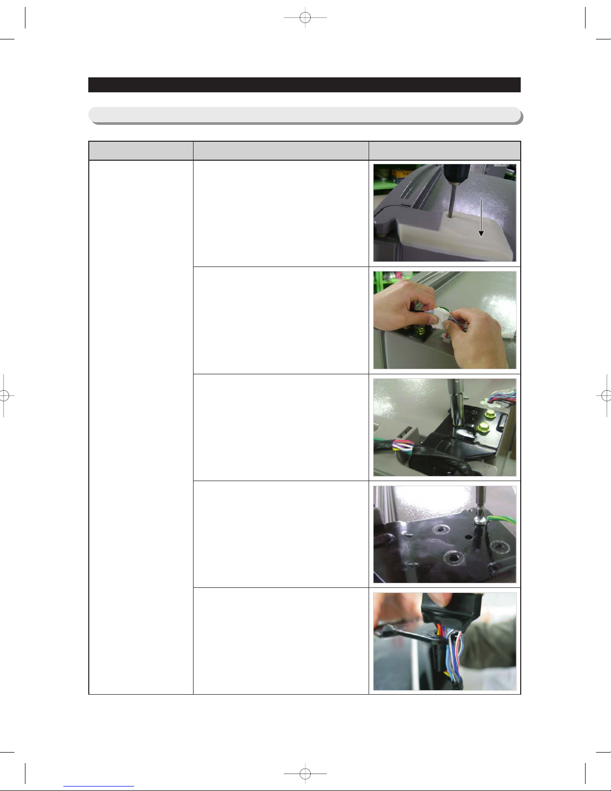
1. After removing the screw,
disassemble the Upper Right
Hinge Cover with opening door.
2. Disconnect electric wire on the
top of the refrigerator.
3. With the 7/16 inch wrench,
remove the three bolts that
holds the hinge on the top of
the refrigerator.
4. Remove the screw that hold the
ground wire.
5. Separate Hinge from electric
wire and ground wire as shown
in the picture.
Hinge Cover
Hinge CoverHinge Cover
NW-미주향-AC 2010.6.8 3:46 PM 페 이 지 1 8 i n
19
DISASSEMBLY AND REASSEMBLY
Refrigerator
Door
Part Name How To Do Descriptive Picture
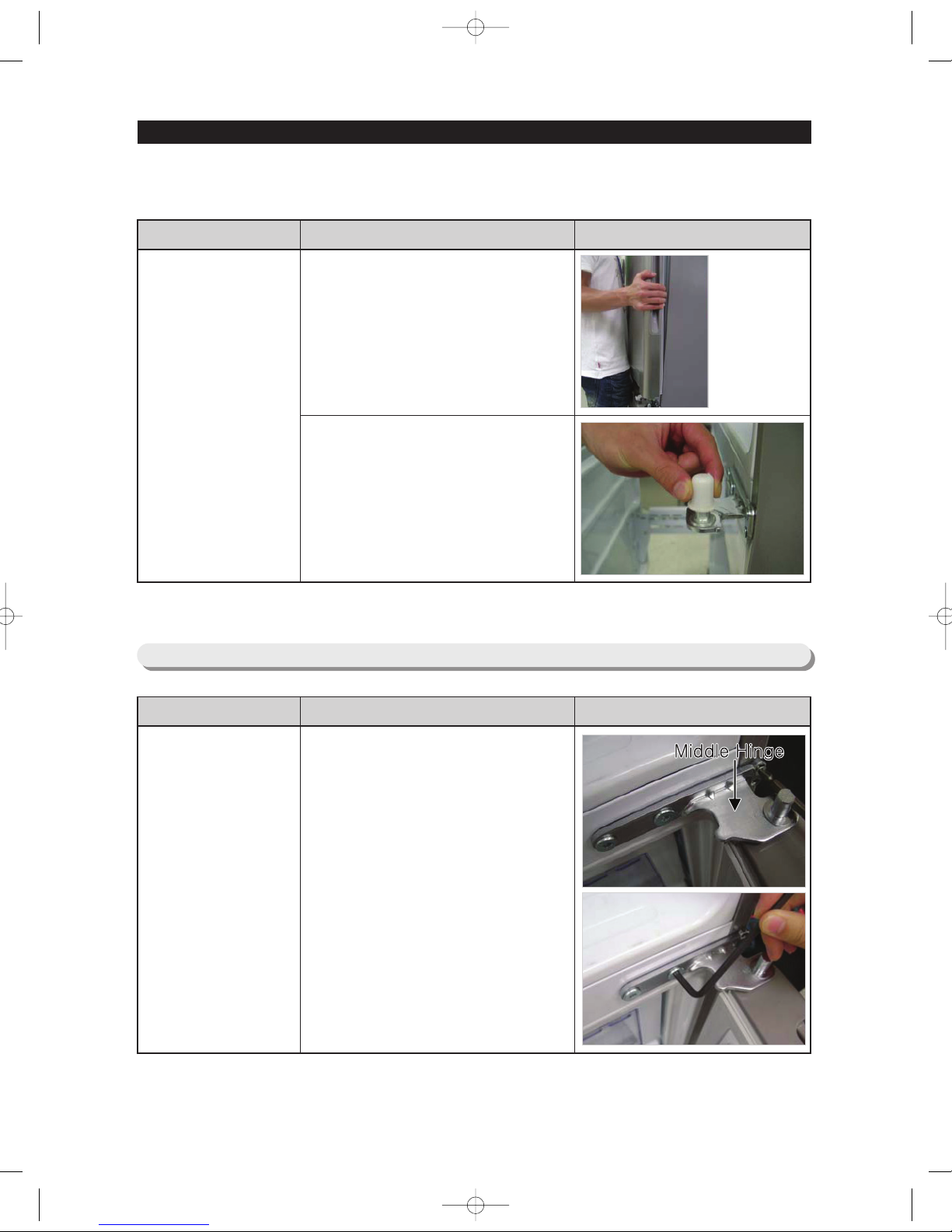
6. Disassemble the fridge door by
lifting it upward. Be careful not to
drop and scratch the fridge door.
7. Separate the Cap assembled on
the Middle Hinge.
3-3 ) Freezer Door(RB215,RB195)
Freezer Door
Part Name How To Do Descriptive Picture
1. After removing the screw and 2
special screws, disassemble
Middle Hinge.
NW-미주향-AC 2010.6.8 3:46 PM 페 이 지 1 9 i n
20
DISASSEMBLY AND REASSEMBLY
3-3 ) Freezer Door(RB215,RB195)
Part Name How To Do Descriptive Picture
Freezer Door
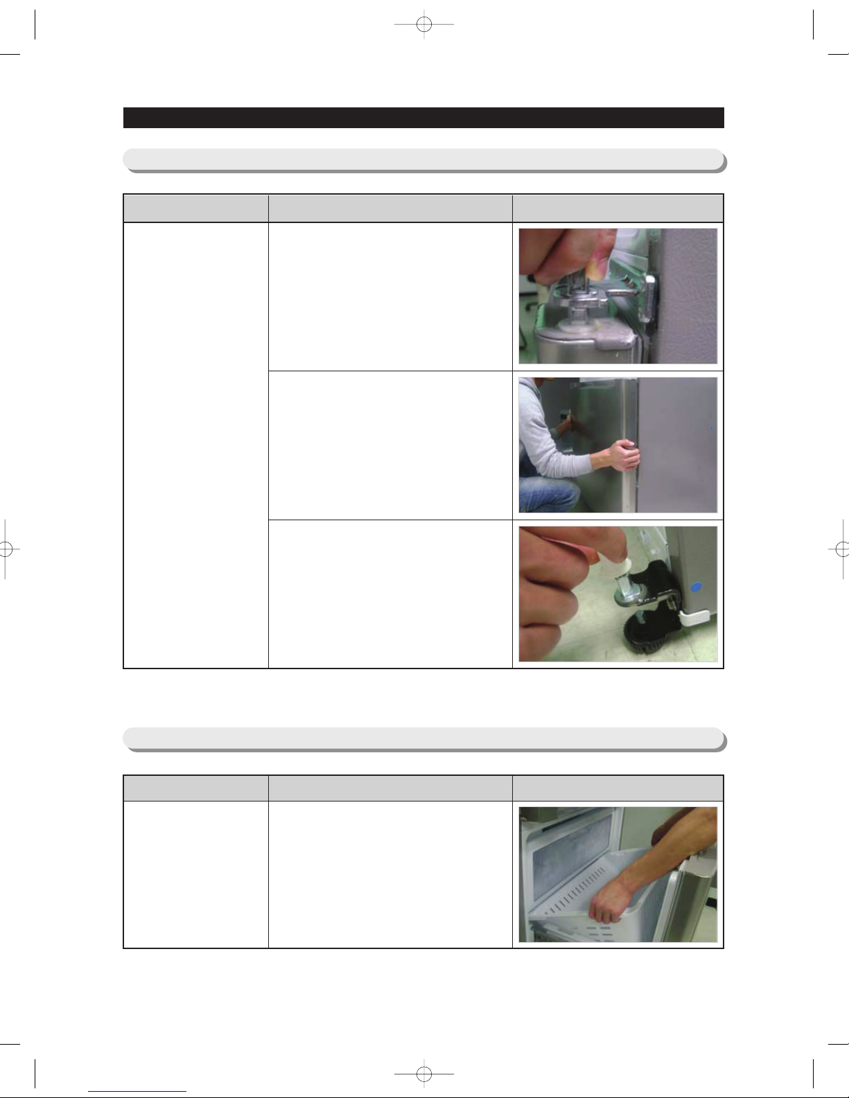
2. Remove the Middle Hinge
connected to the Freezer.
3. Disassemble the Freezer door
by lifting it upward. Be careful
not to drop and scratch the
Freezer door
4. Disassemble the Cap on the
Low Hinge.
3-3 ) Freezer Door(RB217AC,RB197AC)
Freezer
Door
Part Name How To Do Descriptive Picture
1. After opening the Freezer door,
separate drawer box
NW-미주향-AC 2010.6.8 3:46 PM 페 이 지 2 0 i n
1. Remove 1 screw at the lower
part of the Freezer.
2. Separate the Cap.
3. Separate the Housing.
21
DISASSEMBLY AND REASSEMBLY
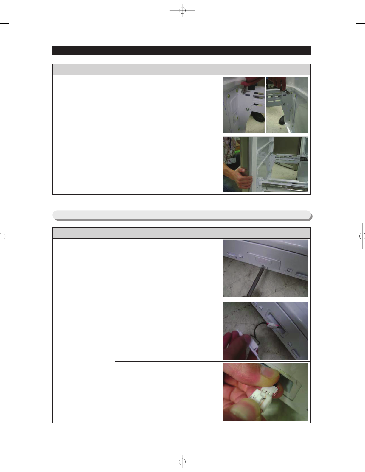
3-4) Freezer Door Switch
Freezer
Door Switch
Part Name How To Do Descriptive Picture
Freezer
Door
Part Name How To Do Descriptive Picture
2. With the 7/16 inch wrench,
remove the each two bolts
connecting rail with door.
3. Disassemble the Freezer door
from the rails.
NW-미주향-AC 2010.6.8 3:46 PM 페 이 지 2 1 i n
22
DISASSEMBLY AND REASSEMBLY
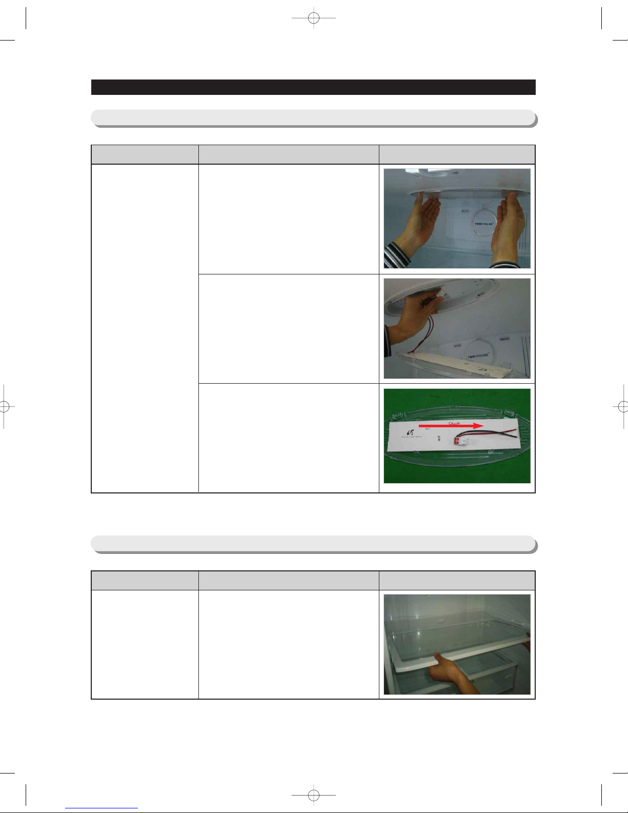
3-5) Refrigerator Light
Refrigerator Light
Part Name How To Do Descriptive Picture
1. Remove the lamp cover by
pulling it down as pushing the
rear of lamp cover.
2. Separate the LED panel.
3. Remove the LED panel by lifting
the left part of LED panel while
pushing it to right. (Refer to
pictrue)
3-6) Glass shelves
Glass shelves
Part Name How To Do Descriptive Picture
1. When pulling out the shelf, if it is
not slid out well, lift it up slightly
and pull out again.
NW-미주향-AC 2010.6.8 3:46 PM 페 이 지 2 2 i n
23
DISASSEMBLY AND REASSEMBLY
3-7) Moving tray
Moving tray
Part Name How To Do Descriptive Picture
1. When pulling out the Moving
tray, if it is not slid out well, lift it
up slightly and pull out again.
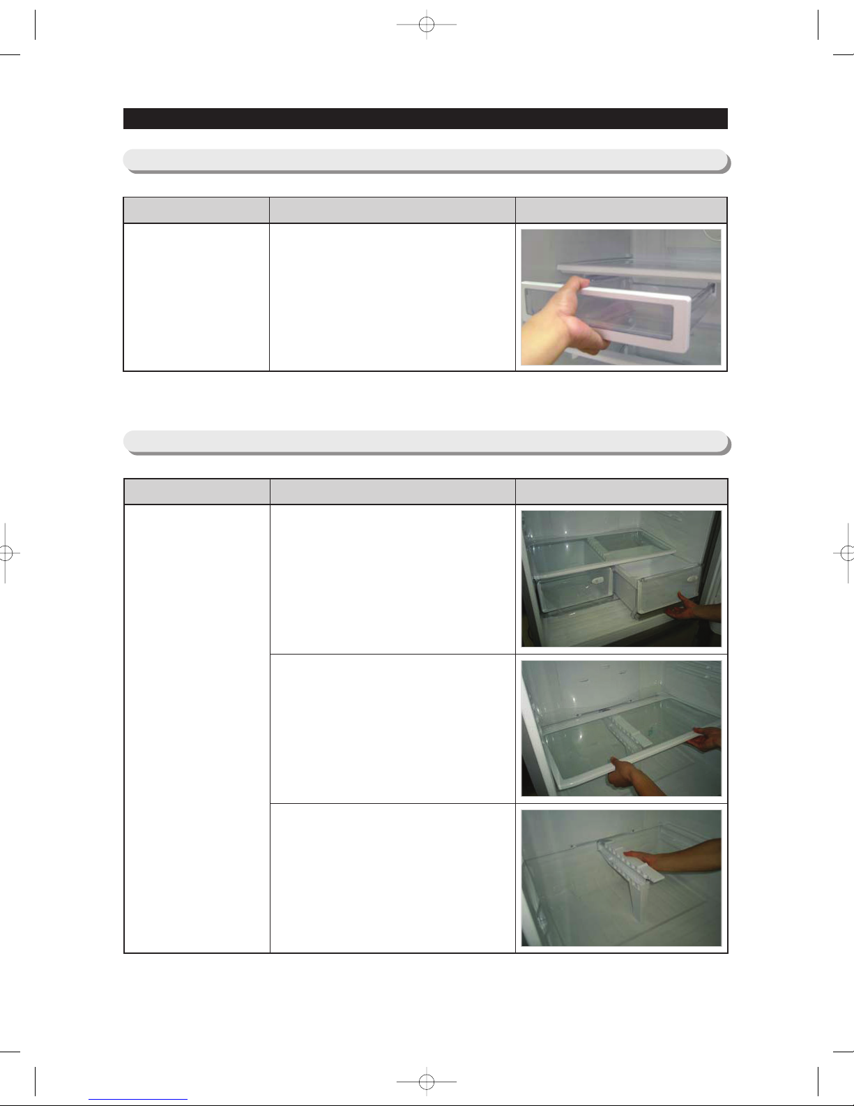
3-8) Vegetable & Fruit Drawers Shelf
Vegetable & Fruit
Drawers Shelf
Part Name How To Do Descriptive Picture
1. Remove the vegetable & fruit
drawer by pulling the roller part
and lifting it up.
2. Remove the vegetable & fruit
drawer shelf by pulling it out.
(Refer to the picture)
3. Remove the vegetable & fruit
drawer partition by pulling it out.
(Refer to the picture)
NW-미주향-AC 2010.6.8 3:46 PM 페 이 지 2 3 i n
24
DISASSEMBLY AND REASSEMBLY
3-9) Gallon Door Bin
Gallon Door Bin
Part Name How To Do Descriptive Picture
1. Remove the gallon door bin by
lifting it up. (Refer to the picture)
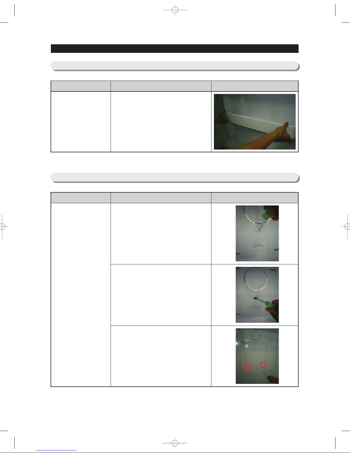
3-10) Evaporator In Refrigerator
Evaporator In
Refrigerator
Part Name How To Do Descriptive Picture
1. Remove the screw cap with a
flat-blade screwdriver.
2. Unscrew a screw.
3. Unscrew two screws. And
remove the hook by pulling it
from the lower part and pushing
the cover down. (Refer to the
picture)
NW-미주향-AC 2010.6.8 3:46 PM 페 이 지 2 4 i n
25
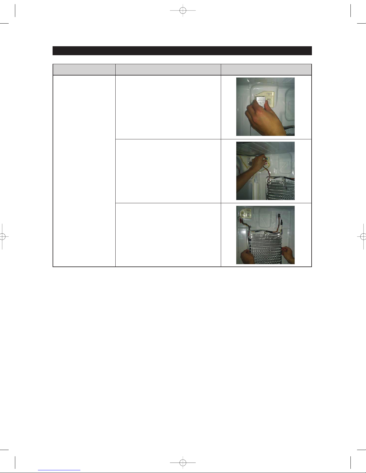
DISASSEMBLY AND REASSEMBLY
Evaporator In
Refrigerator
Part Name How To Do Descriptive Picture
4. Remove the housing cover by
pushing both lateral sides of the
housing cover and pulling it out.
(Refer to the picture)
5. Disconnect the housing
connector part. (Refer to the
picture)
6. Remove the evaporator by
Lifting the bottom side of it up
and pulling it out. (Refer to the
picture)
NW-미주향-AC 2010.6.8 3:46 PM 페 이 지 2 5 i n

26
DISASSEMBLY AND REASSEMBLY
3-11) Door Handle Freezer
Door Handle
Freezer
Part Name How To Do Descriptive Picture
1. Remove the Cap Door with a
flat-blade(-) screwdriver.
2. Lift the handle up with force in
the direction of arrow.
3-12) Freezer Light
Freezer Light
Part Name How To Do Descriptive Picture
1. Remove the lamp cover by
pushing the hook of lamp cover.
2. Remove the LED panel by lifting
the left part of LED panel while
pushing it to right. (Refer to
pictrue)
NW-미주향-AC 2010.6.8 3:47 PM 페 이 지 2 6 i n
27
DISASSEMBLY AND REASSEMBLY
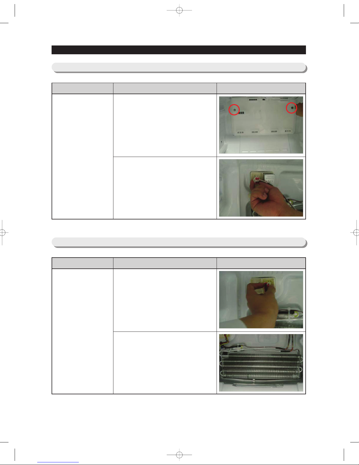
3-13) Evaporator Cover In Freezer
Evaporator Cover
In Freezer
Part Name How To Do Descriptive Picture
1. Remove the freezer door and
freezer drawer by pulling out the
drawer and then unscrewing 2
screws. Lift up the evaporator
cover.
2. Disengage the housing
connector and remove the
evaporator cover.
3-14) Evaporator InFreezer
Evaporator In
Freezer
Part Name How To Do Descriptive Picture
1. Remove the housing cover by
pushing both lateral sides of
housing cover part and pulling it
out. Remove the housing
connector part.
2. Remove the evaporator by
pulling the lower part of the
evaporator while lifting it up.
NW-미주향-AC 2010.6.8 3:47 PM 페 이 지 2 7 i n
28
DISASSEMBLY AND REASSEMBLY
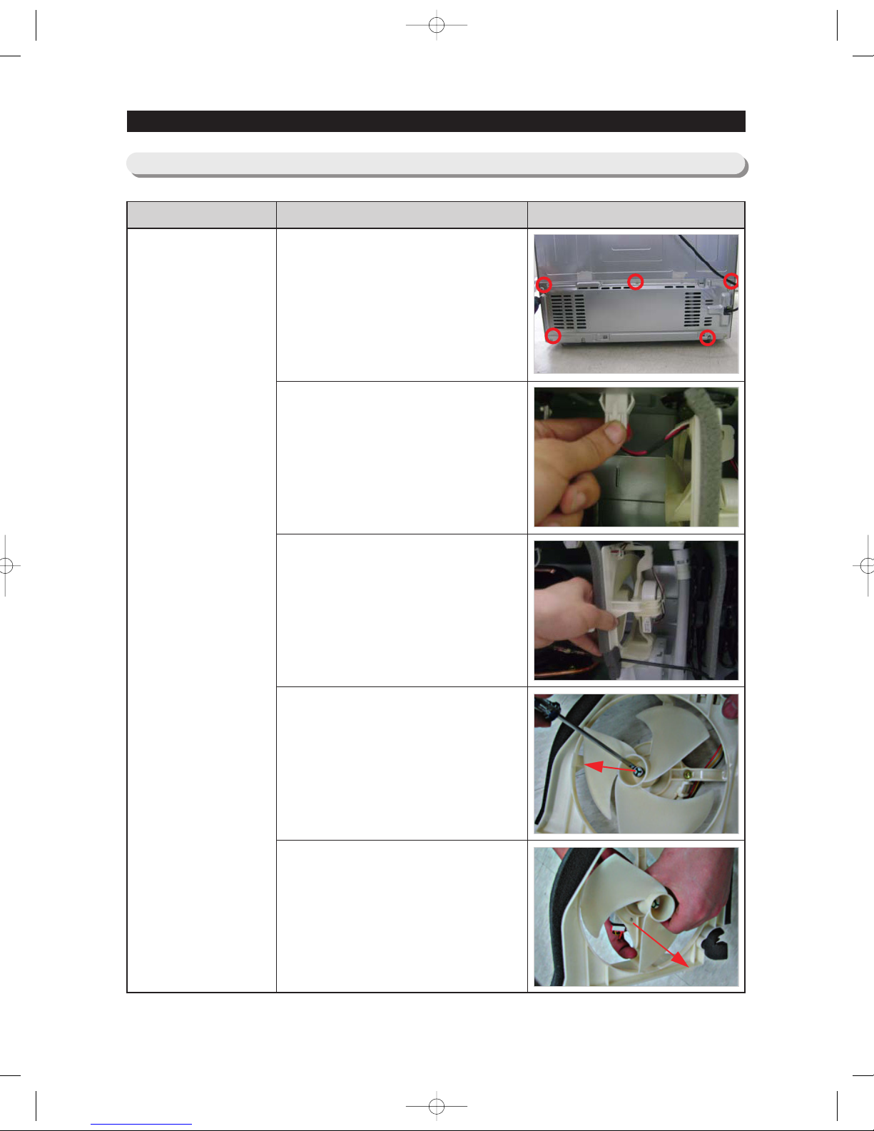
3-15 ) Motor Fan
Motor Fan
Part Name How To Do Descriptive Picture
1. Unscrew 5 screws of cover
compressor.
2. Disengage the housing
connector. (Refer to the picture)
3. Remove the hooker of support
circuit motor by lifting the hooker
up and pulling it out.
4. Remove the screw with a flatblade screwdriver. (Refer to the
picture)
5. Remove the motor fan by pulling
the fan out while graping the
motor part.(Refer to the picture)
NW-미주향-AC 2010.6.8 3:47 PM 페 이 지 2 8 i n
29
DISASSEMBLY AND REASSEMBLY
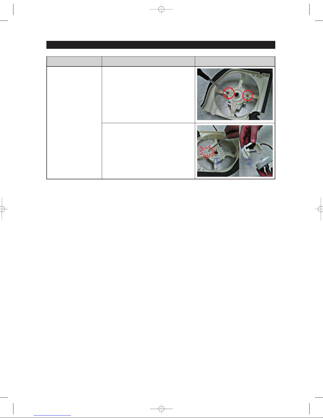
Motor Fan
Part Name How To Do Descriptive Picture
6. Unscrew 2 screws fixed in the
motor.
7. Remove the hook of the motor
cover with a flat-blade (-)
screwdriver and then remove the
motor.
NW-미주향-AC 2010.6.8 3:47 PM 페 이 지 2 9 i n
30
4. TROUBLESHOOTING
4-1) Check items before failure diagnosis
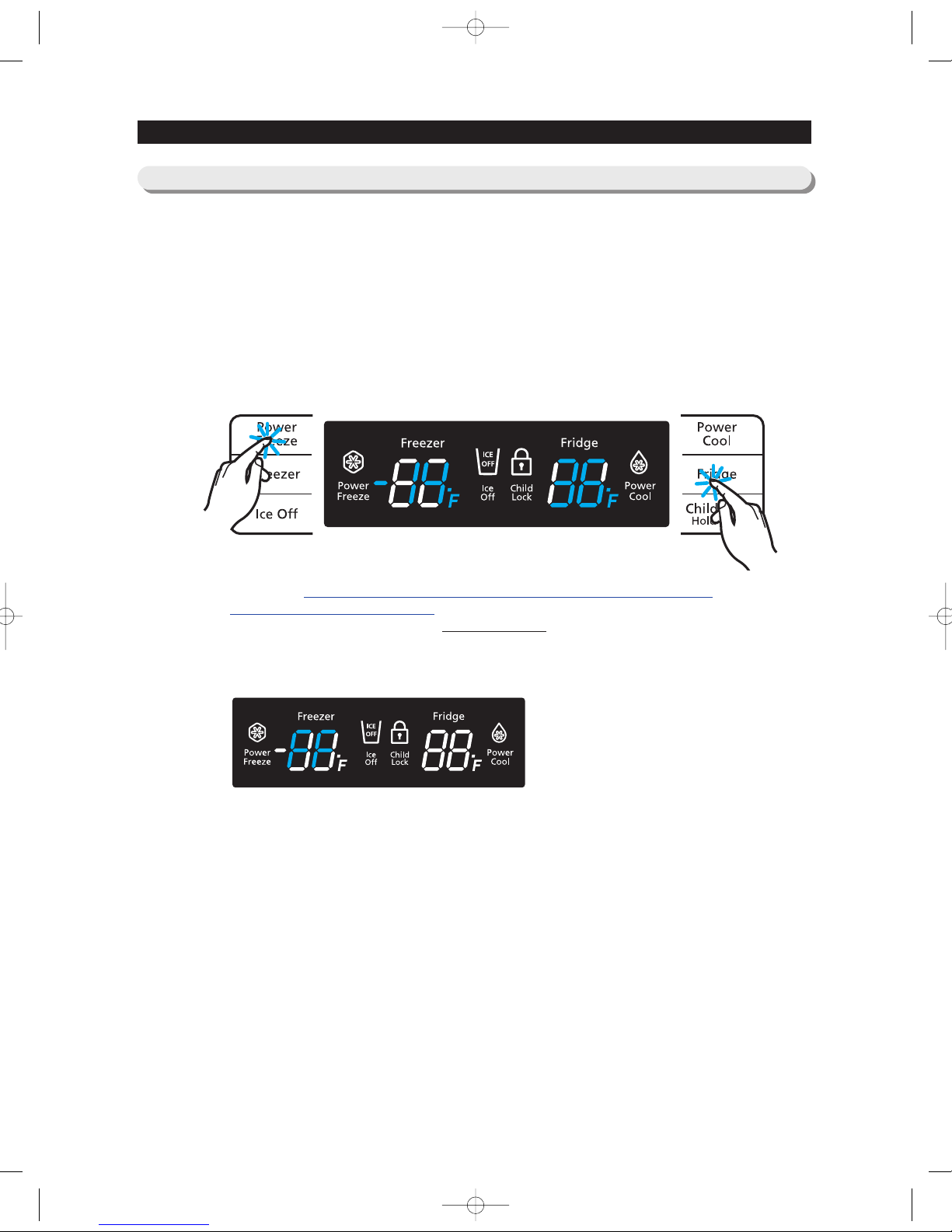
4-1-1. TEST mode (Manual operation / Manual defrost function)
●
If the Power Freeze and Fridge Key on the front panel are pressed simultaneously for 8 seconds, it will be
changed to the Test Mode and all display on the front panel will be off.
●
If any key on the front panel is pressed within 15 seconds after changing to Test Mode, it will be operated as
below sequence; Manual operation (FF) → Manual defrost of R (rd) → Manual defrost of F/R (Fd) → Cancel
(Display all off).
●
If any key on the front of panel is not pressed within 15 seconds after the Test Mode, the Test Mode will be
canceled and it will be returned to previous mode.
① If Power Freeze Key + Fridge Key are pressed simultaneously for 8
seconds and all displays are off, it will be changed to the Test Mode (manual operation)
pressing any key.
1-1) If any key is pressed once in TEST MODE, "FF" blinks on the display and it indicates the
refrigerator has entered the manual operation. At this moment, buzzer beeps as an alarm.
1-2) If manual function is selected, compressor will run at once without 5 minutes delay in any mode. If
the refrigerator is on the defrost cycle at the moment, defrost will be stopped and manual operation
will begin. (Be careful, if manual operation gets started immediately at the moment of compressor
off, overload could be occurred.)
1-3) If manual operation works, compressor & F-FAN operate continuously for 24 hours and fresh food
compartment will be controlled by the setting temperature.
1-4) When the manual operation runs, setting temperature will be selected automatically as below ;
Freezer compartment -14℉(-25℃), Fresh food compartment 32℉(1℃).
1-5) During manual operation Power Freeze & Power Cool function will not be worked. If a function is
selected, the power function icon of the selected one will be off automatically after 10 seconds.
1-6) Manual operation can be canceled during manual operation by turning on the appliance after
power off(resest) or choosing the following step 4) test cancel mode.
1-7) When the manual operation runs, alarm (0.25 seconds ON/0.75 seconds OFF) will beep
continuously until manual operation is completed and there is no function to make the sound stop.
1) Manual operation function
❶
❷
NW-미주향-AC 2010.6.8 3:47 PM 페 이 지 3 0 i n
 Loading...