


Home Page |
|
Table of Contents |
|
|
|
OfficeServTM 7100
General Description
Every effort has been made to eliminate errors and ambiguities in the information contained in this booklet. Any questions concerning information presented here should be directed to SAMSUNG TELECOMMUNICATIONS AMERICA. SAMSUNG TELECOMMUNICATIONS AMERICA disclaims all liabilities for damages arising from erroneous interpretation or use of information presented in this manual.

Home Page |
|
Table of Contents |
|
|
|
Publication Information
SAMSUNG TELECOMMUNICATIONS AMERICA reserves the right without prior notice to revise information in this publication for any reason.
SAMSUNG TELECOMMUNICATIONS AMERICA also reserves the right without prior notice to make changes in design or components of equipment as engineering and manufacturing may warrant.
Copyright 2007
Samsung Telecommunications America
All rights reserved. No part of this manual may be reproduced in any form or by any means— graphic, electronic or mechanical, including recording, taping, photocopying or information retrieval systems—without express written permission of the publisher of this material.
PRINTED IN USA |
04/07 |

Home Page |
|
Table of Contents |
|
|
|
TABLE OF CONTENTS
PART |
DESCRIPTION |
PAGE |
|||||||||||||
1 |
SYSTEM OVERVIEW |
|
|||||||||||||
|
1.1 |
GENERAL DESCRIPTION .......................................................................................................................... |
1.1 |
||||||||||||
|
1.2 |
|
|
|
|
|
|
|
|
|
|
|
|
|
|
|
SIZE AND CONFIGURATION .................................................................................................................. |
1.3 |
|||||||||||||
|
1.3 |
TECHNOLOGY ............................................................................................................................................ |
1.6 |
||||||||||||
|
1.4 |
PROGRAMMING ........................................................................................................................................ |
1.6 |
||||||||||||
|
|
|
|
|
|
|
|
|
|
|
|
|
|
||
|
1.5 MIGRATION TO OFFICESERV 7200 OR OFFICESERV 7400 |
............................................................1.6 |
|||||||||||||
|
|
|
|
|
|
|
|
|
|
|
|
|
|
||
2 |
HARDWARE DESCRIPTIONS |
|
|||||||||||||
|
2.1 |
SYSTEM CABINET ...................................................................................................................................... |
2.1 |
||||||||||||
|
2.2 |
PROCESSOR CARDS .................................................................................................................................. |
2.1 |
||||||||||||
|
|
|
|
|
|
|
|
|
|
|
|
|
|
||
|
|
2.2.1 |
|
EMBEDDED APPLICATIONS ...................................................................................................... |
2.1 |
||||||||||
|
|
2.2.2 MULTIMEDIA PLUS CARD .......................................................................................................... |
2.2 |
||||||||||||
|
2.3 |
INTERFACE CARDS .................................................................................................................................... |
2.2 |
||||||||||||
|
2.4 |
|
|
|
|
|
|
|
|
|
|
|
|||
|
DAUGHTERBOARD CARDS .................................................................................................................... |
2.2 |
|||||||||||||
|
2.5 OFFICESERV 7200/OFFICESERV 7400 TRUNK CARDS .................................................................. |
2.4 |
|||||||||||||
|
|
|
|
|
|
|
|
|
|
|
|
||||
|
2.6 OFFICESERV 7200/OFFICESERV 7400 VoIP CARDS ........................................................................ |
2.4 |
|||||||||||||
|
|
|
|
|
|
|
|
|
|
|
|
||||
|
2.7 OFFICESERV 7200/OFFICESERV 7400 STATION CARDS................................................................ |
2.4 |
|||||||||||||
|
|
|
|
|
|
|
|
|
|
|
|
||||
|
2.8 |
STATION EQUIPMENT .............................................................................................................................. |
2.6 |
||||||||||||
|
|
2.8.1 DS 5000 SERIES EQUIPMENT .................................................................................................... |
2.6 |
||||||||||||
|
|
2.8.2 |
|
iDCS SERIES EQUIPMENT .......................................................................................................... |
2.8 |
||||||||||
|
|
2.8.3 OFFICESERV™ ITP-5100 SERIES EQUIPMENT.................................................................... |
2.11 |
||||||||||||
|
|
2.8.4 |
|
OFFICESERV™ SOFTPHONE.................................................................................................... |
2.12 |
||||||||||
|
|
2.8.5 |
|
OFFICESERV™ WIRELESS.......................................................................................................... |
2.12 |
||||||||||
3 |
SPECIFICATIONS |
|
|||||||||||||
|
3.1 |
ELECTRICAL SPECIFICATIONS................................................................................................................ |
3.1 |
||||||||||||
|
|
|
|
|
|
|
|
|
|
|
|
||||
|
|
3.1a I/O VOLTAGE OF PSU .................................................................................................................... |
3.1 |
||||||||||||
|
|
|
|
|
|
|
|
|
|
|
|||||
|
3.2 |
DIMENSIONS................................................................................................................................................ |
3.1 |
||||||||||||
|
3.3 |
ENVIRONMENTAL LIMITS ........................................................................................................................ |
3.2 |
||||||||||||
|
|
|
|
|
|
|
|
|
|||||||
|
3.4 |
CABLE REQUIREMENTS............................................................................................................................ |
3.2 |
||||||||||||
|
|
|
|
|
|
|
|
||||||||
|
3.5 |
RING AND TONES ...................................................................................................................................... |
3.2 |
||||||||||||
|
|
3.5.1 RING CYCLES.................................................................................................................................... |
3.2 |
||||||||||||
|
|
3.5.1a SYSTEM RING CYCLES ................................................................................................................ |
3.2 |
||||||||||||
|
|
3.5.2 RING .................................................................................................................................................... |
3.3 |
||||||||||||
|
|
3.5.3 SYSTEM TONES .............................................................................................................................. |
3.3 |
||||||||||||
|
3.6 |
KEYSET LED INDICATIONS ...................................................................................................................... |
3.3 |
||||||||||||
|
|
|
|
|
|
|
|||||||||
|
OFFICESERV 7100 FEATURE MAXIMUM CAPACITIES ................................................................................ |
3.4 |
|||||||||||||
|
|
|
|
|
|
|
|
|
|
|
|
|
|
|
|

Home Page |
|
Table of Contents |
|
|
|
4 |
BUSINESS FEATURE PACKAGE |
|
||||||
|
4.1 |
SYSTEM FEATURES DESCRIPTIONS...................................................................................................... |
4.3 |
|||||
|
4.2 |
STATION FEATURES DESCRIPTIONS .................................................................................................. |
4.28 |
|||||
|
4.3 |
DISPLAY FEATURES DESCRIPTIONS .................................................................................................. |
4.35 |
|||||
|
|
|
|
|
|
|
|
|
|
4.4 |
AUTO ATTENDANT FEATURE DESCRIPTIONS ................................................................................ |
4.42 |
|||||
|
|
|
|
|
|
|
|
|
|
4.5 |
VOICE MAIL FEATURE DESCRIPTIONS .............................................................................................. |
4.45 |
|||||
|
4.6 |
SAMPLE SMDR PRINTOUT WITH CALLER ID .................................................................................. |
4.51 |
|||||
|
4.7 |
SAMPLE SMDR PRINTOUT WITH CALLER ID/ANI NUMBER ...................................................... |
4.52 |
|||||
|
4.8 |
SAMPLE OF UCD EMBEDDED REPORT ............................................................................................ |
4.53 |
|||||
|
4.9 |
UCD CALL STATISTICS............................................................................................................................ |
4.54 |
|||||
|
4.10 |
UCD AGENT STATISTICS ........................................................................................................................ |
4.56 |
|||||
|
4.11 |
SAMPLE TRAFFIC REPORT .................................................................................................................... |
4.57 |
|||||
|
4.12 |
TRAFFIC REPORT OVERVIEW .............................................................................................................. |
4.58 |
|||||
|
|
|
|
|
|
|
|
|
5 |
GENERAL USER INFORMATION |
|
|||||
|
5.1 |
RADIO FREQUENCY INTERFERENCE.................................................................................................... |
5.1 |
||||
|
|
|
|
|
|
|
|
|
5.2 |
FCC REQUIREMENTS ................................................................................................................................ |
5.1 |
||||
|
5.3 |
TELEPHONE COMPANY INTERFACES .................................................................................................. |
5.1 |
||||
|
5.4 MUSIC ON HOLD WARNING .................................................................................................................. |
5.3 |
|||||
|
5.5 |
DISA WARNING .......................................................................................................................................... |
5.3 |
||||
|
5.6 |
UNDERWRITERS LABORATORIES.......................................................................................................... |
5.3 |
||||
|
|
|
|
|
|
|
|
STANDARD WARRANTY
Home Page |
|
Table of Contents |
|
|
|
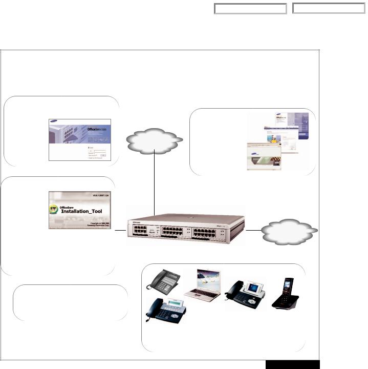
Convergence: One Solution
(Voice, Data, Wireless)
OfficeServ Management
Web Browser
Internet
Explorer 6.0
(Voice Mail
AA)
Installation Tool
Local/Remote
Programming
LAN/MODEM
Connectivity Database Upload/Download
Offline Database Viewing Search Engine (By MMC/Title) Software Upgrades to MMC+ Link to Web Management
Data Services
4 Port PoE Switch (4SWM)
Applications
OS Call
OS Operator
PSTN OS EasySet
OS Dataview
OS Open TSP
LAN
OfficeServ 7100
|
|
|
|
|
Softphone |
|
|
|
|
|
|
|
|
|
|
|
|
|
|
|
|
|
|
|
|
|
|
|
|
|
||
|
|
|
|
|
|
|
|
|
|
|
|
|
|
|
|
|
|
|
|
|
|
|
|
|
|
|
|
|
IP Phones |
|
Wireless |
|
|
|
|
|
|
|
|
|
|
Phone |
|
|
|
|
|
|
|
|
|
|||
|
TDM and |
|
|
|
|
|
|
|
||
|
|
|
|
|
|
|
|
|
||
|
|
|
|
|
|
|
|
|||
|
Analog sets |
|
|
Voice Services |
|
|
|
|||
|
|
|
|
|
|
|
|
|
|
|
FIGURE 1-1
PART 1. SYSTEM OVERVIEW
1.1 GENERAL DESCRIPTION
The OfficeServ 7100 is an “office in a box” solution that converges LAN switching functions (LAN/WAN) with the 99.999% reliability of TDM voice processing. The OfficeServ 7100 IP platform supports industry standard Voice over Internet Protocol (VoIP) as well as the more robust Telephony over IP (ToIP). The integrated Layer 2 PoE switch module adds powerful access capabilities providing data network solution for your enterprise. Combine these technologies with Samsung’s Wireless LAN IP Handsets, embedded Voice Mail Application, a suite of OfficeServ Computer Telephony applications, and much more, all in one powerful platform….A COMPLETE VOICE SOLUTION FOR THE ENTERPRISE.
1.1

Home Page |
|
Table of Contents |
|
|
|
The OfficeServ 7100 can be rack-mounted in a standard 19” data rack wall-mounted or set on a desktop. Its compact cabinet design, RJ-45 connectors, and CAT 5 cabling allows it to easily integrate into any data center environment along with existing data equipment. Expanding the OfficeServ 7100 system is both economical and easy. With a single cabinet providing 2 universal card slots, its low and high density card design allows greater flexibility when configuring a system for the right combination of lines and stations. A removable software pack MMC+ makes it convenient to upgrade to future feature packages.
The OfficeServ 7100 offers a variety of interface cards that allow connection to the public telephone network or to private networks using either analog or digital circuits. Proprietary digital phones called “keysets”connect to Digital Line Interface cards (DLM). In addition to these conventional digital keyset, Samsung offers a complete line-up of IP terminals.These IP terminals use the latest Voice over Internet Protocol (VoIP) technology and can be deployed over LANs or WANs. They are ideal for distant (remote) locations providing all the benefits of the OfficeServ 7100 to home workers and road warriors. Standard telephones generally called “single line sets” connect to single line interface cards (SLM). In addition, DLI station ports are used to connect peripheral devices such as door phones and add-on modules. Miscellaneous circuits are built-in to allow such optional features as external paging, music on hold, background music, and common audible devices.
All digital and IP telephones utilize a single PCB with surface-mounted components assuring the highest product quality and long life. Samsung’s customary large, easy-to-read displays and LEDs in the button design make them much easier to use. In many instances, sophisticated features are made simple through the use of friendly display prompts or push-on/push-off feature keys.
The OfficeServ 7100 includes all of this, PLUS the same, robust, time proven, market tested feature package offered on the OfficeServ 7200 and OfficeServ 7400 products.
BENEFITS
•End to End Samsung components, Samsung Support and Samsung Training. The Ultimate in single source Shopping and maintenance!
•The OfficeServ 7100 can also integrate into an existing office data network providing many solutions such as isolating voice traffic onto the separate data network.
•The OfficeServ 7100 networks (via SPNET over IP or Qsig over PRI) to other 7100’s or any OfficeServ 7400, 7200, 500 or 100 systems.
1.2

Home Page |
|
Table of Contents |
|
|
|
1.2 SIZE AND CONFIGURATION
The OfficeServ 7100 is a modular and flexible platform. See figures 1-2 , 1-3 and 1-4.
The Main Cabinet has one (1) dedicated processor slot for the MP10 (Main Processor) and two (2) universal slots. Each of the card slots provide 64 communication channels to support high density modules. See figure 1-3
FIGURE 1-2
Cabinet 1: 2 Universal Slots
MP10 |
U-Slot |
U-Slot |
(Slot 0) |
(Slot 1) |
(Slot 2) |
|
|
|
FIGURE 1-3
OfficeServ 7100 Capacities
When configuring a system to meet your requirements, select the appropriate number of interface cards listed in Part 2 of this book to support the various types of switches, trunks, stations, voice mail and miscellaneous functions. Combine both the physical ports of the main cabinet with the virtual ports in virtual cabinets 2 through 5 (see figure 1.6) to build a system as required. Your authorized Samsung Installation and Service Company has special knowledge and training to do this.
The following table indicates the maximum number of each circuit type or device available in the OfficeServ 7100. The system architecture is designed to be extremely flexible so as to provide a myriad of configurations. However it is impossible to accommodate all the maximum numbers into one system.
ITEM |
MAXIMUM # |
AVAILABLE HARDWARE |
||
|
|
|
||
Max # of Analog Trunk Ports |
20 |
4TRM and/or 8TRK |
||
|
|
|
|
|
Max # of Digital Trunk Ports |
23 |
TEPRIa = 23 (23B + D) |
||
PRI ONLY. (It does not support T1 trunk) |
||||
|
|
|
||
|
|
|
|
|
MAX # OF ANALOG + DIGITAL TRUNKS CANNOT EXCEED 24. |
|
|
||
|
|
|
||
Max # of MGI Ports |
24 |
8 MGI Embedded (MP10) and/or MGI-16 |
||
|
|
|
||
Max # of Analog Sets |
24 |
4SLM, 8SLI and/or 16MWSLI |
||
|
|
|
||
Max # of Digital Sets |
24 |
4DLM, 8DLI, 8COMBO and/or 16DLI |
||
|
|
|
|
|
MAX # OF STATION PORTS CANNOT EXCEED 32. |
|
|
||
|
|
|
||
Max # of VM Ports |
4 |
Embedded on the MP10 |
||
|
|
|
|
|
Max # of IP-UMS Ports |
N/A |
|
|
|
|
|
|
||
Max # of Virtual Ports Supported |
96 |
8 channels x 3 slots x 4 cabinets = 96 |
||
|
|
|
||
Max # of H.323 Trunk Ports |
24 |
3 virtual slots x 8 ports = 24 |
||
|
|
|
|
|
|
|
|
FIGURE 1-4 |
|
|
1.3 |
|
|
|
Home Page |
|
Table of Contents |
|
|
|
ITEM |
MAXIMUM # |
AVAILABLE HARDWARE |
|
|
|
|
|
Max # of SIP Trunk Ports |
24 |
3 virtual slots x 8 ports = 24 |
|
|
|
|
|
Max # of SPNet Trunk Ports |
24 |
MGI16 + 8 embedded on MP10 = 24 |
|
|
|
|
|
MAX # OF SIP + SPNET + H.323 TRUNK PORTS CANNOT EXCEED 24. |
|||
|
|
|
|
Max # of Virtual SLI Ports |
24 |
3 virtual slots x 8 ports = 24 |
|
|
|
|
|
Max # of Virtual DLI Ports |
24 |
3 virtual slots x 8 ports = 24 |
|
|
|
|
|
MAX # OF VIRTUAL ANALOG + DIGITAL STATION PORTS CANNOT EXCEED 32. |
|||
|
|
|
|
Max # of Samsung IP Phone Ports |
32 |
4 virtual slots x 8 ports = 32 |
|
|
|
|
|
Max # of WLAN Phone Ports |
24 |
3 virtual slots x 8 ports (SMT-W5100E) = 24 |
|
|
|
|
|
MAX # OF IP + SOFTPHONES + WLAN STATIONS CANNOT EXCEED 32. |
|||
|
|
|
|
Max # of Network Nodes |
99 |
Using SPNet over IP |
|
|
|
|
|
Max # of Station Group Members |
32 |
Any ring type. |
|
|
|
|
|
MAX STATION + TRUNKS + VOICEMAIL |
60 |
32 STATIONS + 24 TRUNKS + 4 VOICEMAIL = 60 |
|
|
|
|
|
|
|
|
|
|
|
|
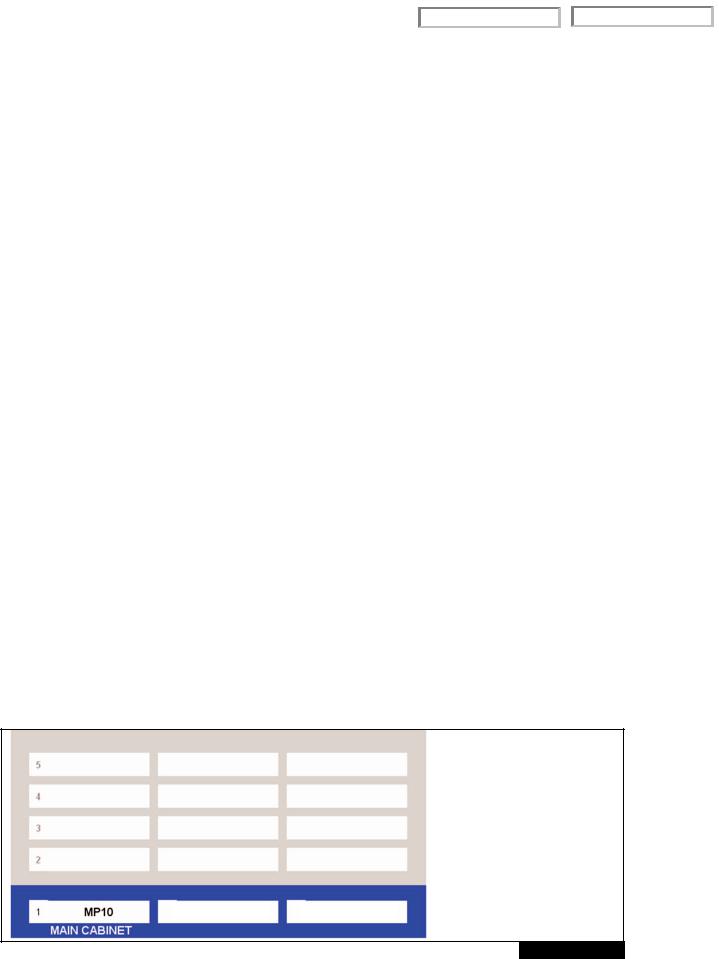
FIGURE 1-4 |
Figure 1.4 indicates the physical and virtual cabinets available in the OfficeServ 7100. Physical card slots in cabinet 1 support the various combinations of cards detailed in Part 2. HARDWARE DESCRIPTIONS. Virtual cabinets 2~5 provide three (3) slots each with each slot providing 8 ports (communication channels). The total virtual devices allowed is 96.
Virtual devices are stations and trunks that exist in the software database but do not require a physical connection to cards in the cabinet. The virtual stations or trunks are:
1.Single line telephone – SLT
2.Digital telephone – DGT
3.IP telephones – ITP
4.Wireless IP handsets – WIP
5.Samsung proprietary network trunk – SPNet
6.SIP Trunks – SIP-T
7.H.323 Trunks – H323
8.Basic Rate Interface Station – BRI-STN (Not Used in the USA)
8 Channels x 3 Slots
x 4 Cabinets = 96
VIRTUAL CABINETS
U-SLOT U-SLOT
FIGURE 1-5
1.4

Home Page |
|
Table of Contents |
|
|
|
SAMPLE CONFIGURATION
To better understand how the OfficeServ 7100 is configured, below is an example of a practical 4 x 12 configuration using a combination of digital and ITP telephones. Cabinet 1 shows the type of card installed in each physical slot. Cabinets 2~5 show the default to the virtual assignments for each virtual slot. The IP telephones may be connected to existing (external) data equipment or OfficeServ 7100 data module (4SWM) in a separate stand alone cabinet.
Cabinet 1: Sample 4 x 12 Default Slot Configuration
12 Stations and 4 Trunks
•4 Analog Loop Trunks
•8 Digital Telephones
•4 IP Telephones
•4 MGI Channels (VoIP)
•4 Voice Mail Ports
(MGI-4) (VM-4)
FIGURE 1-6
VIRTUAL CABINET SLOT ASSIGNMENT
FIGURE 1-7
1.5

Home Page |
|
Table of Contents |
|
|
|
1.3 TECHNOLOGY
MEMORY
The system operates using stored program control. This program is stored on a 256MB Multimedia Plus (MMC+) card inserted into the Main Processor card (MP10). The MMC+ card also provides space for a backup customer database and voicemail storage. The customer database is stored indefinitely in NAND Flash. 2MB of SRAM backed up by a super capacitor stores information such as Call Logs, Alarms, UCD call statistics, program logs and traffic reports up to 24 hours without main system power.
MICROPROCESSORS
OfficeServ 7100 uses distributed processing. Its primary processor is a M82511G (MP10), operating at a clock speed of 375 MHz.This provides all the main processing necessary for the system. The tertiary level of processing is done in the keysets. The digital keysets use a Hitachi H8 processor for data communication within the system.
1.4 PROGRAMMING
The OfficeServ 7100 is a self-configuring system. This means that immediately after applying power, the OfficeServ 7100 reads the types and locations of all installed interface cards and keysets and assigns default data to them. This data provides for system operation within a few minutes after applying power. All trunks and stations are assigned three digit numbers according to the default numbering plan. This numbering plan is flexible and may be changed to suit customer requirements. The installing technician customizes this default data to meet the end user’s requirements.The system comes up default in a 4 CO line by 8 station squared configuration, with Caller ID enabled and 4 ports of voicemail/auto attendant.
The OfficeServ 7100 also provides a proprietary application called Installation Tool (IS Tool). This application can be loaded onto any high performance PC (that meets the minimum requirements) and it is used only to program the telephone system from anywhere in the world, provided there is a LAN/WAN or modem connection.
This permits technicians to program the phone system, modify the customer database or download (save) the entire customer database to a file. This file can be saved as a back up and can be uploaded when required to restore the database. The IS Tool can also be used to view the customer database offline, and to send new loads of software upgrades to the MMC+ of a live system.
The system can be programmed from any IP or digital two line display keyset without interrupting system operation.There are three levels of programming: technician ,customer and station.The technician level has access to all programs and can allow the customer access to system programs as needed. Technician and customer access levels are controlled by a different security pass codes and access procedure.
The OfficeServ 7100 provides a proprietary Web based program called Web Management for programming embedded voicemail/AA. It allows programming from any where in the world provided there is a LAN/WAN connection to the MP10. The Web Management program runs on a Web Server and uses Internet Explorer V6.0 as its interface. This permits a technician to program the voicemail/AA using a personal computer. Use Web Management on-site to modify the customer database (VM/AA only) or to download (save) the entire customer database (VM/AA only).Through the use of LAN or WAN connection, an PC can access the OfficeServ 7100 system remotely (off-site) to make database changes or perform uploads or downloads of the customer database as if the technician were on-site.
1.5 MIGRATION TO OfficeServ 7200 or OfficeServ 7400
For businesses using the OfficeServ 7100, Samsung provides a convenient, easy and affordable migration path to the larger OfficeServ 7200 or OfficeServ 7400 systems. Most of the keysets can become part of a much larger OfficeServ 7000 system. Features and operation are the same so there is no need to retrain users. See the OfficeServ 7200 or OfficeServ 7400 General Description for more details.
1.6
Home Page |
|
Table of Contents |
|
|
|
PART 2. HARDWARE DESCRIPTIONS
2.1 SYSTEM CABINET
The OfficeServ 7100 cabinet has three slots to mount boards, an AC to DC power supply, cooling fan, a battery backup connector and power on/off switch. The cabinet is designed to be rack mounted in a 19 inch rack, wallmounted with a wall-mounted bracket or placed on a table top. Slot 0 is exclusively used for the MP10 processor card, and slots 1 and 2 are 64 channel universal slots that the UNI cards or other OfficeServ 7200/OfficeServ 7400 station/trunk cards can be installed in.
2.2 PROCESSOR CARDS
MP10 (MAIN PROCESSOR CARD)
This is the main processor controlling system operation. The MP10 always goes in slot 0 of the main cabinet. The MP10 provides a LAN connection, a MISC port (external page, MOH/BGM, loud/common bell), an SIO port (Samsung Maintenance Only),four universal ports for either digital phones or power of Ethernet ports (dependant on the type of daughterboard module plugged in), a internal modem slot, and a multimedia card (MMC+) slot which can accommodate a 256MB card containing the system software.The MP10 also includes embedded Automated Attendant,Voicemail, and MGI channels (license key required). The MP10 card cannot migrate to the OfficeServ 7200 or OfficeServ 7400 systems.
The MP10 have a connector for mounting either a 4DLM card or a 4SWM card. When the 4DLM card is installed on the processor it will provide an interface for 4 Digital telephone sets. When the 4SWM card is installed on the processor it will provide an interface for 4 power over ethernet (POE) ports. The MP10 also has a connector for mounting the optional modem board. This modem board can be used for remote access to system administration at installation that do not have a LAN or WAN connection. This is the same modem card used in the other OfficeServ systems. If the 4SWM is installed the switch and LAN is automatically connected by way of the backplane. In addition it may be used as a backup for LAN connectivity.
2.2.1 EMBEDDED APPLICATIONS
VOICEMAIL/AUTO ATTENDANT
The MP10 processor has the voicemail and automated attendant application embedded onto the card.The VMAA is designed to meet the demands of the sophisticated voice mail user without sacrificing simplicity. The Automated Attendant is available with four ports for processing voicemail/AA traffic routed to the Automated Attendant.The same four ports can be enabled to perform both the voicemail and automated attendant function of answering calls and storing messages into mailboxes for each extension.
MEDIA GATEWAY INTERFACE
Eight (8) MGI channels are embedded on the MP10 processor, and can be enabled (licensed in 1 port increments) to support VoIP functions such as IP phones, IP networking, and IP trunking. The embedded MGI channels can be enabled to support the following capabilities:
•IP Phones
•IP Networking (Network multiple systems over an SPNet IP Network)*
•G.729 CODEC, G.723.1, G.711, G.729A CODECs
•IP Trunking (SIP/H.323)
•T.38 Fax CODEC
•Inband or Out-of-band signaling of DTMF tones
*The OfficeServ 7100 can network using QSig over PRI or SP-Net over IP to other Samsung OfficeServ systems.
2.1

Home Page |
|
Table of Contents |
|
|
|
Note: An additional 16 MGI channels can be added to the system if necessary by installing an MGI16 card.
The MP10 also provides various common resources (standard equipment) that are shared through the system. The MP10 provides the following: background music/music on hold audio inputs (radios, digital announcers, etc.), external paging audio output, loud bell audio output, common bell and programmable dry contact closures. Other common resources embedded on the MP10 are as follows:
•Two contact relays
•Six 5 party conference circuits
•Eight Caller ID sender/receivers
•Eight DTMF receiver/transmitters
•Eight MGI channels (Licensed IP phones, IP trunks and IP networking)
•Four Voice Mail/Auto Attendant ports
2.2.2 MULTIMEDIA PLUS
An OfficeServ 7100 system must have a Multimedia Plus (MMC+) card installed in the main control processor (MP10) as the MMC+ card contains the system operating software. The MMC+ card can also be used to store a backup customer database and voicemail messages to supplement the database stored in the NAND Flash.
2.3 INTERFACE CARDS
UNI CARD
These cards provide the interface connections for telephone lines and stations to the KSU.These cards fit into the universal card slots to configure the system as required.
The UNI card can be installed in any of the two universal slots of the OfficeServ 7100 system.The UNI card is used to accommodate other optional daughter boards. Any combination of the 4DLM, 4SLM or 4TRM modules can be installed in any of the three slots on the UNI card for a total of 12 ports per UNI card. This type of slot configuration allows the customers to grow or expand in 4 port increments. Customer can start out and configure the system as a 4 line by 8 station system and later expand to a 8 by 16 configuration and beyond.
Each slot can be used as a voice trunk line board or voice station board depending on the mounted option board. If a 4TRM option board is mounted in the UNI board, it operates as a voice trunk line board. If 4SLM and 4DLM option boards are mounted, it operates as a voice station board. The UNI card is not hot swappable. This card can not migrate to the OfficeServ 7200 or OfficeServ 7400 systems. See installation manual for details.
2.4 DAUGHTERBOARD CARDS
4DLM
This daughter board module is a four circuit digital station interface card that provides 1B+D service for the different models of Samsung digital keyset. The 4DLM can be inserted in any of the three slots on the UNI card or on the MP10 card. See installation manual for details.
4SLM
This daughter board module is a four circuit analog station interface for industry standard single line telephones that require operation of an industry standard message waiting lamp with a voltage range of 85~96 VDC.The card can only be installed on the UNI card. The lamp can flash at a rate of 200ms to 500ms ON/OFF times. The 4SLM does not contain any over-voltage protection and is not qualified a OPX. It also does not contain DTMF receivers,
2.2
Home Page |
|
Table of Contents |
|
|
|
but instead shares the system DSP resources. The OfficeServ 7100 4SLM supports Caller ID to single line telephones. The 4SLM can only be inserted in any of the three slots on the UNI card. Each port on this card is intended for connection to one telephone. Connecting multiple telephones to a port may result in incorrect operation or damage to the card. See installation manual for details.
4TRM
This card contains four loop start C.O. lines interface circuits with C.O. disconnect detection. It also contains the circuitry needed for Caller ID.
The 4TRM can only be inserted in any of the three slots on the UNI card. Each port on this card is intended for connection to Telco. See installation manual for details.
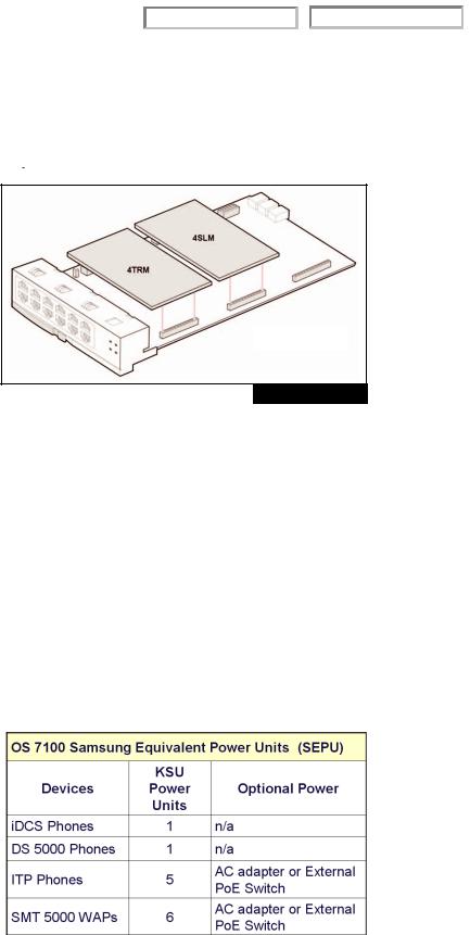
4SWM (DATA MODULE)
UNI CARD
FIGURE 2-1
The OfficeServ 7100 supports one enterprise class data module. The 4SWM can be combined in the same cabinets with the telephone system cards to provide a converged voice and data solution. 4SWM, which is a data board of OfficeServ 7100, provides 10/100 BASE-T interface and performs the Layer2 Switch function as the data transmission/reception board to/from a LAN. When installed, the 4SWM module provides connection for four (4) PoE ports off the front panel of the MP10 card.These ports can be used to connect ITP phones,WAPs, SP-Net, LAN printers, PC programming, uplink to other data switches or any other Ethernet devices. This module may be used in conjunction with the licensed MGI channels when providing IP telephony services. This module can only be installed on the optional daughter board slot on the MP10 card. See installation manual for details.
The main functions of the 4SWM board are as follows:
•Auto-detection function of 10/100 BASE-T and Full/Half duplex
•802.1p and VLAN function to support QoS
•Layer 2 Switch function
Power constraints must be taken into consideration when plugging ITP phones and WAP devices into the 4SWM PoE module.
•The OfficeServ 7100 power supply supports a maximum of 24 TDM phones or SEPU (Samsung equivalent power units). One power unit is equal to one (2 line TDM phone).
•A maximum of 4 ITP phones or 4 WAPs can be supported by the 4SWM PoE Module.
•Each time an ITP phone is plugged into the 4SWM PoE port, the system capacity for TDM phones is decreased by 5.
•Each time a WAP is plugged into the 4SWM PoE port, the system capacity for TDM
phones is decreased by 6. |
FIGURE 2-2 |
•External power can be used to power the ITP phones and WAPs. If external power is used to supply power to the ITP phones or WAPs, no SEPU are used from the OS 7100 4SWM PoE module.
2.3

Home Page |
|
Table of Contents |
|
|
|
2.5 OfficeServ 7200/OfficeServ 7400 TRUNK CARDS
8TRK BOARD
This card contains eight loop start C.O. line interface circuits with C.O. disconnect detection. It also contains the circuitry needed for Caller ID. It can be inserted in any universal card slot in all cabinets. The 8TRK card is not hot swappable.
TEPRI/TEPRIa DIGITAL TRUNK BOARD
The card can be programmed as a PRI and will provide 23 bearer channels and 1 data channel (23B+D). This card can be installed in any universal slot in any OfficeServ 7100 cabinet.This card is also used for networking to other systems (QSig/PRI networking)*. Add as many as required.T1 is not supported on this card in the OfficeServ 7100. The TEPRI/TEPRIa is not hot swappable.
2.6 OfficeServ 7200/OfficeServ 7400 VoIP CARDS
MGI-16 (MEDIA GATEWAY INTERFACE)
The MGI-16 card supports 16 VoIP channels. The MGI-16 supports the following capabilities:
•IP Phones
•IP Networking (Network multiple systems over an IP Network)*
•G.729 (8K) CODEC, G.723.1, G.711, G.729A CODECs
•IP Trunking (SIP/H.323)
•T.38 Fax CODEC
•Inband or Out-of-band signaling of DTMF tones
•801.1p, 802.1q (VLAN), QoS
2.7 OfficeServ 7200/OfficeServ 7400 STATION CARDS
8DLI
This card is an eight circuit digital station interface card that provides 1B+D service when installed in any universal card slot in all cabinets.The KDB-D/S keyset daughter boards will not work when connected to this card in the Officeserv 7100. The 8DLI card is not hot swappable.
16DLI2
This card is a sixteen circuit digital station interface card that provides 1B+D service when installed in any universal card slot in all cabinets.The KDB-D/S keyset daughter boards will not work when connected to this card in the OfficeServ 7100. The 16DLI2 card is not hot swappable
8SLI
This card is a eight circuit analog station interface for industry standard single line telephones or other analog peripheral devices.The 8SLI does not contain any over-voltage protection and is not qualified as OPX. It also does not contain DTMF receivers, but shares system DSP resources. It can be inserted in any universal card slot in all cabinets. Each port on this card is intended for connection to one telephone. Connecting multiple telephones to a port may result in incorrect operation or damage to the card.This card supports Power Fail Transfer feature. See the installation manual for details. The OfficeServ 7100 supports Caller ID to single line telephones.The 8SLI is not hot swappable.
2.4
Home Page |
|
Table of Contents |
|
|
|
16MWSLI
This card is a sixteen circuit analog station interface for industry standard single line telephones that require operation of an industry standard message waiting lamp with a voltage range of 85 ~ 96 VDC. The lamp can be programmed to be on continuously or flash at a programmable rate of 100ms to 2000ms ON/OFF times. The 16MWSLI does not contain any over-voltage protection and is not qualified as OPX. It also does not contain DTMF receivers, but instead shares the system DSP resources. It can be inserted in any universal card slot in all cabinets. Each port on this card is intended for connection to one telephone. Connecting multiple telephones to a port may result in incorrect operation or damage to the card. This card supports the Power Fail Transfer feature. See installation manual for details. The OfficeServ 7100 supports Caller ID to single line telephones. The 16MWSLI is not hot swappable.
8COMBO
This card has a combination of eight dedicated digital stations ports (1B+D) for Samsung Digital Keysets and eight dedicated analog station ports for industry standard single line telephones or other analog devices. This card installs in any universal slot in any cabinet. The OfficeServ 7100 supports Caller ID to single line telephones. The 8COMBO is not hot swappable.
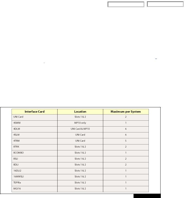
HARDWARE CAPACITIES
FIGURE 2-3
2.5
Home Page |
|
Table of Contents |
|
|
|
2.8 STATION EQUIPMENT
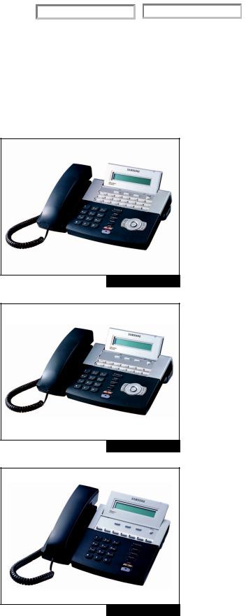
2.8.1 DS 5000 SERIES EQUIPMENT
DS 5021D KEYSET (See Figure 2–4)
•32 character display (2 x 16) with three associated soft keys and a scroll key
•21 programmable keys with tri-colored lights
•Five fixed function keys
•Terminal Status Indicator
•Built-in speakerphone
•Optional Full Duplex speakerphone module
•Eight selectable ring tones
•UP/DOWN buttons for digital control of speaker, handset and ringer volumes
•Deskor wall-mounted
FIGURE 2-4
DS 5014D KEYSET (See Figure 2–5)
•32 character display (2 x 16) with three associated soft keys and a scroll key
•14 programmable keys with tri-colored lights
•Five fixed function keys
•Terminal Status Indicator
•Built-in speakerphone
•Optional Full Duplex speakerphone module
•Eight selectable ring tones
•UP/DOWN buttons for digital control of speaker, handset and ringer volumes
•Deskor wall-mounted
FIGURE 2-5
DS 5007S KEYSET (see Figure 2–6)
•32 character display (2 x 16) with three associated soft keys and a scroll key
•7 programmable keys with tri-colored lights
•Five fixed function keys
•Terminal Status Indicator
•Built-in speakerphone
•Eight selectable ring tones
•UP/DOWN buttons for digital control of speaker, handset and ringer volumes
•Deskor wall-mounted
FIGURE 2-6
Note: The KDB-D and KDB-S Keyset daughter boards cannot be used with any keysets on the OfficeServ 7100. Only the KDB-F (full duplex) daughter boards can be used on the OfficeServ 7100.
2.6
Home Page |
|
Table of Contents |
|
|
|
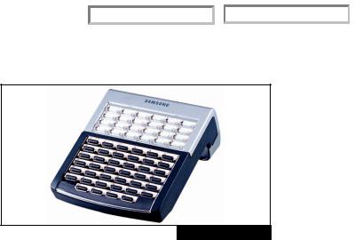
DS 5064B AOM (See Figure 2–7)
•64 programmable keys with red lights
•A maximum of 2 can be assigned to any keyset to provide additional programmable keys
•A maximum of 4 per system
Note: This AOM can be used with an IP keyset. The cosmetic design matches both the DS-5000 and ITP5100 keysets. A DLI port is required for this AOM.
FIGURE 2-7
DS 5021D KDB-F (FULL DUPLEX)
This is a daughter board that can be installed only in the DS 5021D and DS 5014D keysets. The standard speakerphone mode of operation for a DS keyset is half duplex. This means that you cannot transmit and receive speech at the same time. Adding a KDB-F to your keyset will convert the speakerphone into a full duplex mode enhancing its operation. The KDB-F does not require a second “B” channel. In addition, the KDB-F may have up to three
(3) external microphones attached to it for conference room type applications. The microphones require an “EXTMIC” key programmed on the keyset to activate or deactivate them.
Note: Only one KDB-F can be installed on a DS 5021D or DS 5014D keyset.The KDB-D/S modules are not supported on the iDCS and DS keysets on the OfficeServ 7100 system.
2.7
Home Page |
|
Table of Contents |
|
|
|
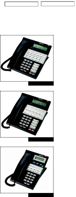
2.8.2 iDCS SERIES EQUIPMENT
iDCS 28D KEYSET (See Figure 2–8)
•32 character display (2 x 16) with three associated soft keys and a scroll key
•28 programmable keys with tri-colored lights
•Four fixed function keys
•Terminal Status Indicator
•Built-in speakerphone
•Optional full duplex speakerphone module
•Eight selectable ring tones
•UP/DOWN buttons for digital control of speaker, handset and ringer volumes
•Deskor wall-mounted
•Available in dark gray
iDCS 18D KEYSET (See Figure 2–9)
•32 character display (2 x 16) with three associated soft keys and a scroll key
•18 programmable keys with tri-colored lights
•Four fixed function keys
•Terminal Status Indicator
•Built-in speakerphone
•Optional full duplex speakerphone module
•Eight selectable ring tones
•UP/DOWN buttons for digital control of speaker, handset and ringer volumes
•Deskor wall-mounted
•Available in dark gray
iDCS 8D KEYSET (see Figure 2–10)
•32 character display (2 x 16) with three associated soft keys and a scroll key
•8 programmable keys with tri-colored lights
•Four fixed function keys
•Terminal Status Indicator
•Built-in speakerphone
•Eight selectable ring tones
•UP/DOWN buttons for digital control of speaker, handset and ringer volumes
•Deskor wall-mounted
•Available in dark gray
FIGURE 2-8
FIGURE 2-9
FIGURE 2-10
Note: The iDCS keyset type cannot use the KDB-D/S keyset daughter boards on the OfficeServ 7100 system. The iDCS 8D keyset cannot use the 14 button strip.
2.8
Home Page |
|
Table of Contents |
|
|
|
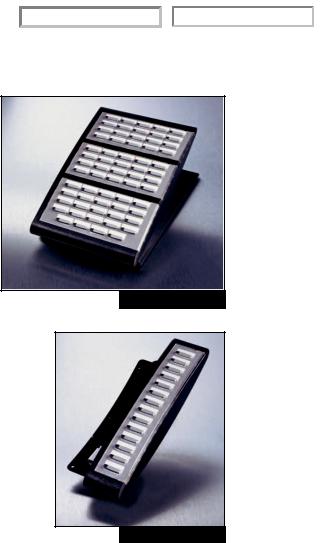
iDCS 64B AOM (See Figure 2–11)
•64 programmable keys with red lights
•A maximum of 2 can be assigned to any keyset to provide additional programmable keys
•A maximum of 4 per system
•Available in dark gray
FIGURE 2-11
iDCS 14B STRIP (See Figure 2–12)
•14 programmable keys with red lights
•A maximum of one can be added to any 28D or 18D keyset to provide additional programmable keys
•Available in dark gray
FIGURE 2-12
iDCS KDB-FULL DUPLEX (FKDBF)
This is a daughter board that can be installed only in the 18 or 28 button keysets. The standard speakerphone mode of operation for an iDCS keyset is “half duplex”.This means that you cannot transmit and receive speech at the same time. Adding an FKDBF to your keyset will convert the speakerphone into full duplex mode enhancing its operation. The FKDBF does not require a second “B” channel like the FKDBD or FKDBS and so can be used on any DLI card. In addition the FKDBF may have up to three (3) external microphones attached to it for conference room type applications. These microphones require an “EXTMIC” key programmed on the keyset to activate or deactivate them.
Note: Only one KDBF can be installed on a keyset. The KDB-D/KDB-S modules are not supported on the iDCS and DS keysets on the OfficeServ 7100 system.
2.9
Home Page |
|
Table of Contents |
|
|
|
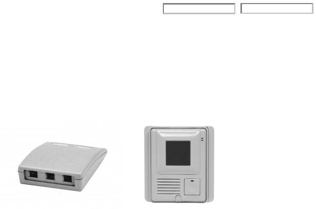
DOOR PHONE INTERFACE MODULE (DPIM) & DOOR PHONE
(see Figures 2–13 and 2–14)
•The DPIM adapts any DLI circuit for use with the door phone unit
•Commonly used to request entry through locked doors (interior or exterior) or as a room monitoring box
•Provides contact control to be used with customer-provided electric door lock
•Door phone is wall-mounted
•Door phone is weather resistant
|
|
|
|
|
|
FIGURE 2-13 |
|
|
FIGURE 2-14 |
2.10
Home Page |
|
Table of Contents |
|
|
|
2.8.3 OfficeServ™ ITP-5100 SERIES EQUIPMENT
ITP-5121D IP KEYSET (See Figure 2–15)
•32 character display (2 x 16) with three associated soft keys and a scroll key
•Built-in Full Duplex speakerphone
•21 programmable keys with tri-colored LEDs
•Five fixed function keys
•UP/DOWN buttons for digital control of speaker, handset and ringer volumes
•Eight selectable ring tones
•Desk or wall-mounted
•2 Port Switch
• Supports PoE (Power over Ethernet) |
FIGURE 2-15 |
ITP-5112L IP KEYSET (See Figure 2–16)
•99 programmable keys (soft keys)
•Built-in Full Duplex speakerphone
•Five fixed function keys
•Large color TFT display with twelve associated soft keys and a scroll wheel
•UP/DOWN buttons for digital control of speaker, handset and ringer volumes
•Multiple user-selectable ring tones
•Navigation key
•Built-in applications: Phone Book, E-Diary, Calendar, and Calculator.
•User-selectable menu styles and backgrounds.
•2 Port Switch
•Supports PoE (Power over Ethernet)
ITP-5107S IP KEYSET (See Figure 2–17)
•32 character display (2 x 16) with three associated soft keys and a scroll key
•Built-in Full Duplex speakerphone
•7 programmable keys with tri-colored LEDs
•Five fixed function keys
•UP/DOWN buttons for digital control of speaker, handset and ringer volumes
•Eight selectable ring tones
•Desk or wall-mounted
•Supports PoE (Power over Ethernet)
DS 5064B AOM (See Figure 2–18)
•64 programmable keys with red lights
•A maximum of 2 can be assigned to any keyset to provide additional programmable keys
•A maximum of 4 per system
Note: This AOM can be used with an IP keyset. The
cosmetic design matches both the DS-5000 and ITP-5100 keysets.
FIGURE 2-16
FIGURE 2-17
FIGURE 2-18
2.11
Home Page |
|
Table of Contents |
|
|
|
2.8.4 OfficeServ™ SOFTPHONE
Samsung OfficeServ™ Softphone is a software-based application that turns your computer into a full-featured Samsung IP telephone. It is installed directly onto your laptop or desktop PC running Microsoft Windows XP or 2000 operating system. Once a USB headset or a USB handset is connected; the Softphone delivers virtually identical functionality as the ITP-5112 L and ITP-5121D desktop ITP phones.
OfficeServ™ Softphone is ideal for telecommuter and mobile users. Remote workers can simply connect their laptop to the corporate network, snap in a USB headset, and function as if they were in their own office. They can place, receive, and handle calls on both the internal and external network, providing a truly portable and practical solution.
2.8.5 OfficeServ™ Wireless
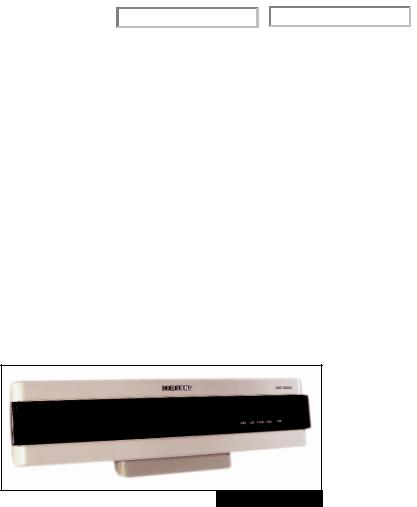
WIRELESS LAN ACCESS POINT (SMT-R2000) (See Figure 2–19)
The wireless access point (SMT-R2000) provides wireless coverage throughout a building and surrounding areas. It supports IEEE 802.11a/b/g WLAN standard for both voice and data. It gives priority to voice packets. The quality of the service for voice is always guaranteed.
FIGURE 2-19
Highlights of SMT-R2000 Features
•Two radios. Radio 1: 5GHz IEEE 802.11a (54 Mbps) and Radio 2: 2.4 GHz IEEE 802.11b/g (54 Mbps)
•8 voice calls per Access Point.
•Wireless data stations or handsets association per AP, 802.11a: 255, 802.11b/g: 255. Total: 32
•Wireless Access Point or repeater mode
•RP-SMA type connector for external antenna
•Router mode support
•Enhanced security (WEP, WPA, WPA2, etc.)
•QoS supports 802.1 p/q, DSCP, 802.11e (WMM), ToS
•PoE (Power over Ethernet) support or External Power Adapter (supplied)
•Easy Web Management
•Wi-Fi certified
•No MGI channel required for conversation between handset to handset or handset to ITP desktop phone
2.12
Home Page |
|
Table of Contents |
|
|
|
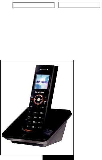
WIRELESS INTERNET PHONE (SMT-W5100E HANDSETS) (see Figure 2-20)
Wireless handset (SMT-W5100E) is a compact hand-held unit that works within the Samsung OfficeServ Wireless system.The three ounce handset comes with a rich set of features. Its graphical display and menu-driven function make it very simple to use. The handset package comes with a charger, two batteries, a leather carrying case and a headset with hook switch.
Highlights of SMT-W5100E Features
•IEEE 802.11g
•Wi-Fi certified
•1.5: color LCD
•Security: WEP/WPA/WPA2
•QoS: 802.11e (WMM)
•Caller name and number display
•Call Waiting
•Voice mail indication
•Hot key for voice mail access
•System hold
•Call transfer
•Call forward
•Call mute
•Call pick up
•Do not disturb
•Dynamic soft keys
•Hard keys for TRANSFER, HOLD, and CONFERENCE
•Redial
• Pre-dial |
FIGURE 2-20 |
•Local phone book with 2,400 entries.
—Each entry can store 3 phone numbers
—There is a total of 800 phone numbers
•Hot key for vibrator function (*)
•99 incoming call log, 99 outgoing call log, and 99 missed call log
•Adjustable volume
•16 different ringer tones and adjustable ringer volume
•Hot key for keypad lock/un-lock (#)
•4 hours talk time
•40 hours standby time
•3.5 hours fast charger
•Spare battery slot in charger
•Software upgrade through wireless connection
2.13

Home Page |
|
Table of Contents |
|
|
|
PART 3. SPECIFICATIONS
3.1 ELECTRICAL SPECIFICATIONS
POWER SUPPLY UNIT
The Power Supply Unit (PSU) is installed in the cabinet of the OfficeServ 7100. The PSU supplies the power of -48 V DC received from the external battery backup power supply unit to each board. The rating is as follows.
• INPUT RATING: 100-120 VAC; 2A; 50/60 Hz or DC -48 V, 3A
The specifications of the power I/O are shown in the table below.
3.1a I/O VOLTAGE of the PSU
|
Input Voltage |
100-120 VAC ~ 2A 50/60 Hz |
|
DC -48V ~ 3A (Battery Backup) |
|
|
|
|
|
|
|
|
|
DC -54V, 1.1A |
|
|
|
|
|
DC +5V, 5.0A |
|
|
|
PSU (OfficeServ 7100) |
Output Voltage |
DC -5.3V, 0.3A |
|
||
|
DC +3.3V, 5A |
|
|
|
|
|
|
|
|
|
DC +12V, 0.4A |
|
|
|
|
|
DC -54.0V, 0.25A (Battery Backup) |
|
|
|
|
Maximum Power Consumption/PSU |
105 W |
|
|
|
3.2 DIMENSIONS
|
HEIGHT |
WIDTH |
DEPTH |
|
|
|
|
OfficeServ 7100 Main Cabinet |
3.11” |
17.32” |
16” |
|
|
|
|
Note: When the cabinets are rack mounted, the rack mount bracket will add some height to the system.
3.1

Home Page |
|
Table of Contents |
|
|
|
3.3 ENVIRONMENTAL LIMITS
OPERATING TEMPERATURE |
32—113 °F / 0—45 °C |
|
|
STORAGE TEMPERATURE |
14—122 °F / --10—50 °C |
|
|
HUMIDITY |
10%—90% Non-Condensing |
|
|
3.4 CABLE REQUIREMENTS
EQUIPMENT |
CABLE |
AWG |
MAX FEET |
MAX METERS |
|
|
|
|
|
DIGITAL KEYSET |
1 PR. TWISTED |
24 |
1300 |
400 |
|
|
|
|
|
ADD-ON MODULE |
1 PR. TWISTED |
24 |
1300 |
400 |
|
|
|
|
|
SINGLE LINE STATION |
1 PR. TWISTED |
24 |
3000 |
1 KM |
|
|
|
|
|
DOOR PHONE |
2 PR. TWISTED |
24 |
330* |
100 |
|
|
|
|
|
*This the maximum distance a door phone can be from the DPIM.The DPIM can be up to 900 cable feet from the KSU. The total distance must not exceed 1230 feet.
3.5 RINGS AND TONES
3.5.1 RING CYCLES
The OfficeServ 7100 provides the trunk line rings, station rings, door rings, and alarm rings. The ON/OFF cycle of each ring is shown in the table below (it is different according to the country, and can be modified by MMC programming).
3.5.1a SYSTEM RING CYCLES |
|
|
|
RING |
ON/OFF CYCLE |
|
|
TRUNK LINE RING |
1000/2000 ms |
|
|
STATION RING |
400/200/400/3000 ms |
|
|
DOOR RING |
400/200/400/200/400/2000 ms |
|
|
ALARM RING |
400/200/400/200/400/200/400/1000 ms |
|
|
Note: The ON/OFF cycle can be adjusted by changing the values of the system database.
3.2

Home Page |
|
Table of Contents |
|
|
|
3.5.2 RING
The output voltage and frequency of the ring signals in the OfficeServ 7100 are as follows:
•Output voltage: 75 Vrms Square Wave (4SLM)
•Frequency: 20 or 25 Hz
The OfficeServ 7100 provides the users with various tones to notify the users of the status of functional operations. The ON/OFF cycles of currently specified tones are shown in the table below.
3.5.3 SYSTEM TONES
TONE |
ON/OFF CYCLE |
DIAL TONE |
1000/250 ms |
BUSY TONE |
500/500 ms |
DO NOT DISTURB TONE |
250/250 ms |
RING BACK TONE |
1000/2000 ms |
CALL PARK TONE |
CONTINUOUS |
CONFIRMATION/CAUTION/BARGE-IN TONE |
50/50 ms |
CALL BACK/HOLD TONE |
500/3500 ms |
RING BACK TONE |
1000/2000 ms |
ERROR/NUMBER UNOBTAINABLE TONE |
250/250 ms |
MESSAGE CAMP ON TONE |
CONTINUOUS |
Note: The ON/OFF cycle can be adjusted by changing the values of the system database.
3.6 KEYSET LED INDICATIONS
CONDITION |
LED COLOR |
LED ON |
LED OFF |
LINE IDLE |
OFF |
— |
OFF |
LINE IN USE |
RED / GREEN |
STEADY |
— |
RECALL |
AMBER |
500 ms |
500 ms |
CALL ON HOLD |
RED / GREEN |
500 ms |
500 ms |
RINGING C.O. CALL |
GREEN |
100 ms |
100 ms |
RINGING INTERNAL CALL |
GREEN |
100 ms |
100 ms |
DND INDICATION |
RED |
112 IPM for 500 ms |
500 ms |
OPERATOR CALLS |
RED |
100 ms |
100 ms |
ANS / RLS (DND)* |
RED |
112 IPM for 500 ms |
500 ms |
ANS / RLS (HANDSET MODE)** |
RED |
STEADY |
— |
*Overrides headset mode.
3.3

Home Page |
|
Table of Contents |
|
|
|
OfficeServ 7100 Feature Maximum Capacities
Station Groups |
20 |
|
|
|
|
Station Group Members |
32 |
|
(Sequential or Distributed) |
||
|
||
|
|
|
Trunk Groups |
11 |
|
|
|
|
UCD Groups |
10 |
|
|
|
|
Unconditional Group Members |
32 |
|
|
|
|
Trunk Group Members |
60 |
|
|
|
|
Internal Page Members |
32 x 5 |
|
|
|
|
External Page Members |
4 x 2 |
|
|
|
|
Toll Restriction Entries |
500 |
|
|
|
|
Toll Allowance Entries |
500 |
|
|
|
|
DID Translation Entries |
999 |
|
|
|
|
Authorization Code Entries |
500 |
|
|
|
|
Account Code Entries |
999 |
|
|
|
|
LCR Digit Entries |
2000 |
|
|
|
|
LCR Modify Digit Tables |
200 |
|
|
|
|
LCR Time Tables |
4 |
|
|
|
|
LCR Time Bands |
4 |
|
|
|
|
LCR Route Tables |
99 |
|
|
|
|
Alarm Reminder Buffers |
3 |
|
|
|
|
Speed Dial Entries |
2000 |
|
|
|
|
System Buffers (MAX) |
500 / 950 |
|
|
|
|
Station Buffers (MAX) |
50 |
|
|
|
|
CID Review Buffers |
2000 |
|
|
|
|
CID Abandon Lists |
100 |
|
|
|
|
CID Name Translation Entries |
1000 |
|
|
|
|
Call Buttons per Station |
8 |
|
|
|
Call Logs Entries |
2000 |
|
|
|
|
Call Log per Station |
50 |
|
|
|
|
Tenant Groups |
1 |
|
|
|
|
Ring Plans |
6 |
|
|
|
|
Programmed Messages |
15 (10+5) |
|
|
|
|
14B AOM per Station |
1 |
|
|
|
|
64B AOM per Station |
2 |
|
|
|
|
Call Cost Digit Entries |
500 |
|
|
|
|
Call Cost Rate Tables |
8 |
|
|
|
|
PBX Access Code Entries |
5 |
|
|
|
|
Special Code Entries |
10 |
|
|
|
|
Emergency/Override Code |
8 |
|
Entries |
||
|
||
|
|
|
Holiday Entries |
60 |
|
|
|
|
Class of Service |
30 |
|
|
|
|
LCR Classes |
8 |
|
|
|
|
Message Waiting per Station |
5 |
|
|
|
|
Conference Groups |
6 |
|
|
|
|
Conference Group Members |
4 |
|
(Add-On) |
||
|
||
|
|
|
Pickup Groups |
20 |
|
|
|
|
Internal/External Page Zones |
5/2 |
|
|
|
|
Redial & External FWD Dial Digits |
18 |
|
|
|
|
IP Keysets |
32 |
|
|
|
|
Virtual Extensions |
96 |
|
|
|
|
Text Messages |
10/100 |
|
|
|
|
Agent Pin Numbers |
100 |
|
|
|
3.4

Home Page |
|
Table of Contents |
|
|
|
PART 4. BUSINESS FEATURE PACKAGE
SYSTEM FEATURES
Account Code Entry |
Caller ID Features |
OfficeServ™ Call |
Forced - Verified |
Name/Number Display |
OfficeServ™ Operator |
Forced - Not Verified |
Next Call |
OfficeServ™ Softphone |
Voluntary |
Save Caller ID Number |
Conference Group |
Account Code Key |
Store Caller ID Number |
Customer Set Relocation |
Account Code Key - One Touch |
Inquire Park/Hold |
Data Security |
Administrator Program Key |
Caller ID Review List |
Database Printout |
All Call Voice Page |
Investigate |
Daylight Saving Time-Automatic |
Attention Tone |
Abandon Call List |
Dialed Number Identification Service (DNIS) |
Audio Message with Alarm |
Caller ID on SMDR |
Direct In Lines |
(Timer) Reminder |
Number to Name Translation |
Direct Inward Dialing (DID) T1 |
Authorization Codes |
Caller ID to PSTN |
Day/Night Routing |
Forced |
Caller ID to Analog Port |
Busy or Camp-On Option |
Voluntary |
Call Forwarding |
MOH Source |
Auto Answer on CO |
All Calls |
DID Call Limits |
Auto Attendant† |
Busy |
Direct Inward System Access (DISA) |
Automatic Call Distribution (ACD) |
No Answer |
Direct Trunk Selection |
Automatic Hold |
Busy/No Answer |
Directory Names |
Background Music |
Forward DND |
DISA Security |
Branch Group |
Follow Me |
Distinctive Ringing |
Call Activity Display |
External |
Door Lock Release (Programmable) |
Call Center |
To Voice Mail |
Door Phones |
Agent Busy/Manual Wrap-Up Key |
Preset Destination |
Executive Barge-In (Override) |
Agent PIN (ID) Numbers |
Preset Forward Busy |
With Warning Tone |
Agent Login & Logout |
Call Hold |
Without Warning Tone |
Automatic Logout |
Exclusive |
Trunk Monitor or Service Observing |
Automatic Wrap-Up Timer |
System |
External Music Interfaces |
Priority Call Queuing |
Remote |
External Page Interfaces |
Embedded Reporting Package |
Call Park and Page |
Flash Key Operation |
Agent Statistics |
Call Pickup |
Flexible Numbering |
Call Statistics |
Directed |
Group Busy Setting |
Group Supervisors |
Groups |
Hot Line |
Printed Reports |
Established |
In Group/Out of Group |
OfficeServ DataView |
Call Recording |
Incoming Call Distribution |
UCD Statistics |
Call Waiting/Camp-On |
Incoming/Outgoing Service |
UCD Monitoring |
Centrex/PBX Use |
Individual Line Control |
Wall-Style Display Windows |
Chain Dialing |
IP Keysets |
Call Costing |
Chain Forward |
ISDN Service |
Caller Identification† |
Class of Service |
Primary Rate Interface (PRI) |
Caller ID |
Common Bell Control |
LAN Interface |
Calling Line Identification (CLI) |
Computer Telephony Integration (CTI) |
Least Cost Routing |
PRI |
OfficeServ™ Link |
|
|
OfficeServ™ DataView |
|
|
OfficeServ™ EasySet |
|
4.1
 Loading...