

Samsung NS***CDXEA Series, AC***FBCDEH Series, AC***HBCDEH Series Installation Manual

2
Contents
Accessories ............................................................................................................................................................................................................................... 4
Selecting the installation location ................................................................................................................................................................................. 5
Ceiling installation ................................................................................................................................................................................................................ 7
Floor installation .................................................................................................................................................................................................................... 8
Purging the unit ..................................................................................................................................................................................................................... 9
Connecting the refrigerant pipe .................................................................................................................................................................................... 9
Cutting/Flaring the pipes ............................................................................................................................................................................................... 10
Performing leak test & insulation ............................................................................................................................................................................... 11
Drain hose installation ..................................................................................................................................................................................................... 13
Wiring work ........................................................................................................................................................................................................................... 14
Setting an indoor unit address and installation option ................................................................................................................................... 16
Troubleshooting ................................................................................................................................................................................................................. 23
General information
Carefully read the content of this manual before installing the air conditioner and store the manual in a safe place in order to be
able to use it as reference after installation.
For maximum safety, installers should always carefully read the following warnings.
Store the operation and installation manual in a safe location and remember to hand it over to the new owner if the air
conditioner is sold or transferred.
This manual explains how to install an indoor unit with a split system with two SAMSUNG units. The use of other types of units
with dierent control systems may damage the units and invalidate the warranty. The manufacturer shall not be responsible for
damages arising from the use of non compliant units.
The air conditioner is compliant with the requirements of the Low Voltage Directive (72/23/EEC),
the EMC Directive (89/336/EEC) and the Directive on pressurized equipment (97/23/EEC).
The manufacturer shall not be responsible for damage originating from unauthorized changes or the improper connection
of electric and requirements set forth in the “Operating limits” table, included in the manual, shall immediately invalidate the
warranty.
The air conditioner should be used only for the applications for which it has been designed: the indoor unit is not suitable to be
installed in areas used for laundry.
Do not use the units if damaged. If problems occur, switch the unit o and disconnect it from the power supply.
In order to prevent electric shocks, res or injuries, always stop the unit, disable the protection switch and contact SAMSUNG’s
technical support if the unit produces smoke, if the power cable is hot or damaged or if the unit is very noisy.
Always remember to inspect the unit, electric connections, refrigerant tubes and protections regularly. These operations should
be performed by qualied personnel only.
The unit contains moving parts, which should always be kept out of the reach of children.
Do not attempt to repair, move, alter or reinstall the unit. If performed by unauthorized personnel, these operations may cause
electric shocks or res.
Do not place containers with liquids or other objects on the unit.
All the materials used for the manufacture and packaging of the air conditioner are recyclable.
The packing material and exhaust batteries of the remote controller(optional) must be disposed of in accordance with current
laws.
The air conditioner contains a refrigerant that has to be disposed of as special waste. At the end of its life cycle, the air conditioner
must be disposed of in authorized centers or returned to the retailer so that it can be disposed of correctly and safely.
Carefully follow the precautions listed below because they are essential to guarantee the safety of the equipment.
• Always disconnect the air conditioner from the power supply before servicing it or
accessing its internal components.
• Verify that installation and testing operations are performed by qualified personnel.
• Verify that the air conditioner is not installed in an easily accessible area.
WARNING
Safety precautions
3
ENGLISH
Installing the unit
IMPORTANT: When installing the unit, always remember to connect rst the refrigerant tubes, then the electrical lines.
Always disassemble the electric lines before the refrigerant tubes.
Upon receipt, inspect the product to verify that it has not been damaged during transport. If the product appears damaged,
DO NOT INSTALL it and immediately report the damage to the carrier or retailer (if the installer or the authorized technician has
collected the material from the retailer.)
After completing the installation, always carry out a functional test and provide the instructions on how to operate the air
conditioner to the user.
Do not use the air conditioner in environments with hazardous substances or close to equipment that release free ames to
avoid the occurrence of res, explosions or injuries.
Our units should be installed in compliance with the spaces shown in the installation manual, to ensure accessibility from both
sides and allow repairs or maintenance operations to be carried out. The unit’s components should be accessible and easy to
disassemble without endangering people and objects.
For this reason, when provisions of the installation manual are not complied with, the cost required to access and repair the
units (in SAFETY CONDITIONS, as set out in prevailing regulations) with harnesses, ladders, scaolding or any other elevation
system will NOT be considered part of the warranty and will be charged to the end customer.
Power supply line, fuse or circuit breaker
Always make sure that the power supply is compliant with current safety standards. Always install the air conditioner in
compliance with current local safety standards.
Always verify that a suitable grounding connection is available.
Verify that the voltage and frequency of the power supply comply with the specications and that the installed power is
sucient to ensure the operation of any other domestic appliance connected to the same electric lines.
Always verify that the cut-o and protection switches are suitably dimensioned.
Verify that the air conditioner is connected to the power supply in accordance with the instructions provided in the wiring
diagram included in the manual.
Always verify that electric connections (cable entry, section of leads, protections…) are compliant with the electric
specications and with the instructions provided in the wiring scheme. Always verify that all connections comply with the
standards applicable to the installation of air conditioners.
Devices disconnected from the power supply should be completely disconnected in the condition of overvoltage category.
Make sure that you earth the cables.
- Do not connect the earth wire to the gas pipe, water pipe, lighting rod or telephone wire. If earthing is not
complete, electric shock or re may occur.
Install the circuit breaker.
- If the circuit breaker is not installed, electric shock or re may occur.
Make sure that the condensed water dripping from the drain hose runs out properly and safely.
Install the power cable and communication cable of the indoor and outdoor unit at least 1m away from the electric appliance.
Install the indoor unit away from lighting apparatus using the ballast.
- If you use the wireless remote control, reception error may occur due to the ballast of the lighting apparatus.
Do not install the air conditioner in following places.
- Place where there is mineral oil or arsenic acid. Resin parts ame and the accessories may drop or water may
leak. The capacity of the heat exchanger may reduce or the air conditioner may be out of order.
- The place where corrosive gas such as sulfurous acid gas generates from the vent pipe or air outlet.
The copper pipe or connection pipe may corrode and refrigerant may leak.
- The place where there is a machine that generates electromagnetic waves. The air conditioner may not operate
normally due to control system.
- The place where there is a danger of existing combustible gas, carbon ber or ammable dust.
The place where thinner or gasoline is handled. Gas may leak and it may cause re.
4
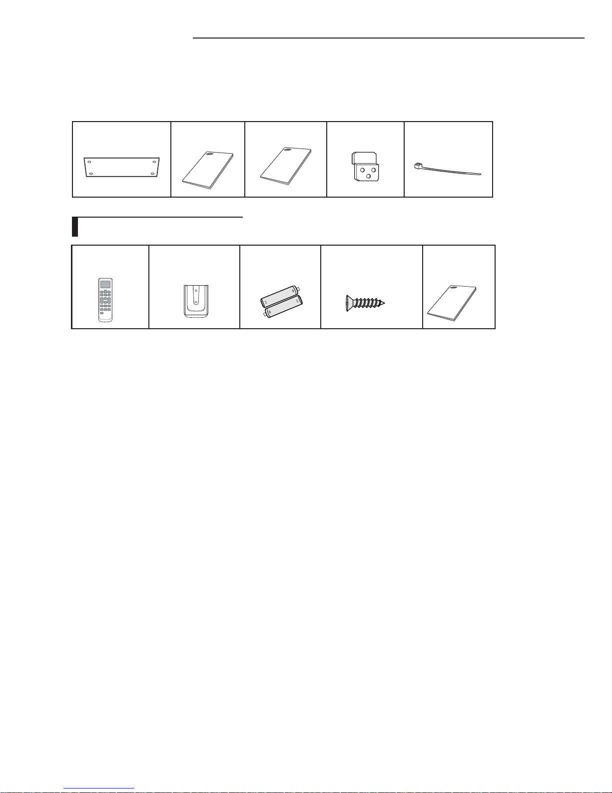
Accessories
The following accessories are supplied with the indoor unit.
The type and quantity may differ depending on the specifications.
Pattern sheet
User manual Installation manual
Plate Hanger
Cable-Tie
Wireless Remote
Controller
Remote Controller
Holder
Battery
M4 X 16 Tapped
Screw
Installation
manual
Wireless Remote accessories
5
ENGLISH
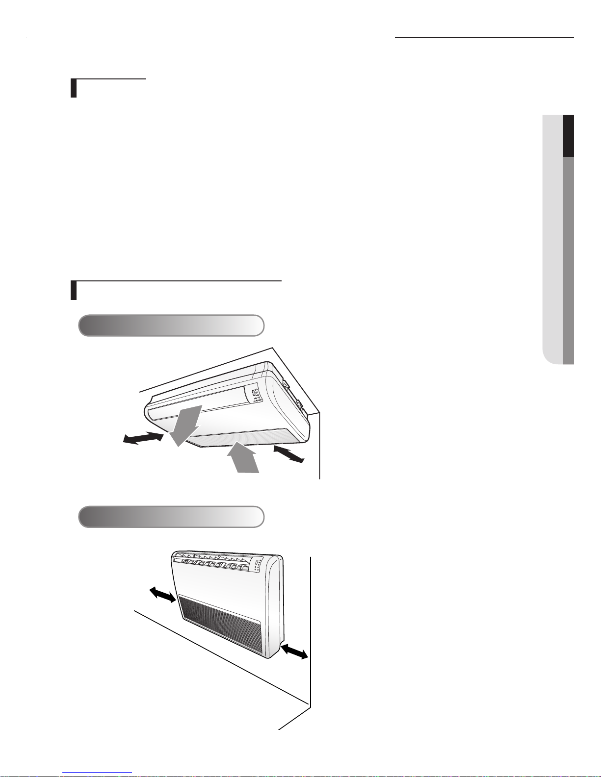
Selecting the installation location
Select a convenient location that permits the air to reach every corner of the area to be cooled.
Pre-plan for easy and short routing of the refrigerant tubing and wiring to the outdoor unit.
There should be no flammable gas, alkaline, substances present in the air.
Avoid location where obstacles preventing good air circulation are present.
Noise prevention should be considered in determining the unit's location.
The structure, where the unit is to be installed should be strong enough to support the weight of the
unit.
Rigid wall without vibration.
Where it is not exposed to direct sunshine.
Where the air filter can be removed and cleaned easily.
Floor installation
300mm
300mm
Ceiling installation
300mm
50mm
Indoor Unit
Space Requirements for Indoor Unit
6
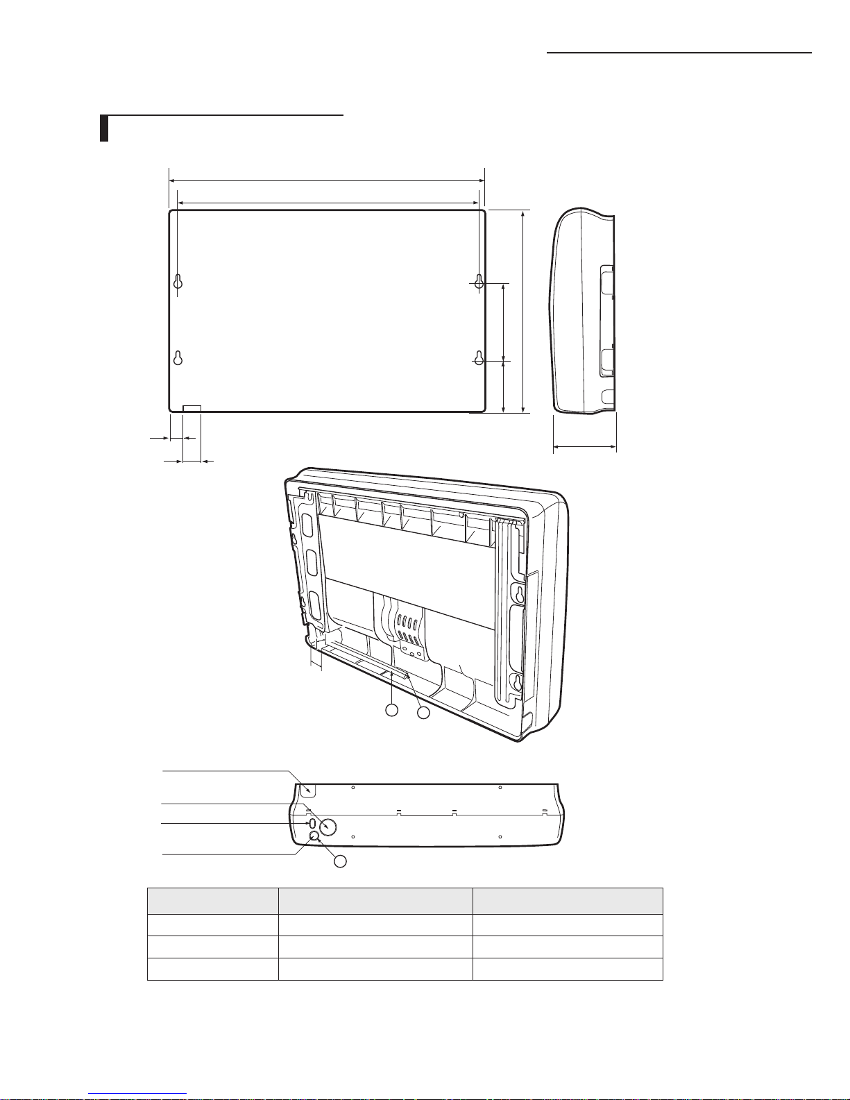
Selecting the installation location
Unit : mm
Back side
P ip e o u tle t
(b o tt o m s id e )
A ir in ta k e h o le ( 5 0 )
W irin g h o le
D ra in h o se o u tle t
2
1
3
Pipe outlet-(bottom side)
Drain hose outlet
Wiring hole
Air intake hole (Ø50)
No. Name Description
1 Liquid pipe connection
ø6.35 (1/4”)
2 Gas pipe connection
ø12.70 (1/2”)
3 Drain pipe connection
ID ø
18 Hose
1000
922
197 240
650
200
45
50
50
44
Dimension of the indoor unit
7
ENGLISH
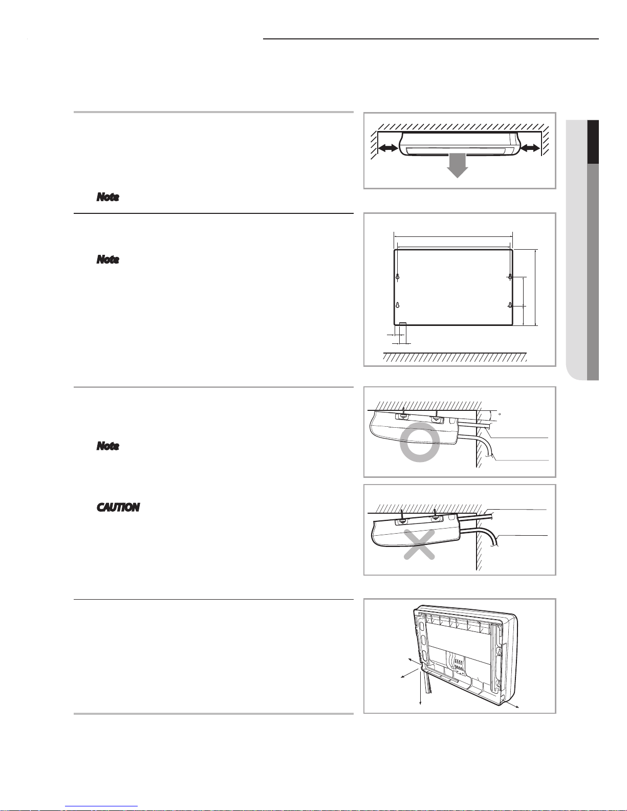
Ceiling installation
2
Connection pipe
Drain hose
Connection pipe
Drain hose
300mm or more
300mm or more
It is recommended to install the Y-joint before installing the
indoor unit.
1
Select pipe directions.
When the directions are selected, drill 3-1/8''-(100mm,
for pipe and cables) and 1-3/4''-(40mm, for drain hose)
diameter holes on the wall so that it slants slightly
downwards toward the outdoor for smooth water flow.
Note Use the pattern sheet to select pipe directions.
2
Drill holes for anchor bolts according to the distance and
mount them.
Note Use the pattern sheet.
3
Install the unit onto the ceiling. Be sure to arrange the
drain hose so that it is leveled lower than the drain hose
connecting port of the indoor unit.
Note For proper drainage of condensate, give a
2° slant to the side of the unit which will be
connected with the drain hose as shown in
the figure.
CAUTION Ensure that the ceiling is strong enough to
support the weight of the indoor unit.
Before hanging the unit, test the strength of
each attached suspension bolt.
4
If installing on dropped ceiling, install threaded rod onto
anchor bolt-(expansion bolt) to long enough to suspend
the unit right below the dropped ceiling and the install
the unit suspending on the threaded rod.
Back side
Unit : mm
1000
922
197 240
650
45
50
8
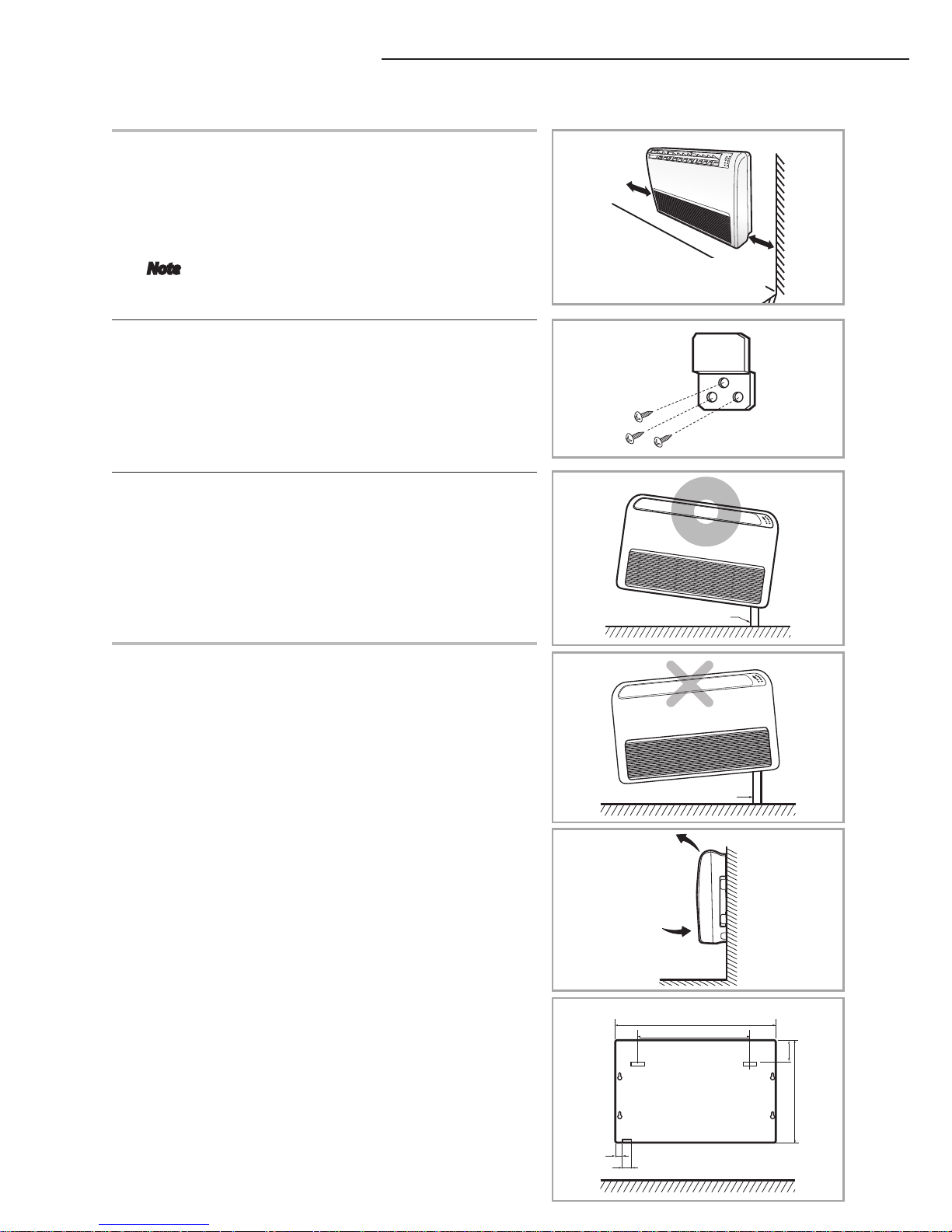
Floor installation
1
Select pipe directions.
When the directions are selected, drill 3-1/8'' (100mm,
for pipe and cables) and 1-3/4'' (40mm, for drain hose)
diameter holes on the wall so that it slants slightly
downwards toward the outdoor for smooth water flow.
Note Use the pattern sheet to select pipe directions.
2
Install the hanging plate according to the distance and
mount it.
3
Install the unit and be sure to arrange the drain hose so
that it is leveled lower than the drain hose connecting
port of the indoor unit.
Drain hose
Drain hose
300mm
or more
300mm
or more
101
650
793
1000
45
50
Back side
Unit : mm
9
ENGLISH
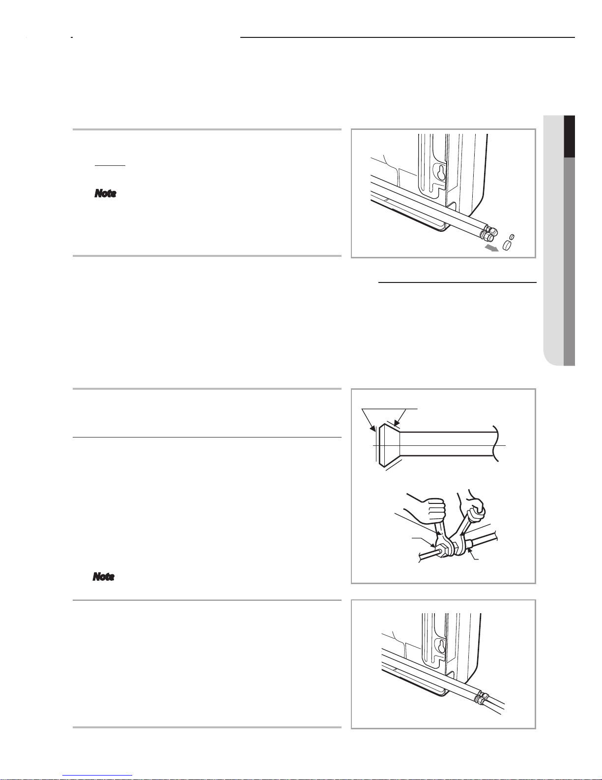
Purging the unit
On delivery, the indoor unit is loaded with an inert Nitrogen
gas. All this gas must therefore be purged before connecting
the assembly piping. To purge the inert gas, proceed as follows.
1
Unscrew the caps at the end of each pipe.
Result: All inert gas escapes from the indoor unit.
Note To prevent dirt or foreign objects from getting
into the pipes during installation, do NOT
remove the caps completely until you are
ready to connect the piping.
There are two refrigerant pipes of differing diameters:
A smaller one for the liquid refrigerant
A larger one for the gas refrigerant
The inside of copper pipe must be clean & has no dust.
1
Before connecting the refrigerant pipe, open the cover
side.
2
Remove the pinch pipe on the pipes and connect the
assembly pipes to each pipe, tightening the nuts, first
manually and then with a torque wrench, a spanner
applying the following torque.
Outer Diameter Torque (kgf•cm)
6.35 mm (1/4") 145~175
9.52 mm (3/8") 333~407
12.70 mm (1/2") 505~615
15.88 mm (5/8") 630~769
Note Must apply refrigerant oil on the flaring area to
prevent a leak.
3
Be sure that there must be no crack or kink on the bended
area.
Refrigerant oil
Torque wrench
Flare nut
Union
Spanner
Connecting the refrigerant pipe
 Loading...