

Samsung MXD-K025AN, MXD-K075AN, MXD-K050AN, MXD-K100AN Installation Manual
NASA PJT_AHU Kit_MXD-K@@@AN Series_EN_03711A(1).indd 40 2013-01-11 오후 3:20:36
Air Conditioner
installation manual
imagine the possibilities
Thank you for purchasing this Samsung product.
To receive more complete service, please
register your product at
www.samsung.com/register
Air Handling Unit
Application Kit
MXD-K025AN
MXD-K050AN
MXD-K075AN
MXD-K100AN
DB68-03711A(1)
EN
NASA PJT_AHU Kit_MXD-K@@@AN Series_EN_03711A(1).indd 41 2013-01-11 오후 3:20:37

2
Contents
SAFETY INFORMATION
...................
3
EXTERNAL APPEARANCE
.............
5
• External Appearance
...........................
5
ACCESSORIES
.....................................
6
• Accessories
...........................................
6
BEFORE INSTALLATION
...................
7
• AHU-KIT Structure Diagram
................
7
• Recommended AHU Size
...................
7
INSTALLATION
.....................................
8
• Control-KIT Installation ...................... 8
• Control-KIT Function ......................... 9
• Control-KIT Circuit Diagram .............. 10
• External Controller Diagram .............. 11
• Simple BMS ...................................... 11
• Connecting the Power Terminal ........ 13
• Control-KIT Connections .................. 14
• Brazing the Pipe ................................ 14
• EEV-KIT Installation ........................... 15
• IN/OUT Sensor Installation ................ 16
FUNCTION SETTING
.........................
19
• Setting an indoor unit address and
installation option .............................. 19
TROUBLESHOOTING
.......................
28
• Initial Check-up ................................. 28
• EEPROM Error .................................. 28
• Sensor Error ..................................... 29
• Fan Error ........................................... 31
• How to Inspect Just in Case
the Below Condition is Satisfied ......... 32
• In-tracking Error ................................ 33
AFTER INSTALLATION
......................
35
• AHU-KIT Installation Check ............... 35
• Test Operation .................................. 36
NASA PJT_AHU Kit_MXD-K@@@AN Series_EN_03711A(1).indd 2 2013-01-11 오후 3:20:22
3
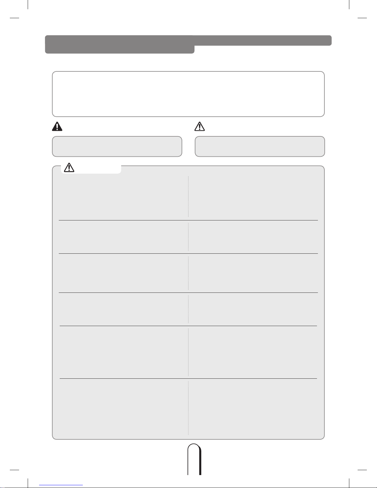
The following safety precautions must be taken when installing the unit.
Be aware that AHU-KIT has to be combined with DVM S Series outdoor unit only.
SAFETY INFORMATION
Risk of death or serious personal injury. Potential risk of personal injury or material
damage.
Use R410A refrigerant.
When using R410A, moisture or foreign substances may affect the capacity and reliability of the product.
Safety precautions must be taken when installing the refrigerant pipe.
R410A is a quasi-azeotrope of two refrigerants. Make sure to charge liquid one when adding refrigerant.
(If you charge gaseous refrigerant, it may affect the capacity and reliability of the product as a result of
change in formation of the refrigerant.)
Turn off the power before installation,
service, and cleaning.
The installation must be done by the
manufacturer or its service agent or a
similar qualified person in order to avoid a
hazard.
Installation by an unqualified person may cause a
water leakage, electric shock or fire .
Use only rated parts and tools.
If you don’t use the rated parts and tools, it can
cause trouble with the product and bring about
injury.
When adding the refrigerant, use the
R410A refrigerant only.
If any gas or impurities except R410A refrigerant
come into the refrigerant pipe, serious problem
may occur and it may cause injury.
Install the outdoor unit correctly according
to the installation manual.
An incorrect installation may cause a water
leakage, electric shock or fire and so on.
Manufacturer is not responsible for
accidents due to incorrect installation by
unqualified person.
Use the pipe or flare part for R410A
refrigerant only.
When there were leakage during installation,
you must ventilate the area.
Toxic gas may generate when refrigerant gas
contacts with fire.
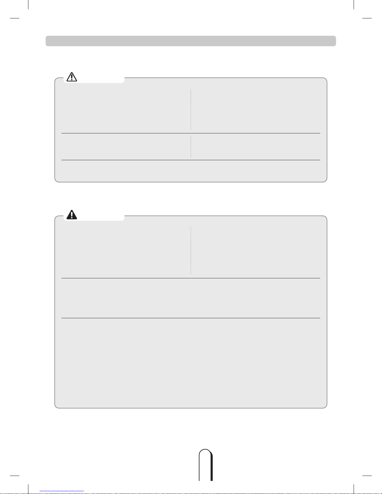
If the power cable or cord is damaged, the
manufacturer, a qualified service technician
must replace it to avoid a potential risk.
The electric work must be done by service
agent or similarly qualified persons
according to national wiring regulations
and use only rated cable.
If the capacity of the power cable is insufficient or
electric work is not properly completed, electric
shock or fire may occur.
Arrange the cables between the AHU-KIT
and outdoor unit after connecting.
Attach the cover securely so that the
electrical component box cover does not
get loosen.
If the cover is attached incompletely, it can cause
trouble with a heat generation, electric shock or
fire of the terminal board.
Install designated ELB for AHU when
installing the power cable.
If you do not install designated ELB for AHU,
electric shock or fire may occur.
WARNING CAUTION
CAUTION
NASA PJT_AHU Kit_MXD-K@@@AN Series_EN_03711A(1).indd 3 2013-01-11 오후 3:20:22
4
Use the copper wire for the power cable
and use only rated cables and parts.
Make sure electrical circuit is correctly
connected.
Overheating may cause fire.
Install the cables with supplied cables
firmly. Fix them securely so that external
force is not exerted to the terminal board.
If the connection or fixing is incomplete, it can
cause trouble with a heat generation, electric
shock or fire.
Make sure that the power for AHU-KIT
is under maximum, and over minimum
voltage allowed.
It may cause electrical component malfunction
which can damage the product.
Make sure there is no leakage after installation.
Toxic gas may generate when refrigerant gas contacts with fire.
Make sure of a earthing.
Do not connect the earth wire to the gas pipe,
water pipe, lighting rod or telephone wire.
If earthing is incomplete, electric shock or fire
may occur.
Follow the instructions in this manual
to make sure that the condensed water
dripping from the drain hose runs out
properly and insulate the drain pipe so
that dew condensate does not generate.
Household goods may get wet if the drain pipe
is not properly installed.
Do not install the AHU-KIT in following places.
The place where there is mineral oil or arsenic acid.
- There is a chance that parts may get damaged due to burned resin.
The place where corrosive gas such as sulfurous acid gas generates from the vent pipe or air outlet.
- The copper pipe or connection pipe may corrode and refrigerant may leak.
The place where there is a machine that generates electromagnetic waves.
- The air conditioner may not operate normally due to control system.
The place where there is a danger of existing combustible gas, thinner or gasoline is handled.
- The place where carbon fiber or flammable dust is.
The place where like spa and shore.
The place with direct contact of sunlight, rain, outdoor humidity, dust and temperature.
Install the power cable and communication cable of the AHU-KIT at least 1m away from
electric appliances.
Noise may heard depending on the electric wave though the cables are installed away from electric
appliances.
Keep the space in front of AHU-KIT for maintenance.
The manufacturer is not responsible for the damage occurred by not keeping standard of the installation.
SAFETY INFORMATION (Continued)
CAUTION
WARNING
NASA PJT_AHU Kit_MXD-K@@@AN Series_EN_03711A(1).indd 4 2013-01-11 오후 3:20:22
5
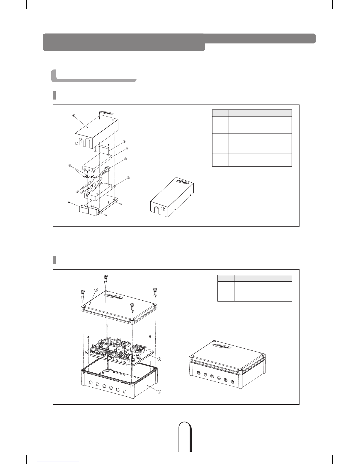
EXTERNAL APPEARANCE
External Appearance
EEV-KIT
Control-KIT
No. Parts and components
1
EEV body
(Coil wire : 2.5/5.0 HP = 2 m
7.5/10.0 HP = 7 m)
2 Lower insulation
3 Upper insulation
4 Holder
5 Cover
6 Clamp
No. Parts and components
1 Controller board
2 Case
3 Cover
NASA PJT_AHU Kit_MXD-K@@@AN Series_EN_03711A(1).indd 5 2013-01-11 오후 3:20:22
6
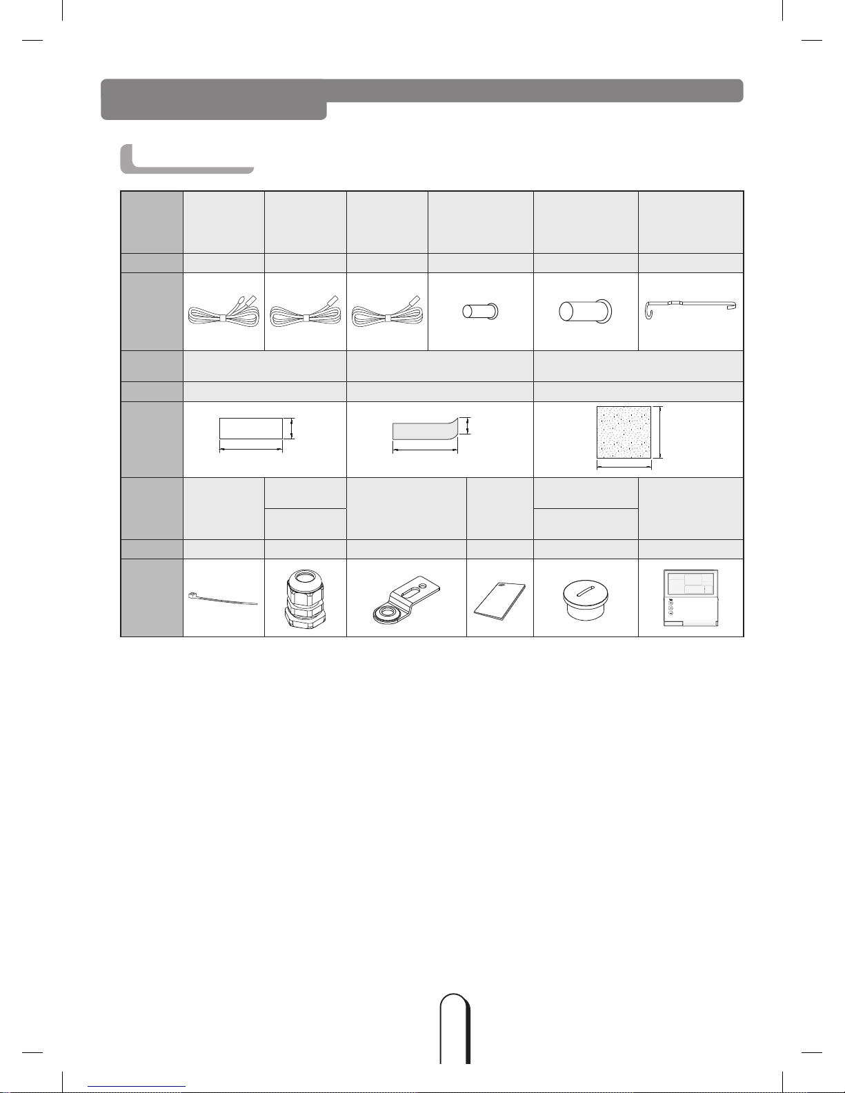
Accessories
ITEM
Room/IN
sensor
(10m)
OUT sensor
(10m)
Disch. sensor
(10m)
IN sensor holder
(OD Ø6.8mm)
OUT sensor holder
(OD Ø7.8mm)
Sensor clip
QUANTITY 1 1 1 1 1 2
IMAGE
ITEM Aluminum tape Rubber tape Insulator
QUANTITY 4 2 2
IMAGE
110㎜
85㎜
110㎜
85㎜
170㎜
100㎜
ITEM Cable-tie
Cable-nut
Bracket Base
Installation
Manual
Screw plug
Wired Remote
Controller
(optional)
PG16 PG16
QUANTITY
8 6 4 1 2
1
IMAGE
ACCESSORIES
NASA PJT_AHU Kit_MXD-K@@@AN Series_EN_03711A(1).indd 6 2013-01-11 오후 3:20:23
7
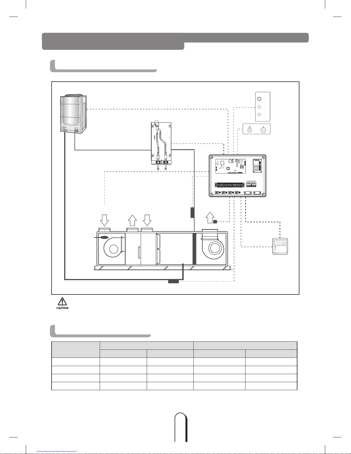
AHU-KIT Structure Diagram
Supply Air
Fresh AirReturn Air Exhaust Air
Outdoor Unit
EEV Kit
EEV Control
Eva_in
Sensor
Eva_out Sensor
Gas pipe
Liquid pipe
Communication F1, F2
Simple BMS
(field supply)
External Controller
(field supply)
Room Sensor
Remote Controller
(optional)
ON/OFF SWITCH
OPERATION LAMP
ERROR LAMP
COOLING HEATING
POWER-OFF
18℃
19℃
20℃
21℃
22℃
23℃
24℃
25℃
26℃
27℃
28℃
Dish. sensor coptional
3
8NC
RY75 RY76 RY77
1
8NC
1(L) 1(N)
Recommended AHU Size
AHU-KIT MODEL
AHU Capacity Allowance (㎾)
AHU Internal Heat Exchanger Volume Allowance (㎤)
Minimum Maximum Minimum Maximum
MXD-K025AN 7 8.75 1,200 1,500
MXD-K050AN 14 17.5 2,150 2,688
MXD-K075AN 21 26.25 3,100 3,875
MXD-K100AN 28 35 4,000 5,000
※Evaporating Temperature : 7 ˚C, Superheat : 1˚C, Air temperature :27 ˚CDB/19 ˚CWB
BEFORE INSTALLATION
• When the controllers (External Controller, simple BMS, Remote Controller) are installed simultaneously,
AHU-KIT doesn’t have the priority of control and operates according to the final signal.
(SIMPLE BMS may indicate the different condition of AHU, if AHU was controlled by other controller finally.)
NASA PJT_AHU Kit_MXD-K@@@AN Series_EN_03711A(1).indd 7 2013-01-11 오후 3:20:23
8
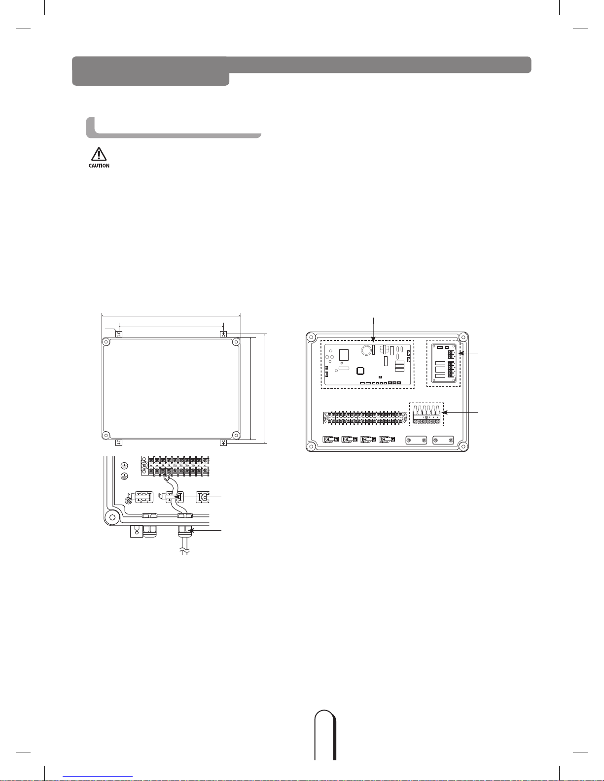
Control-KIT Installation
1) Drill 4 holes on the correct position of the wall and fix the Control-KIT securely.
(refer to the dimension of figure below.)
2) Open the box and connect the cables according to the diagram.
( Wires should be pulled through the Cable-nut, before connecting to the terminal.
Refer to the figure below.)
3) Fix the cable firmly with Cable-tie after connecting.
4) Close the box.
INSTALLATION
3
8NC
RY75 RY76 RY77
1
8NC
1(L) 1(N)
External Controller
(MIM-B14)
Main PBA
Terminal Block
1 2 3 4 1 2 3 4 1 2 3 4
Cable-tie
Cable-nut
• Make sure that Control-KIT should be installed within short distance from the EEV-KIT.
- Supplied sensor in the Accessory box is 10 m.
- 2.5/5.0HP EEV wire is 2 m
- 7.5/10.0HP EEV wire is 7 m
• Close the box with the cover and cable-nut securely so that Control-KIT is fireproofed.
• Avoid installing the unit in a location exposed to direct sunlight or rain.
286
280
300
380
ø4.5
(Unit : mm)
NASA PJT_AHU Kit_MXD-K@@@AN Series_EN_03711A(1).indd 8 2013-01-11 오후 3:20:24

9
Control-KIT Function
• Control-KIT uses EEV to control the amount of refrigerant flow and controls the system through outdoor unit and
wired remote controller.
• Control-KIT outputs the contact signal for AHU fan operation.
Terminal block 1, 2 (Refer to page 10) outputs the AHU fan ON contact signal (220~240V) for AHU when operating
in Cool/Heat/Fan mode. This contact signal output can not be used as power supply for the motor.
• Terminal block 3, 4 (Refer to page 10) is for AHU-KIT control to receive the fan operation status. This input signal
should be simple OPEN/SHORT signal without any extra voltage.
- Normal fan operation : Terminal block 3, 4 is in SHORT.
- Fan is not in operation : Terminal block 3, 4 is in OPEN.
- To use fan feedback to protect your system, set the function switch K12(Refer to page 21) to OFF position.
• Connect 220~240V 50/60Hz to terminal block 1(L)/2(N).
• You should connect outdoor unit communication cable to communication line (F1, F2)(Refer to page 10).
• F3, F4(Refer to page 10) is communication line for wired remote controller(12 V).
INSTALLATION (Continued)
NASA PJT_AHU Kit_MXD-K@@@AN Series_EN_03711A(1).indd 9 2013-01-11 오후 3:20:24
10
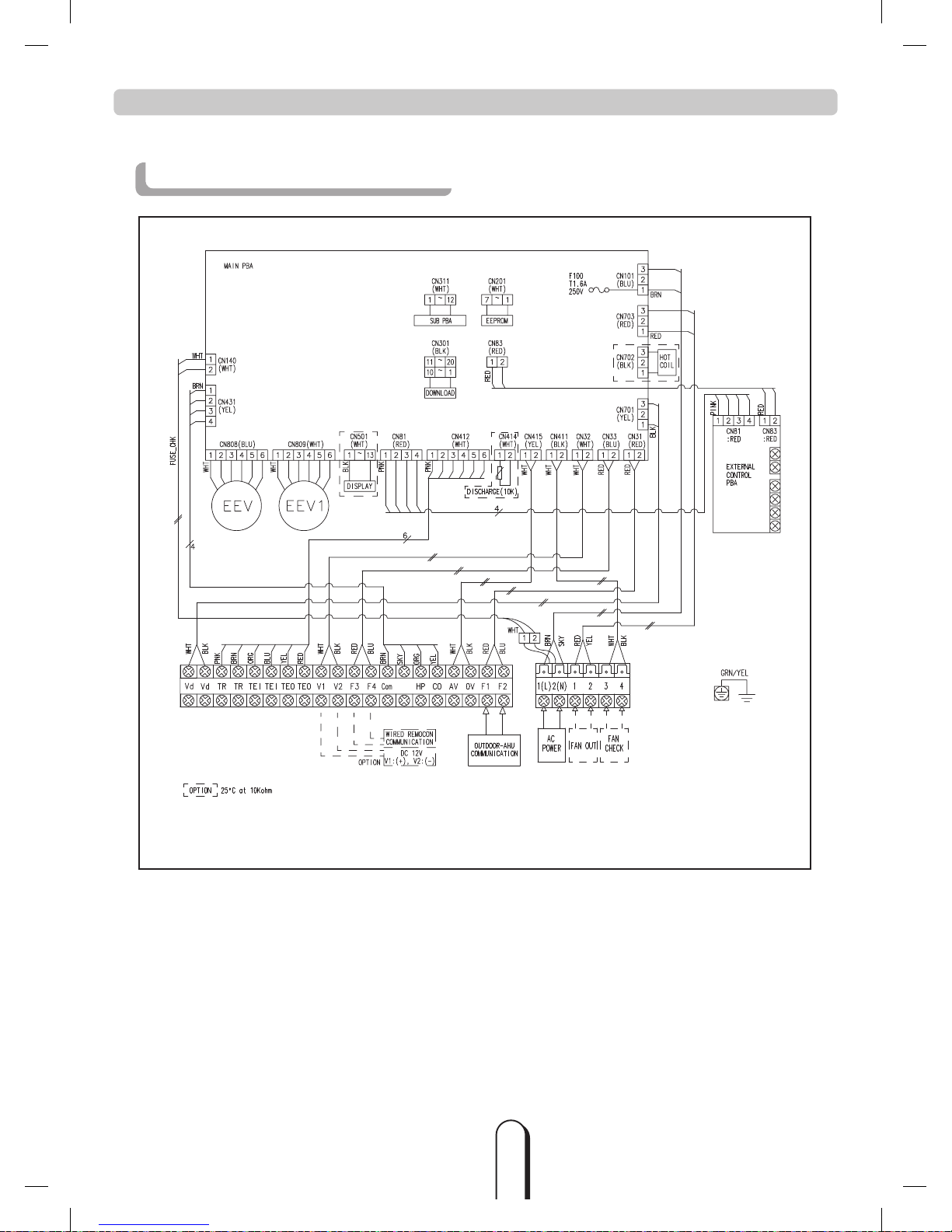
Control-KIT Circuit Diagram
AHU-KIT sensor has approximately 10㏀ of resistance value at indoor temperature of 25˚C.
INSTALLATION (Continued)
NASA PJT_AHU Kit_MXD-K@@@AN Series_EN_03711A(1).indd 10 2013-01-11 오후 3:20:25
11
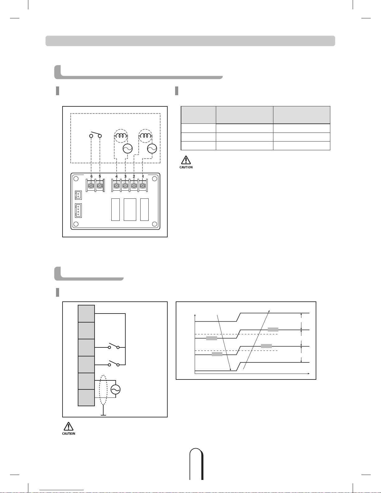
External Controller Diagram (MIM-B14)
Circuit diagram of external
controller’s output
S/W
38NC
GND
RY75 RY76 RY77
18NC
AC LAMP
INSTALLATION (Continued)
Operation specification according to
AHU-KIT PBA Install option set up
WIRE NO. Signal Install option
1, 2 Error check output -
3, 4 Operation check output SEG 15
5, 6 ON/OFF input SEG 14
•
In order for AHU-KIT to be controlled by External control,
change a digit of indoor unit installation option,
set the SEG14 as “1”. (ON / OFF control)
Simple BMS
Circuit diagram of Simple BMS
COM
HP
CO
AV
OV
Shielding
EX) setting up 22℃
[Voltage]
decreasing temperature
increasing temperature
4.8V
4.6V
4.4V
4.65V
4.25V
4.55V
4.95V
The areas of 23℃
The areas of 22℃
The areas of 21℃
• Hysteresis is applied to the end of voltage range in order to stabilize the analog input.
The amount of Hysteresis : 0.15V
NASA PJT_AHU Kit_MXD-K@@@AN Series_EN_03711A(1).indd 11 2013-01-11 오후 3:20:25
 Loading...