

Samsung MOSCON-E7 User Manual

PREF ACE
Thank for purchasing small general-purpose
multi-functional inverter MOSCON-E7.
MOSCON-E7 is a small and easy to use inverter.
This user’s manual describes installation,
maintenance and inspection, troubleshooting and
specifications of the MOSCON-E7.
Read this user’s manual thoroughly for safe
operation of the system and retain for future
reference.
Samsung Electronics Co., Ltd.
Copyrightⓒ2001 Samsung Electronics Co., Ltd.
MOSCON-E7 is trademarks of Samsung Electronics Co., Ltd.
The software and hardware described i n this manu al is pro tected by the copyright.
No part of this manual may be photocopied or reproduced in part or in whole without the written
consent of Samsung Electronics Co., Ltd.
We will try our best to meet your demands with this manual.
Contact our office stated below in case of bei ng a printing erro r, mistakes and improvement in
this manual.
Contact Office : Samsung Electronics Co., Ltd.
416, Maetan-3 Dong, Paldal-Gu, Suwon City , Kyungki-Do, Korea
TEL : 82-31-200-2489
FAX : 82-31-200-2295
General precautions
• This manual may contain some drawings with the
cover or protective shields removed for more
detail and clear explanation of the device. Make
sure to reassemble the device before operation.
• The information in this manual may be subject to
change without a previous notice in case of
modification or improvement, or changes in
specifications. Such modifications are denoted
by a revised manual number.
• Contact your Samsung representative or the
nearest Samsung sales office to order a copy of
this manual if it has been damaged or lost.
• Samsung is not responsible for any modification
of the product made by the user, since that will
void your guarantee.
This user’s manual uses (Danger), (Caution) or (Note) for the
safety precautions depending on the degree of precautions.
Safety precautions
Installation
• Before starting wiring or inspection, switch power off, wait for
more than 1 minutes, and check for residual voltage between
terminal P/B and N with a meter etc, to avoid a hazard of
electrical shock..
• Do not remove the operator from the main body.
It may cause an electric shock.
• When using the digital operator away from the main body, use the
separated operator(E7OPTR-S).
• Suitable for use in a circuit capable of delivering not more than
5kA rms symmetrical amperes.
DANGER:
Wrong handling may cause a dangerous
situation, which can lead to death or a
severe injury.
!
CAUTION: Wrong handling may cause a dangerous
situation, which can lead to a severe
injury, slight injury, or damage to the
production, or faulty operation
.
!
DANGER
!
Safety precautions
• Do not carry the inverter by holding the plastic parts, but hold the
heatsink.
The heat sink may fall and cause injury.
• Use nonflammable materials such as metal for the part where the
inverter is installed.
• When installing several inverters in a single enclosed space, install
a cooling fan to keep the ambient temperature below 45℃
• Cover the inverter during installation to protect it from metal
chip coming from drilling.
Wiring
• Always turn OFF the input power supply before wiring.
Otherwise, an electric shock or fire may occur.
• Wiring must be performed by qualified personnel.
• Always check if the bolts on the main circuit and control circuit
terminals are properly tightened.
• Turn ON the inverter only after completely assembling the covers.
Do not detach the cover when the power is ON.
Otherwise, an electric shock or fire may occur.
• Ground the ground terminal (200V & 400V class: ground to 100Ω
or less).
Otherwise, an electric shock or fire may occur.
CAUTION
!
DANGER
!
MOSCON E-7 User’s Manual
• Tighten all terminal screws of the main circuit and the control
circuit.
• Check if the voltage of the inverter rated voltage satisfies with the
AC power supply voltage.
Otherwise, it may cause fire or injury
• Do not perform withstand voltage test on the inverter. It may
damage the semi-conductor element.
• When wiring other devices read their manuals carefully. Samsung
is not responsible for any accident resulting from user’s
carelessness.
If not, it may cause injury or fire.
• Do not connect electromagnetic switches or contactors to the
output circuits.
• Never connect an AC power supply to output terminals U/T1,
V/T2, and W/T3.
Otherwise, it may damage the internal circuits of the inverter.
• Never short or ground output terminals: the output terminals
should not be touched with bare hands and also, the output wires
should not have contact with the inverter case
Otherwise, an electric shock or grounding may occur
• Do not connect a phase advancing capacitor or LC/RC noise filter
to an output circuit.
Otherwise, it may damage the inverter or cause a fire.
• Do not connect an electromagnetic switch or MC to an output
circuit.
Otherwise, it will actuate the over current protective circuit in the
inverter.
• Do not disassemble the digital operator.
Otherwise, it may cause a personal injury.
CAUTION
!
Parameter setting
• Set the appropriate parameter. If not, it will not operate or trigger
the protection operation.
• Record the previous parameters (even though Moscon-E7 records
the information of the last parameter), the records can be useful
in case of malfunction or errors.
• When changing the parameters, make small change at a time
especially when controlling the motor parameter, changing the
V/f or max. output frequency. If not, it may damage the
inverter and motor.
CAUTION
!
Safety precautions
MOSCON E-7 User’s Manual
Maintenance and inspection
• Do not remove the digital operator from the unit since it carries
high voltages. Using the cable between operator and unit is also
prohibited, since it is very dangerous.
• Do not touch the terminals since some of them carry high
voltages and are extremely dangerous.
Otherwise, it may cause an electric shock.
• Do not remove the cover when power is being supplied to the
inverter. Always turn off the power to the inverter through the
MCCB when detaching the cover.
Otherwise, the charge remained in the capacitor may cause an
electric shock.
• After turning off the main circuit power supply, wait for a while
before maintenance or inspection since it may remain charged.
Otherwise, it may cause an electric shock.
• Maintenance, inspection, and replacement of parts must be done
only by authorized personnel.
Otherwise, it may result an injury or an accident.
• Remove all metal objects, such as watches and rings, before the
maintenance, inspection, and replacement of parts. Also, always
use grounded tools.
Otherwise, it may cause an electric shock.
• Always turn off the power supply before the inspection
Otherwise, it may cause an electric shock.
DANGER
!
Safety precautions
• Do not touch the COMOS IC in the control board directly.
Otherwise it can be damaged by static electricity.
• Do not change the wiring, or remove the digital operator or
connectors, during operation.
Otherwise, it may cause a personal injury.
CAUTION
!
MOSCON E-7 User’s Manual

Contents -1
Contents
1.Overview
---------------------------------------------------------------------------------------- 1-1
1.1 Main features ------------------------------------------------------------------------------------ 1-3
1.2 System diagram -------------------------------------------------- ---------------------------- 1-5
1.3 Dimensions ---------------------------------------------------------------------------------------- 1-6
1.4 Specifications ------------------------------------------------------------------------------------- 1-8
2. Installation ----------------------------------------------------------------------------------- 2-1
2.1 Receiving ---------------------------------------------------------- --------------------------------- 2-3
2.2 Nameplate information --------------------------------------------------------------- 2-4
2.3 Installation ---------------------------------------------------------------------------------------- 2-5
2.3.1 Precautions for delivery and installation ------------------------------------------------------- 2-5
2.3.2 Installation site --------------------------------------------------------------------------------------- 2-6
2.3.3 Controlling the ambient temperature -------------------------------------------------------- 2-7
2.3.4 Installation space ------------------------------------------------------------------------------------ 2-8
3. Wiring ---------------------------------------------------------------------------------------------- 3-1
3.1 Connection diagram --------------------------------------------------------------------- 3-4
3.2 Terminal block configuration
---------------------------------------------------- 3-6
3.3 Main circuit terminal functions ------------------------------------------------ 3-7
3.4 Control circuit terminal functions ------------------------------------------- 3-8
3.5 Connections to peripheral devices ------------------------------------------- 3-9
3.6 Wiring the main circuits -------------------------------------------------------------- 3-1 0
3.6.1 Wiring on the input side of main circuit ----------------------------------------------------- 3-10
3.6.1.1 Installing a molded-case circuit breaker --------------------------------------------------------- 3-10
3.6.1.2 Installing a magnetic contactor(MC) --------------------------------------------------------- ---------- 3-10
3.6.1.3 Installing an AC reactor/DC reactor ------------------------------------------------------------ 3-11
3.6.1.4 Connecting input power supply --------------------------------------------------------------------- 3-12
3.6.1.5 Installing a surge absorber ------------------------------------------------------------------------- 3-12
3.6.1.6 Installing a noise filter on power supply side --------------------------------------------------- 3-13
3.6.2 Wiring on the output side of main circuit --------------------------------------------------- 3-15
3.6.2.1 Precautions when wiring on the output side of main circuit ----- -------------------------- 3-15
3.6.2.2 Connecting the inverter and motor -------------------------------------------------------------- 3-15
3.6.2.3 Installing a noise filter on the output side ------------------------------------------------------- 3-15
2 - MOSCON-E7 U ser’s Manual
3.6.3 Dealing with inductive noises ------------------------------------------------------------------- 3-16
3.6.4 Dealing with radio interference (RFI) -------------------------------------------------------- 3-16
3.6.5 Cable length between inver ter and motor ---------------------------------------------------- 3-17
3.7 Precautions when wiring -------------------------------------------------------------- 3-18
3.7.1 Control circuit wiring precautions -------------------------------------------------------------- 3-18
3.7.2 Main circuit input/output wiring --------------------------------------------------------------- 3-18
3.8 Grounding ---------------------------------------------------------------------------------------- 3-20
3.9 Cable specification ---------------------------------------------------------------------------------- 3-21
3.10 Wiring check
------------------------------------------------------------------------------------ 3-22
4 Digital operator ------------------------------------------------------------------------- 4-1
4.1 Usage of digital operator -------------------------------------------------------------- 4-4
4.2 Monitoring functions of digital operator -------------------------------- 4-5
4.3 Test run ---------------------------------------------------------------------------------------------- 4-6
5 Parameters ------------------------------------------------------------------------------ 5-1
5.1 Main feature ------------------------------------------------------------------------------------- 5-3
5.1.1 U-parameter : monitoring function ------------------------------------------------------------- 5-4
5.1.2 Monitoring function setting ---------------------------------------------------------------------- 5-8
5.2 Terminal status LED --------------------------------------------------------------------- 5-9
5.3 B-Parameter -------------------------------------------------------------------------------- 5-10
5.3.1 Basic setup ---------------------------------------------------------------------------------------------- 5-10
5.3.1.1 Sel ecting the source of frequency command : B0.01 -------------------------------------------------- 5-10
5.3.1.2 Selecting the source of RUN command : B0.02 ------ ---------------------------------------------- 5-10
5.3.1.3 S electing stopping method : B0.03 ----------------------------------------------------------------- 5-11
5.3.1.4 Prohibiting the reverse rotation : B0.04 --------- ------------------------------------------------------ 5-11
5.3.1.5 Setting the motor direction : B0.05 ---------------------------------------------------------------- 5-12
5.3.1.6 Setting the monitor default : B0.06 ----------------------------------------------------------------- 5-12
5.3.1.7 Setting the automatic start operation : B0.07 ------------------------------------------------------- 5-12
5.3.2 System initialization ----------------------------- ---------------------------------------------------- 5-13
5.3.2.1 Controlling the inverter initialization : B1.01 ---------------------------------------------------------- 5-13
5.3.2.2 Setting and verifying the password : B1.02, B1.03 ---------------------------------------------- 5-14
5.3.3 Setting power capacity ------------------------------------------------------------------------5-14
5.3.3.1 Setting the inverter and motor capacity : B2.01, B2.02 ---------------------------------------- 5-14
5.4 F-Parameter -------------------------------------------------------------------------------------- 5-15

Contents -3
5.4.1 Frequency control functions --------------------------------------------------------------- 5-15
5.4.1.1 Setting the frequency/speed command: F0.01~F0.09 -------------------------------- 5-15
5.4.2 Frequency limit --------------------------------------------------------------------------------- 5-16
5.4.2.1 Setting lower/upper frequency limit : F1.01,F1.02 ------------------------------------- 5-16
5.4.3 Jump frequency to avoid mechanical resonant oscillation ---------------------- 5-16
5.4.3.1 Setting jump frequency : F1.03~F1.06 ---------------------------------------------------- 5-16
5.4.3.2 Selecting the jump mode : F1.07 ----------------------------------------------------------- 5-17
5.4.4 Frequency match detection ---------------------------------------------------------- 5-19
5.4.4.1 Controlling the frequency detection : F1.08. F1.09 --------------------------------------- 5-19
5.4.4.2 Automatic activation of 2nd accel/decel time : F1.10 ---------------------------------- 5-19
5.4.5 accel/decel time ----------------------------------------------------------------------------- 5-20
5.4.5.1 Setting the accel/decel time : F2.01~F2.04 ---------------------------------------------- 5-20
5.4.5.2 Setting the time unit of accel/decel time : F2.05 --------------------------------------- 5-20
5.4.6 Configuring S-curve time : F3.01 --------------------------------------------------- 5-21
5.5 S-Parameter ------------------------------------------------------------------------------ 5-22
5.5.1 DC braking ---------------------------------------------------------------------------- 5-22
5.5.1.1 Controlling DC breaking : S0.01~S0.04 ------------------------------------------------------ 5-22
5.5.2 Speed search ----------------------------------------------------------------------------------- 5-23
5.5.2.1 Controlling the speed search operation : S1.01 ------------------------------------------------ 5-23
5.5.2.2 Speed search level, current and deceleration time --------------------------------------- 5-23
5.5.3 Dwell operation -------------------------------------------------------------------------------- 5-25
5.5.3.1 Controlling the dwell operation : S2.01~S2.04 ----------------------------------------------- 5-25
5.5.4 Energy saving function ---------------------------------------------------------------------- 5-26
5.5.4.1 Setting the energ y saving level : S3.01 ------------------------------------------------------ 5-26
5.5.4.2 Setting the energy-saving frequency : S3.02 ----------------------------------------------- 5-26
5.5.5 Slip compensation ----------------------------------------------------------------------------- 5-27
5.5.5.1 Setting the slip compensation gain : S4.01 ------------------------------ ------------------ 5-27
5.5.5.2 Setting the slip compensation delay : S4.02 ----------------------------------------------- 5-27
5.5.5.3 Slip compensation limit : S4.03 -------------------------------------------------------------- 5-27
5.5.6 Automatic torque boost --------------------------------------------------------------------- 5-29
5.5.6.1 Torque compensation gain : S5.01 ----------------------------------------------------------- 5-29
5.5.6.2 Torque compensation delay : S5.02 --------------------------------------------------------- 5-29
5.5.7 System function compensation ------------------------------------------------------------ 5-30
5.5.7.1 Hunting prevention gain : S6.01 ------------------------------------------------------------- 5-30
5.5.7.2 Boosting brake performance : S6.02 --------------------------------------------------------- 5-3 0
4 - MOSCON-E7 U ser’s Manual
5.6 C-Parameter : H/W functionality setup ----------------------------- 5-31
5.6.1 V/f setting ----------------------------------------------------------------------------------------- 5-31
5.6.1.1 Setting V/f : C0.01 -------------------------- -------------------------------------------------------------- 5-3 1
5.6.1.2 Setting user-programmable V/f pattern ------------------------------------------------------------ 5-37
5.6.2 Carrier frequency setting ------------------------------------------------------------------ 5-38
5.6.2.1 Setting the carri er frequency : C1.01 ----------------------------------------------------------- ------- 5-38
5.6.3 Main motor constants ------------------------------------------------------------------------------------ 5-38
5.6.3.1 Setting the motor line-to-line resistance : C2.01 ------------- --------------------------------------- 5-38
5.6.3.2 Setting the iron loss : C2.02 ------------------------------------------------------------------------------ 5-38
5.6.3.3 Setting the motor rated cur rent : C2.03 -------------------------------------------------------------- 5-39
5.6.3.4 Motor no-load current : C2.04 ----------------------------------- -------------------------------------- 5-39
5.6.3.5 Setting the motor rated slip : C2.05 ----- --------------------------------------------------------------- 5-39
5.6.4 H/W Adjusting data : C3.01~C3.06 ------------------------------------------------------------ 5-40
5.7 H-Parameter : I/O contro l functions ---------------------------------------------- 5-41
5.7.1 Multi-function contact input --------------------------------------------------------------------------- 5-41
5.7.1.1 Set input type of multi-function contact input : H0.01 ----------------------------------------- 5-41
5.7.1.2 Setting the function of contact input : H0.02~H0.05 ----------------------------------------- -- 5-41
5.7.2 Multi-function contact output --------------------------------------------------------------- 5-50
5.7.2.1 Set output type of multi-function output : H1.01 ---------------------------------------------- 5-50
5.7.2.2 Setting the function of multi-function output : H1.02 -------------------------------------- 5-50
5.7.3 Multi-function analog input --------------------------------------------------------------------------- 5-52
5.7.3.1 Analog input form : H2.01 --------------------------------------------------------------------------- 5-52
5.7.3.2 Analog input filter time constant : H2.02 --- --------------------------------------------------- ---- 5-52
5.7.3.3 Adjusting analog inputs : H2.03, H2.04, H2.06, H2.07 ------------------------------------------ 5-53
5.7.3.4 Setting the multi-function analog input ter minal function : H2.05 ---------------------------- 5-54
5.7.4 Multi-function analog output : H3.01~H3.03 ------------------------------------------------------- 5-55
5.7.4.1 Setting multi-function analog output : H3.01 ---------------------------------------------------- 5-55
5.7.4.2 Adjusting the monitor o utput : H3.02, H3.03 --------------------------- -----------------------------5-56
5.7.5 Digital operator setting -------------------------------------------------------------------------------------5-57
5.7.5.1 Setting the display format in U0.07 : H4.01 ------------------------------------------------ 5-57
5.7.5.2 Setting the STOP key enable/disable : H4.02 -------------------------------------------------- 5-57
5.7.5.3 Setting the operation when switching REMOTE→LOCAL : H4.03 ----------------------------5-57
5.7.5.4 Setting the device ID : H4.04 -------------------------------------------------------------------- 5-58
5.7.5.5 Select frequency unit : H4.05 ------------------------------------------------------------------ 5-58
5.7.5.6 Setting the parameter setting mode : H4.06 ------------------------------------------------- 5-59

Contents -5
5.7.5.7 Setting the fan operating method : H4.07 --------------------------------------------------- 5-59
5.8 P-Parameter : Protective functions -------------------------------------------------- 5-60
5.8.1 Motor overload protection --------------------------------------------------- ------------ 5-60
5.8.1.1 Select motor protection : P0.01 -------------------------------------------------------------------- 5-60
5.8.1.2 Motor protection time constants : P0.02 ----------------------------------------------------------------- 5-61
5.8.1.3 Motor selection: P0.03 ---------------------------------------------- --------------------------------------- 5-62
5.8.2 Momentary power failure -------------------------------------------------------------------------- 5-63
5.8.2.1 Operation at power loss : P1.01 --------------------------------------------------------------------- 5-63
5.8.2.2 Compensation time of power loss : P1.02 ----------------------------- ------------------------- 5-63
5.8.2.3 V/f recovery time : P1.03 -------------------------------------------------------------------------- 5-64
5.8.2.4 : Undervoltage level : P1.04 ------------------------------------------------------------------------ 5-64
5.8.3 Stall prevention ----------------------------------------------------------------------------------------- 5-65
5.8.3.1 Stall prevention at start : P2.01 ---------------------------------------------------------------------- 5-65
5.8.3.2 Stall prevention level at start : P2.02 --------------------------------------------------------------- 5-65
5.8.3.3 Stall prevention limit during acceleration : P2.03 ----------------------------------------------- 5-66
5.8.3.4 Stall prevention at stop : P2.04 --------------------------------------------------------------------- 5-67
5.8.3.5 Stall prevention when the motor is running : P2.05 --------------------------------------- ---- 5-68
5.8.3.6 Stall prevention when the motor is r unning at the desired frequency : P2.06 ------------- 5-68
5.8.4 Overtorque detection : P3.01~P3.03 ----------------------------------------------------------- 5-70
5.8.4.1 Overtorque detection : P3.01 ------------------------------------------------------------------------ 5-70
5.8.4.2 Overtorque detection level & overtorque delay time : P3.02,P3.03 ------------------- ------- 5-71
5.8.5 Fault retry -------------------------------------------------------------------------------------------------- 5-72
5.8.5.1 Number of fault retr y : P4.01 ------------------------------------------------------------------- 5-72
5.8.5.2 Output terminal function during retry : P4.02 ---------------------------------------------- 5-73
5.8.5.3 Fan error : P5.01 ------------------------------------------------------------------------------------ 5-73
5.9 Error monitoring ---------------------------------------------------------------------------- 5-74
6. Troubleshooting ----------------------------------------------------------------------- 6-1
6.1 Protective function/error description ---------------------------------------- 6-3
7. Maintenance and inspection -------------------------------------------- 7-1
7.1 Daily inspection ----------------------------------------------------------------------------------- 7-4
7.2 Periodic inspection --------------------------------------------------------------------------- 7-4
7.3 Part replacement ------------------------------------------------------------------------------ 7-6
6 - MOSCON-E7 U ser’s Manual
-------------------------------------MEMO-------------------------------------

List of figures - 1
List of figures
1.Overview
Figure 1.1 System diagram -------------------------------------------------------------------- 1-5
Figure 1.2 Dimensions of 1 phase 20P4 and 3 phase 20P4, 20P7 ------------------------ 1-6
Figure 1.3 Dimensions of 1 phase 20P7, 21P5 and 3 phase 21P5~22P2, 40P4~41P5 -- 1-6
Figure 1.4 Dimensions of 1 phase 22P2 and 3 phase 23P7, 42P2~43P7 --------------------1-7
2. Installation
Figure 2.1 Example of nameplate ---------------------------------------------------------- 2-3
Figure 2.2 Installation space ------------------------------------------------------------------- 2-8
3. Wiring
Figure 3.1 Connection diagram (200V class) ----------------------------------------- 3-4
Figure 3.2 Connection diagram (400V class) ------------------------------------------- 3-5
Figure 3.3 Terminal configuration ------------------------------------------------------- 3-6
Figure 3.4 Peripheral devices ------------------------------------------------------------- 3-9
Figure 3.5 Reactor installation ---------------------------------------------------------- 3-11
Figure 3.6 Power supply noise filter installation ------------------------------------- 3-14
Figure 3.7 Noise filter on the output side --------------------------------------------- 3-15
Figure 3.8 Dealing with inductive noise ------------------------------------------------- 3-16
Figure 3.9 Dealing with radio interference ----------------------------------------------- 3-16
Figure 3.10 Ends of twisted-pair cables ------------------------------------------------- 3-18
Figure 3.11 Direction of motor’s rotation ------------------------------------------- 3-18
Figure 3.12 Multiple grounding ---------------------------------------------------------- 3-20
4. Digital operator
Figure 4.1 Monitoring functions of digital operator ---------------------------------- 4-5
Figure 4.2 Test run using digital operator ---------------------------------------------- 4-7
5. Parameters
Figure 5.1 Parameter setting method --------------------------------------------------------- 5-7
Figure 5.2 Selecting monitoring group (U) --------------------------------------------------- 5-8
Figure 5.3 Timing chart for multi-step and JOG operation --------------------------- 5-15
Figure 5.4 Upper and lower limits of the frequency reference ------------------------ 5-16
2 - MOSCON-E7 U ser’s Manual
Figure 5.5 Setting jumping frequencies -------------------------------------------------- 5-18
Figure 5.6 Acceleration/deceleration time switching frequency --------------------- 5-19
Figure 5.7 Setting S-curve characteristics ---------------------------------------------- 5-21
Figure 5.8 DC braking timing chart -------------------------------------------------------- 5-22
Figure 5.9 Speed search timing chart -------------------------------------------------------- 5-24
Figure 5.10 Timing chart for dwell function -------------------------------------------- 5-25
Figure 5.11 Slip compensation limit -------------------------------------------------------- 5-28
Figure 5.12.1 V/f pattern : settings 0~14 & setting15 -------------------------------- 5-33
Figure 5.12.2 V/f pattern : settings 0~14 & setting15 ---------------------------------- 5-34
Figure 5.13.1 V/f pattern : settings 0~14 & setting15 ---------------------------------- 5-35
Figure 5.13.2 V/f pattern : settings 0~14 & setting15 ----------------------------------- 5-36
Figure 5.14 User-defined V/f pattern ------------------------------------------------------- 5-37
Figure 5.15 3-wire sequence wiring example ------------------------------------------------ 5-43
Figure 5.16 Time chart for 3-wire sequence ----------------------------------------------- 5-43
Figure 5.17 Using two accel/decel time ------------------------------------------------------ 5-45
Figure 5.18 Acceleration/deceleration jamp hold -------------------------------------------- 5-46
Figure 5.19 Timing chart for up and down commands ------------------------------------- 5-47
Figure 5.20 Timing chart for DC injection braking command ------------------------------- 5-48
Figure 5.21 Timing chart for the external search command ------------------------------- 5-49
Figure 5.22 Gain and bias ------------------------------------------------------------------------- 5-53
Figure 5.23 Monitor output adjustments ----------------------------------------------------- 5-56
Figure 5.24 Motor protection operating time ------------------------------------------------- 5-61
Figure 5.25 Acceleration stall prevention function : P2.01=1 ----------------------------- 5-66
Figure 5.26 Stall prevention limit during acceleration ---------------------------------------- 5-66
Figure 5.27 Deceleration stall prevention function : P2.04=1 ------------------------------ 5-67
Figure 5.28 Run stall prevention function : P3.05=1 or 2 ------------------------------------- 5-69
Figure 5.29 Timing chart for overtorque detection ------------------------------------------- 5-71

List of tables -1
List of tables
1.Overview
Table 1.1 Dimensions of FARA MOSCON-E7 -------------------------------------------- 1-7
Table 1.2 Specifications for 200V class -------------------------- ------------------------------- 1-8
Table 1.3 Specifications for 400V class -------------------------------------------------------- 1-10
3. Wiring
Table 3.1 200V class main circuit terminal functions --------------------- ------------------- 3-7
Table 3.2 400V class main circuit terminal functions ---------------------------- -------------- 3-7
Table 3.3 Cable circuit terminal block -------
---------
---------------------------------------- ----- 3-8
Table 3.4 MCCB and Magnetic Contactor ---------------------------- -------------------------- 3-11
Table 3.5 DC Reactor -------------------------------------------------- ----------------------------- 3-12
Table 3.6 AC Reactor ------------------------------------------------------------ ------------------- 3-12
Table 3.7 Application of the surge absorber ---------------- -------------------------------- ---- 3-13
Table 3.8 Cable length.vs.carrier frequency -------------------------------- -------------------- 3-17
Table 3.9 Cable size -------------------------------------------------------------------------------- 3-21
5. Parameters
Table 5.1 Functions of each group -- ------------------------------------------------------------ 5-3
Table 5.2 Operation status ------------------------------------------------------------------------- 5-4
Table 5.3 Inverter operation status on last fault --------------------------------- -------------- 5-5
Table 5.4 Fault list ---------------------------------------------------------------------------------- 5-5
Table 5.5 Parameter check list -------------------------------------------- ------------------------- 5-5
6. Troubleshooting
Table 6.1 Fau lt dis play a nd cont ents ( Faults in inv erter ) ---- ----- -------- -------------------- 6-3
Table 6.2 Fault display and contents (Warning on inverter) : Blinking display ----------- 6-6
Table 6.3 Fault display and contents (Communication fault) ----------------------------------- 6-7
7. Maintenance and Inspection
Table 7.1 Periodic inspection --------------------------------------------------------------------- 7-5
Table 7.2 Part replacement -------------------------------- ----------------------------------------- 7-6
2 - MOSCON-E7 U ser’s Manual
-------------------------------------MEMO-------------------------------------

1. Overview 1-1
1. Overview
An overview of the MOSCON-E7 and its functions are
described in this chapter.
1.1 Main features............................................................................ 1-3
1.2 System diagram.........................................................................1-5
1.3 Dimensions............................................................................... 1-6
1.4 Specifications............. ............................................................... 1-8
1-2 MOSCON-E7 User’s Manual

1. Overview 1-3
1.1 Main features
Easy to use
• Digital operator with digital volume allows simplified and easy
operation.
• Built-in automatic speed controller and many automatic functions
provide a smooth and powerful operation.
• More than 150 parameters for configuring the functions of MosconE7 are segmented into 7 groups according to its function for
convenience.
Small size & uniform height
•
Small size & weight allows convenient installation and easy
maintenance.
•
The height of Moscon-E7 is 128mm regardless of its rating.
This allows optimal utilization of installation area.
High performance
• Built-in digital speed controller adopting 32bit RISC micro-processor
allows high precision & high performance frequency and voltage
control. (Frequency resolution : 0.01Hz, Voltage resolution : 0.1V)
• Built-in automatic torque boost & speed control algorithm provides
smooth and improved speed control characteristics.
Various operational functions
• Various built-in functions that are compatible to various operation
method : Dwell, DC-Brake, Up/Down operation, etc.
• 4 multi-functional, and 2 fixed contact input terminals
(19 input types)
• 2 multi-functional analog input terminals
• 1 multi-functional analog contact
• Multi-functional contact output (11 output functions)
• Application-specific function can be supported if needed.
1-4 MOSCON-E7 User’s Manual
Various built-in input devices for command
• Keypad in digital operator
• Digital volume in digital operator
• Analog voltage (0~10V) & current (4~20mA) input through term inal
block (Resolution : 1/1024 of maximum frequency)
• Communication supports (RS-485)
Practical and versatile protection function
• Prevents malfunctioning by detecting 17 types of errors.
• Recent 4 errors are reported.
• The last operational status of the inverter is provided.
1. Overview 1-5
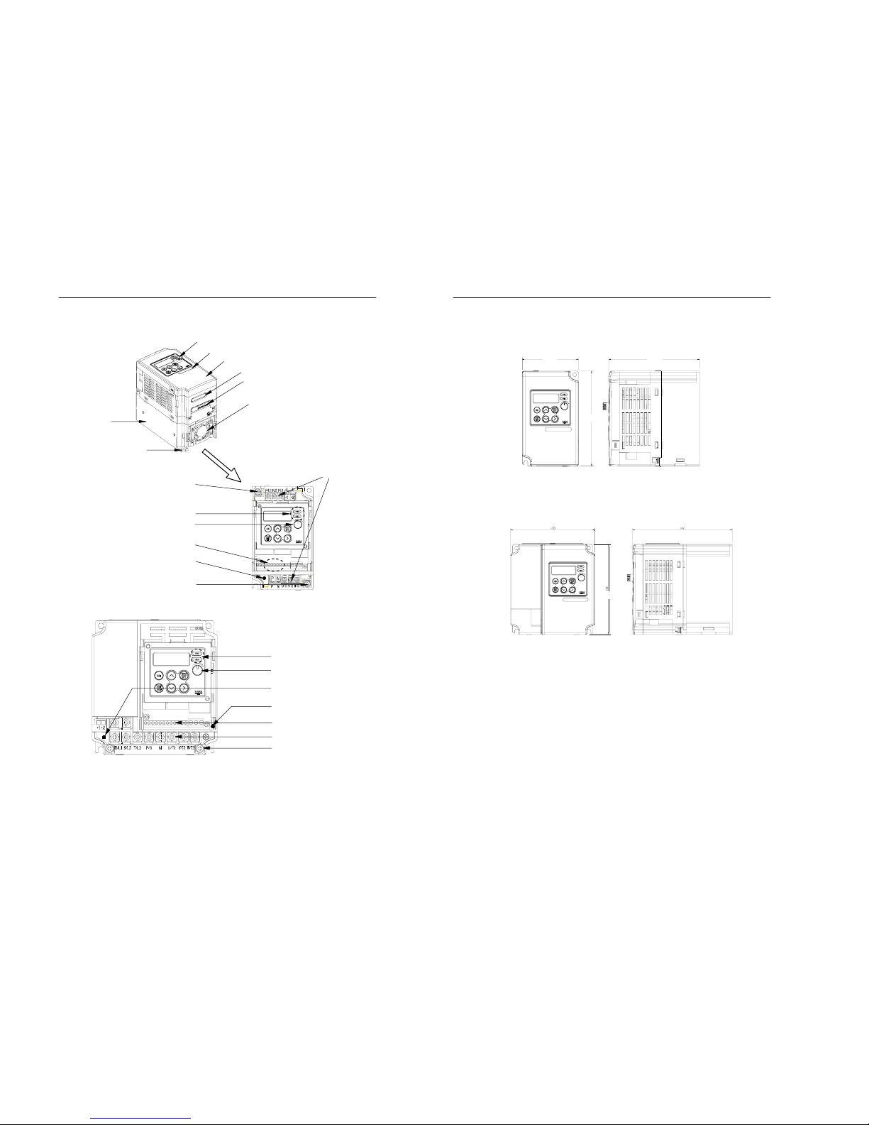
1.2 System diagram
Figure 1.1 System d i ag r am
Digital operator
Heatsink
Front cover
W
iring holes for main circuit
Cooling fan
Mounting hole
Sticker marked capacit
y
W
iring holes for control circuit
Ground terminal
Status indicating lamp
Main circuit terminal block
Control circuit terminal block
Digital volume
Ground terminal
Charge lamp
[1 phase 20P4S and 3 phase 20P4, 20P7]
Status indicating lamp
Digital volume
Control circuit terminal block
Main circuit terminal block
Ground terminal
Charge lamp (400V class)
Charge lamp (200V class)
[1 phase 20P7S, 21P5S, 22P2S and
3 phase 21P5, 22P2, 23P7, 40P4~43P7]
Opening the covers
1-6 MOSCON-E7 User’s Manual
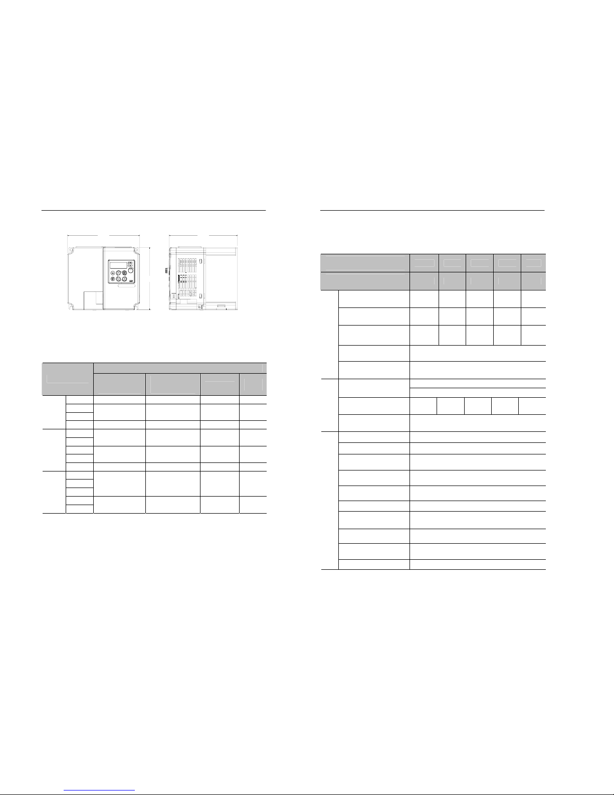
1.3 Dimensions
Figure 1.2 Dimensions of 1 phase 20P4 and 3 phase 20P4, 20P7
Figure 1.3 Dimensions of 1 phase 20P7, 21P5 and 3 phase 21P5,
22P2, 40P4~41P5
76 123
128
120 142
128
1. Overview 1-7
Figure 1.4 Dimension of 1 phase 22P2 and 3 phase 23P7, 42P2~43P7
Table 1.1 Dimensions of FARA MOSCON E-7
MOSCON-E7
Type
External
Dimension
(W×H ×D)
Installation
Dimension
W1×H1, Φ
Volume (㎣)
Weight
(㎏)
20P4S 76×128×123 66×118, M4 1,186,816 0.95
20P7S
21P5S
120×128×142 103×118, M4 2,150,400 1.6
200V
1phase
22P2S 150×128×142 134×118, M4 2,150,400 2.0
20P4
20P7
76×128×123 66×118, M4 1,186,816 0.95
21P5
22P2
120×128×142 103×118, M4 2,150,400 1.6
200V
3phase
23P7 150×128×142 134×118, M4 2,150,400 2.0
40P4
40P7
41P5
120×128×142 103×118, M4 2,150,400 1.6
42P2
400V
3phase
43P7
150×128×142 134×118, M4 2,688,000 2.0
150
142
128
1-8 MOSCON-E7 User’s Manual
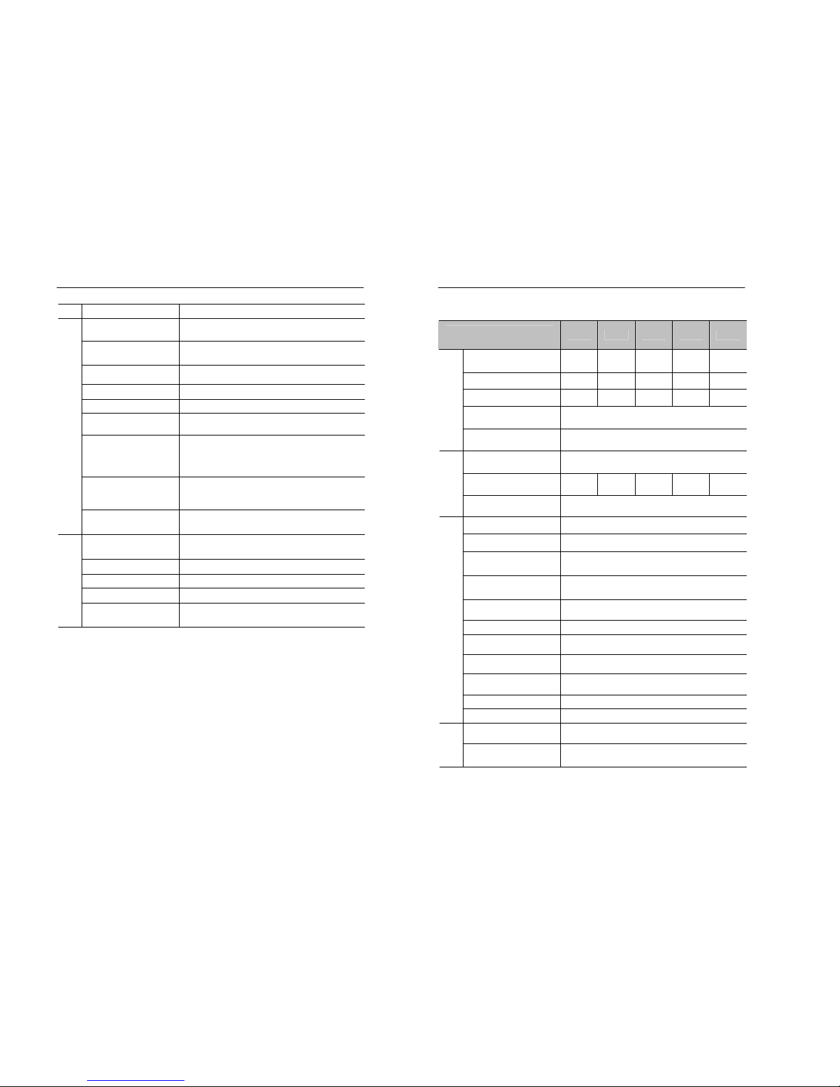
1.4 Specifications
Table 1.2 Specifications for 200V class
SI-E7
3 phase
20P4 20P7 21P5 22P2 23P7
SI-E7S
1 phase
20P4S 20P7S 21P5S 22P2S -
Max. Applicable
Motor Capacity[kW]
*1
0.4 0.7 1.5 2.2 3.7
Inverter Capacity[kVA]
(1 phase)
1.1
(1.1)
1.9
(1.7)
3.0
(2.7)
4.2
(3.7)
6.7
( - )
Rated Output Current[A]
(1 phase)
3.2
(3.2)
5.0
(4.6)
8.0
(7.2)
11.0
(9.6)
17.5
( - )
Rated Output Voltage[V]
3 phase, 200~230Vac
(Proportional to input voltage)
Output
Max. Output Frequency
[Hz]
600Hz
3Phase, 200~230Vac, 50/60Hz
Input Voltage and
Frequency
Single phase, 200~230Vac, 50/60Hz
Rated Input Current[A]
(1 phase)
3.9
(6.4)
6.4
(11.0)
11.0
(15.1)
15.1
(24.0)
24.0
( - )
Input
Allowable Fluctuation
Voltage: -15% ~ +10%,
Frequency: ±5%
Control Method Space vector PWM, VVVF method
Frequency Control Range 0.01 ~ 600Hz*2
Frequency Control
Accuracy
Digital :±0.01% (-10 ~ 50℃)*2
Analog :±0.5% (25℃±10℃)
Frequency Setting
Resolution
Digital (operator) : 0.01Hz
Analog:0.06/60Hz(1/1,024:10-bit)
Output Frequency
Resolution
0.01Hz
Overload Capacity 150% of rated current for 1min
Frequency Setting Signal
DC0~10V (Input impedence:20 ㏀)
DC4~20mA (
Input impedence
:250Ω)
Accel/Decel Time
0.1~3000.0sec (uni t of 0.1sec setting )
2 sets available
Continuous Regenerative
Torque
20% of rated torque
Control Characteristic
V/f Pattern 15 of fixed pattern and 1 of optional pattern
1. Overview 1-9
Starting Torque 150%/3Hz
Motor Overload
Motor stops in 1 minute at approx. 150% of
motor rated current.
Instantaneous
Overcurrent
Motor stops immediately at 200% of inverter
rated current.
Inverter Overload
Motor coasts to stop in 1 minute at approx.
150% of inverter rated curren t.
Overvoltage Motor stops at 410V or higher.
Undervoltage Motor stops at 190V or lower.
Cooling Fin
Overheat
Motor stops if the temper ature of the co oling
fin is higher than approximately 90℃.
Momentary Power Loss
Motor stops if power loss is 15ms or longer,
by selecting the momentary power loss mode,
operation can be continued if power is
restored within 500ms.
Stall Prevention
Automatic setting during acceleration,
deceleration, and constant speed operation
(Individual setting is possible).
Protective Functions
Power Charge
Indication
LED is ON until the DC bus voltage be comes
50V or less.
Location
Indoor
(Free from corrosive gas, dust, or oil)
Ambient Temperature -10 ~ 40℃
Humidity 90% RH or less
Storage Temperature -20 ~ 60℃*3
Environmental
condition
Vibration
Normally 0.2G or less, less than 20Hz, 1G
max.
*1. The maximum applicable motor capacity is for a standard 4-pole
motor. When selecting the motor and inverter, make sure that the
Inverter’s rated current is applicable for the motor’s rated current.
*2. Tuning may be required.
*3.
The storage temperature refers to the temperature during the
transportation for a short period of time.
1-10 MOSCON-E7 User’s Manual
Table 1.3 Specifications for 400V class
SI- E7
3 phase
40P4 40P7 41P5 42P2 43P7
Max. Applicable
Motor Capacity[kW]
*1
0.4 0.7 1.5 2.2 3.7
Inverter Capacity[kVA] 1.4 2.6 3.7 4.2 6.5
Rated Output Current[A] 1.8 3.4 4.8 5.5 8.6
Rated Output Voltage[V]
3phase, 380~460Vac
(Proportional to input voltage)
Output
Max. Output Frequency
[Hz]
600Hz
Input Voltage
and Frequency
3 Phase, 380~460Vac, 50/60Hz
Rated Input Current[A] 2.4 4.7 7.0 8.1 12 .0
Input
Allowable Fluctuation
Voltage: -15% ~ +10%,
Frequency: ±5%
Control Method Space vector PWM, VVVF method
Frequency Control Range 0.01 ~ 600Hz*2
Frequency Accuracy
Digital : ±0.01% (-10 ~ 50℃)
*2
Analog : ±0.5% (25℃±10℃)
Frequency Setting
Resolution
Digital (operator): 0.01Hz
Analog: 0.06/60Hz (1/1,024:10-bit)
Output Frequency
Resolution
0.01Hz
Overload Capacity 150% of rated current for 1min
Frequency Setting Signal
DC0~10V(
Input impedence
:20 ㏀)
DC4~20mA(
Input impedence
:250Ω)
Accel/Decel Time
0.1~3000.0sec (uni t of 0.1sec setting)
Includes 2-set each.
Continuous Regenerative
Torque
20% of rated torque
V/f Pattern 15 of fixed pattern and 1 of optional pattern
Control Characteristics
Starting Torque 150%/3Hz
Motor Overload
Protection
Motor stops in 1 minute at approx. 150% of
motor rated current.
Protective
Function
Instantaneous
Overcurrent
Motor stops immediately at 200% of inverter
rated current.
1. Overview 1-11
Inverter Overload
Motor coasts to stop in 1 minute at approx.
150% of inverter rated curren t.
Overvoltage Motor stops at 820V or higher.
Undervoltage Motor stops at 380V or lower.
Cooling Fin
Overheat
Motor stops if the temperature of the
cooling fin is h igher than 90℃.
Momentary Power Loss
Motor stops if power loss is 15ms or longer,
by selecting the momentary power loss
mode, operation can be continued if power
is restored within 500ms.
Stall Prevention
Automatic setting during acceleration,
deceleration, and constant speed operation
(individual setting is possible).
Power Charge
Indication
LED is ON until the DC bu s voltage
becomes 50V or less.
Location
Indoor
(Free from corrosive gas, dust, or oil)
Ambient Temperature -10 ~ 40℃
Humidity 90% RH or less
Storage Temperature -20 ~ 60℃*3
Environmental
condition
Vibration
Normally 0.2G or less, less than 20Hz, 1G
max.
*1. The maximum applicable motor capacity is for a standard 4-pole
motor. When selecting the motor and inverter, make sure that the
inverter’s rated current is applicable fro the motor’s rated current.
*2. Tuning may be required.
*3. The storage temperature refers to the temperature during the
transportation for a short period of time.
1-12 MOSCON-E7 User’s Manual
1.5 Short circuit rations
Suitable for use in a circuit capable of delivering not more than 5kA rms
symmetrical amperes.
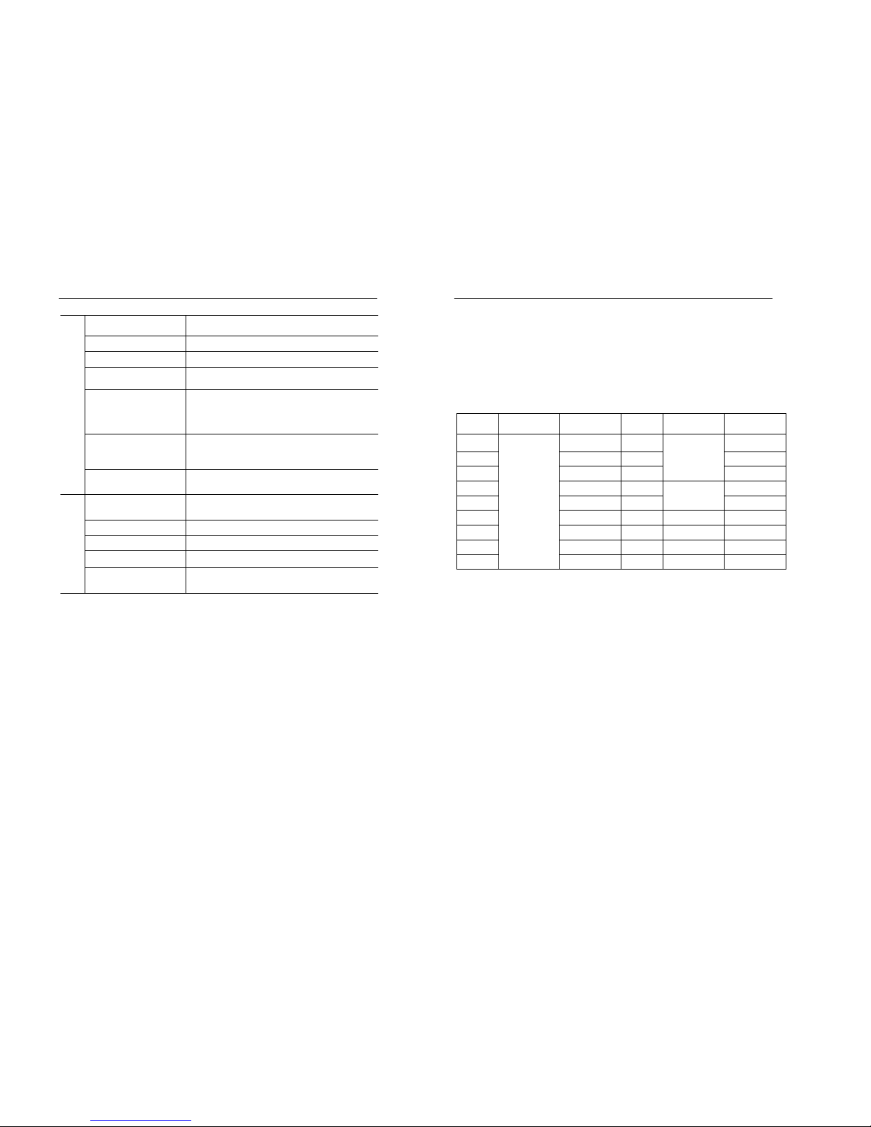
1.6 Fuse
The fuse used on the input side should be any of the UL Class K5 fuses having
The ratings as listed below.
Model
Rated
Voltage(V)
Rated
Current(A)
Model Rated
Voltage(V)
Rated
Current(A)
20P4 10 40P4 16
20P7 10 40P7 16
21P5 20 41P5
500
16
22P2 20 42P2 20
23P7 30 43P7
600
20
20P4S 20
20P7S 20
21P5S 20
22P2S
250
30

2. Installation 2-1
2. Installation
Nameplate information and installation site are described in this
chapter.
2.1 Receiving............................................................... ....................2-3
2.2 Nameplate Information .......................................................... 2-4
2.3 Installation.................................................................................2-5
2-2 MOSCON-E7 User’s Manual
2. Installation 2-3
2.1 Receiving
Confirm the following upon delivery of the Moscon-E7:
• Verify the model number to check if the correct item has been
delivered.
• Check if any physical damage has occurred during shipping.
If there is any damage or missing part, call the place where you
purchased the product or sales office for service immediately.
• Don’t install the inverter that there is any damage or missing part.
It may be cause injury.
CAUTION
!
2-4 MOSCON-E7 User’s Manual
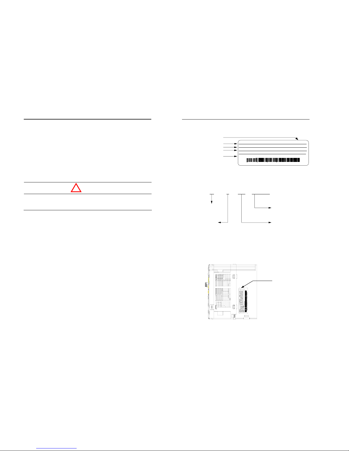
2.2 Nameplate information
Figure 2.1 Example of nameplate
Inverter model number
Name plate location
Max. motor capacity
0P4:0.4kW
0P7:0.7kW
1P5:1.5kW
2P2:2.2kW
3P7:3.7kW
Samsung inverter
SI 4 3P7 E7/EXP
Voltage cl ass
2 : 200V class
4 : 400V class
E7 series
E7/EXP : 3 phase
E7/EXS : 1 phase
MODEL : SI43P7E7/EXP PRG:V019
Input Voltage : A C3PH 380-460V 50/60Hz 12.0A
Output Power: AC3PH 0-460V 6.5kVA 8.6A 0.01-600Hz
IP20 INSTALLATION CATEGORY Ⅱ MASS : 2.0kg
SER. NO : 2Q15A20002
SAMSUNG ELECTRONICS CO., LTD. MADE IN KOREA
Program version
Model number
Input specifications
Output specifications
Serial number
Name plate
(Attachment an the right side)

2. Installation 2-5
2.3 Installation
2.3.1 Precautions for delivery and installation
• Do not inspect components unless inside “Charge” lamp is off.
It may cause an electric shock.
• Do not remove the operator from the main body.
It may cause an electric shock.
• When using the digital operator away from the main body, use the
separated operator (E7OPTR-S).
• Be careful not to be damaged the inverter in delivering.
• Do not carry the inverter by holding the plastic parts, but hold the
heat sink.
Otherwise, the heat sink may fall and cause injury.
• Use nonflammable materials such as metal for the part where the
inverter is installed.
• When installing several inverters in a single enclosed space, install a
cooling fan to keep the ambient temperature below 45℃.
• Cover the inverter during installation to protect it from metal chip
coming from drilling.
DANGER
!
CAUTION
!
2-6 MOSCON-E7 User’s Manual
2.3.2 Installation site
Free from direct
sunlight
Free from harmful
gases and liquids
Free from oil mist and
dust
Free from chlorides
F
ree from rain and
wind, water
(In case of enclosed
wall mount t
yp
e)
Free from dust
(In case of enclosed
wall mount type)
Without excessive
vibration
Low ambient
temperature
Ambient temperature of
– 10℃~40℃
Without
any magnetic
noises
(e.g. Free from a welding
machine or power supply)
Free from radioactive
material
Free from combustible
material
2. Installation 2-7
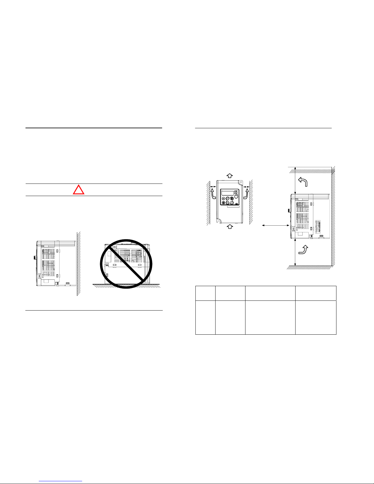
2.3.3 Controlling the ambient temperature
To maintain the optimum condition, the inverter should be installed at
the ambient temperature of –10℃~40℃. If installed in a closed
environment (e.g. enclosed panel), install a cooling fan or air conditioner
to avoid any extreme temperature increases and to maintain the internal
air temperature within the range.
• If installed in a closed environment (e.g. enclosed panel), we
strongly recommend the inverter to be installed on a vertical space.
If it is installed on a horizontal space, its internal temperature may
increase excessively and thus, reducing its durability.
CAUTION
!
Vertical mounting Herizontal mounting
2-8 MOSCON-E7 User’s Manual
2.3.4 Installation space
Install the inverter on a vertical surface to enhance the cooling effect.
When installing the inverter, always leave enough space around it to
provide normal heat dissipation.
Figure 2.2 Installation space
Table 2.1 Cabinet Size
Inverter
Cabinet
(enclosure)
Size(Unit:mm)
Vent Hole Area Cooling Fan
23P7 270x328x222
· 55% of both the side
of the cabinet
· width of each slit :
3.2mm
· To be provided on each
of the upper side areas
Installed at the
enclosure top to suck
air from inside the
enclosure to the
outside.
(Fan air flow : 2x0.59
m
3
/min or more
100mm or more
Inlet Temp.
-10~+40℃
30mm or more
Airflow
30mm or more
100mm or more
80mm or more

3.Wiring 3-1
3. Wiring
Wiring specifications, terminals, main circuit terminal
connection, peripheral device connection and
precautions in wiring are described in this chapter.
3.1 Connection diagram ................................................................ 3-4
3.2 Terminal block configuration ................................................. 3-6
3.3 Main circuit terminal functions.............................................. 3-7
3.4 Control circuit terminal functions ......................................... 3-8
3.5 Connections to peripheral devices .........................................3-9
3.6 Wiring the main circuits........................................................ 3-10
3.7 Precautions when wiring....................................................... 3-18
3.8 Grounding...............................................................................3-20
3.9 Cable specification ................................................................. 3-21
3.10 Wiring check......................................................................... 3-22
3-2 MOSCON-E7 User’s Manual
3.Wiring 3-3
• Always turn OFF the input power supply before wiring.
Otherwise, an electric shock or fire may occur.
• Wiring must be performed by a qualified personnel.
• Always check if the volts on the main circuit and control circuit
terminals are properly tightened.
• Be sure to ground the ground terminal.
Otherwise, an electric shock or fire may occur.
• Turn ON the inverter only after completely assembling the covers.
Do not detach the cover when the power is ON.
Otherwise, an electric shock or fire may occur.
• Ground the ground terminal (200V & 400V class: ground to 100
or less). Otherwise, an electric shock or fire may occur.
• Tighten all terminal screws of the main circuit and the control
circuit.
• Check if the voltage of the inverter rated voltage satisfies with the
AC power su pply volta ge.
Otherwise, it may cause fire or injury.
• Do not perform withstand voltage test on the inverter. It may
damage the semi-conductor element.
• When wiring other devices, read their manuals carefully. Samsung
is not responsible for any accident resulting from user’s carelessness.
If not, it may cause injury or fire.
• Do not connect AC power to output terminal U, V and W.
Otherwise, it may damage the inverter.
• Do not connect electromagnetic switches or contactors to the
output circuits.
DANGER
!
CAUTION
!
3-4 MOSCON-E7 User’s Manual
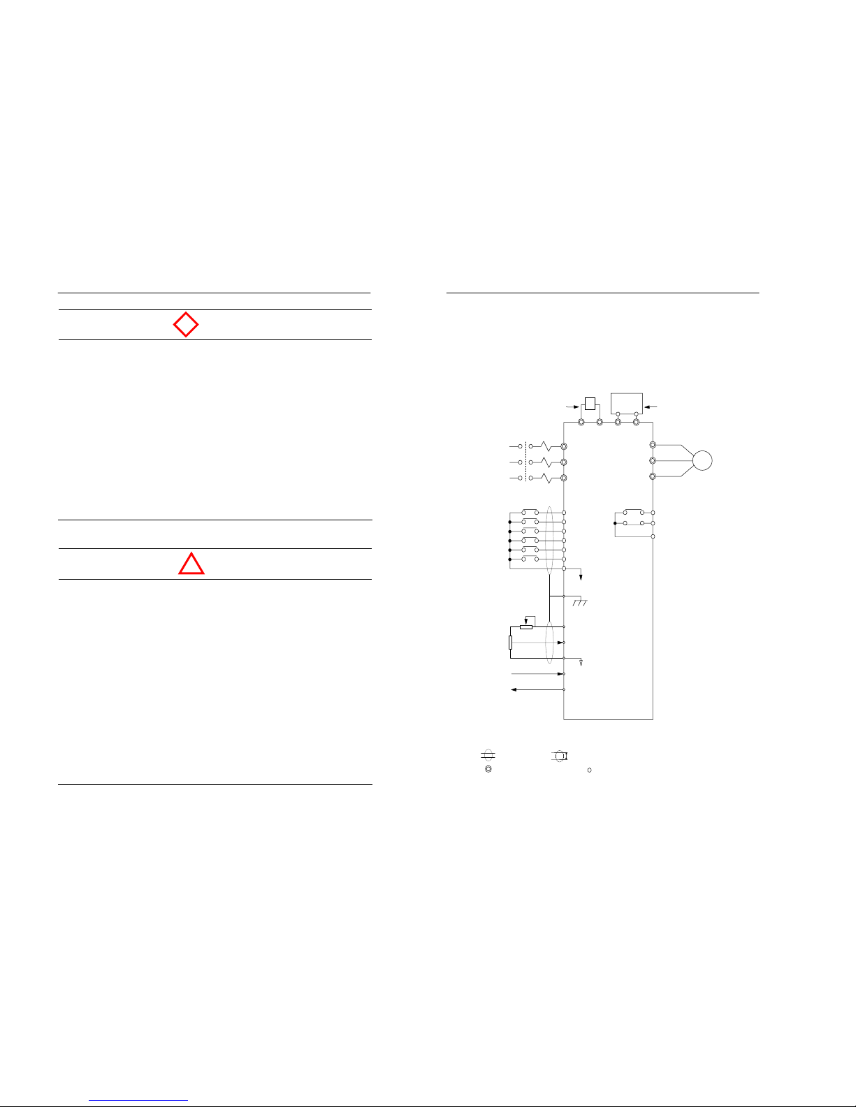
3.1 Connection diagram
The connection diagram of the Moscon-E7 is shown below.
When using the digital operator, the motor can be operated by wiring
only the main circuits.
Figure 3.1 Connection diagram (200V class)
Note 1) : Shield wire, : Twisted pair shield wire.
2) : Main circuit terminal, : Control circuit terminal.
3) Max. current value for +12V voltage of the control circuit terminal No.8 is 20㎃.
External Braking Unit (optional)
There is no built-in internal
braking unit for the 200V
class. Thus, external bra king
unit should be used.
External DC reactor to
improve power factor.
(op
tional
)
+1
Input power
MCCB
E
8
9
12
10
11
Multi-function
contact input
Multi-function
contact output
DC 30V 1A max
AC 250V 1A max
(basic setting : fault)
1k
2k
Power for speed command
(+12V 20mA)
Sequence Command
Ground
S
peed comman
d
(0~10V 20k)
Analogcommand
S
peed comman
d
(4~20mA 250)
Analog
monitor output
(0~10V)
+2
NP/B
Motor
R/L1
S/L2
T/L3
U/T1
V/T2
W/T3
Forward run/stop
Reverse r un/stop
External fault
Fault r eset
Multi-step command1
Jogg ing
1
2
3
4
A1
B1
C1
7
6
5
M
p
3.Wiring 3-5
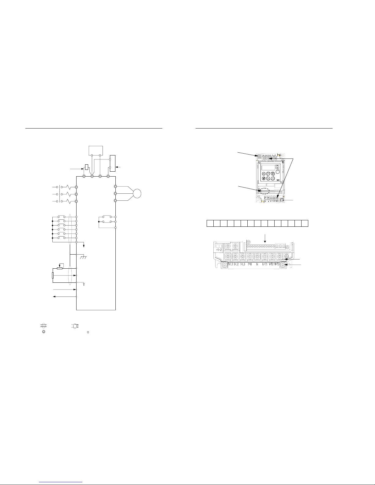
Figure 3.2 Connection diagram (400V class)
Note 1) : Shield wire, : Twisted pair shield wire.
2) : Main circuit terminal, : Control circuit ter minal.
3) Max. current value for +12V voltage of the control circuit terminal No.8 is 20㎃.
+1
MCCB
+2
N P/B
Built-in braking unit is available
for the 400V class. Thus, the
external braking resistor can be
installed as an option. External
braking unit is an option
External DC reactor to
improve power factor.
(optional)
Input power
E
8
9
12
10
11
Multi-function
contact input
Multi-function
contact output
DC 30V 1A max
AC 250V 1A max
(
basic settin
g
: fault
)
1k
2k
Power for speed command
(+12V 20mA)
Sequence Command
Ground
S
peed command
(0~10V 20k)
Analog command
S
peed command
(4~20mA 250)
Analog
monitor output
(0~10V)
Motor
R/L1
S/L2
T/L3
U/T1
V/T2
W/T3
Forwa rd run/ stop
Reverse r un/stop
External fault
Fault r eset
Multi-step command1
Jogg ing
1
2
3
4
A1
B1
C1
7
6
5
Braking resistor
Unit
(optional)
Braking Unit or Auxiliary Capacitor
(optional)
M
p
3-6 MOSCON-E7 User’s Manual
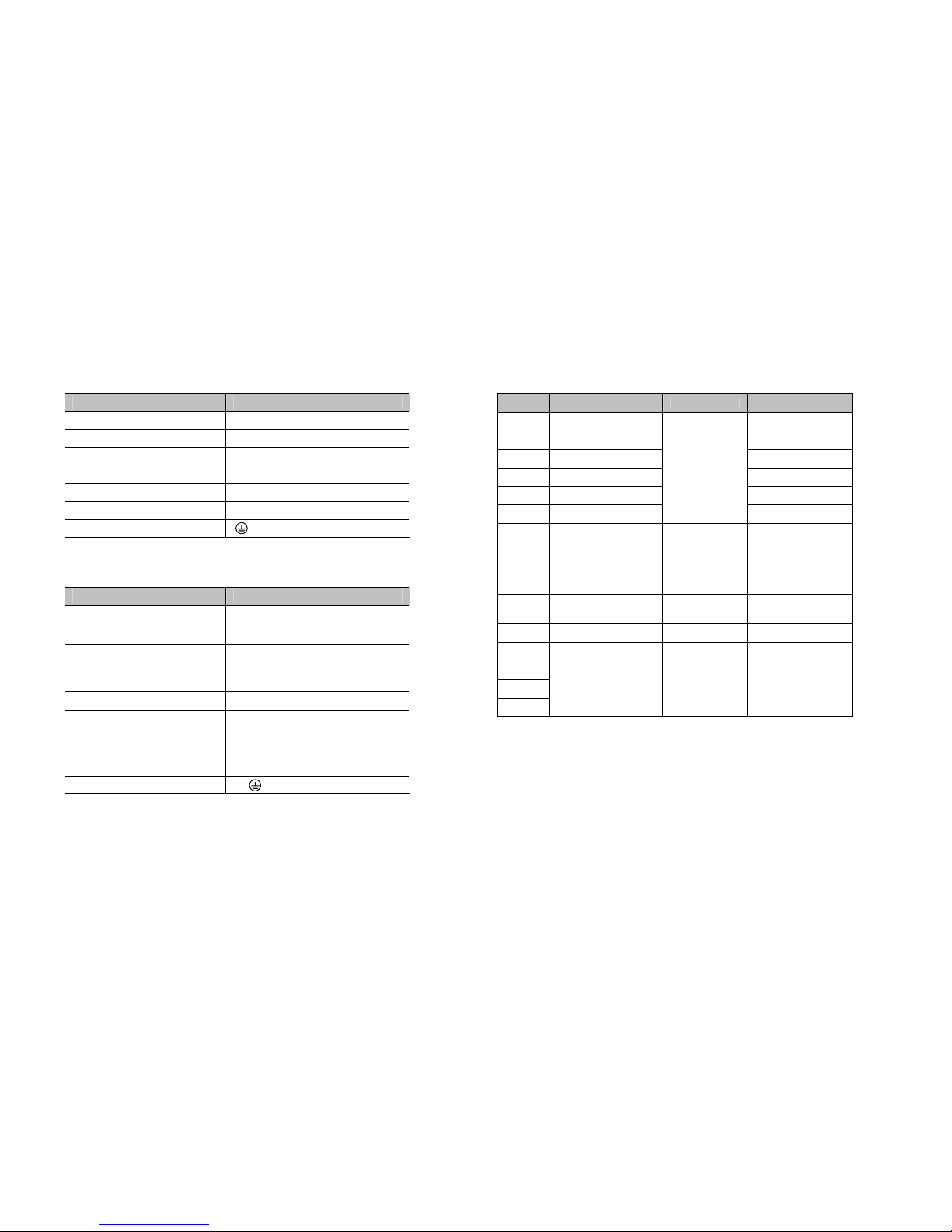
3.2 Terminal block configuration
1 2 3 4 5 6 7 8 9 10 11 12 A1 B1 C1
[21P5 – 23P7, 40P4 – 43P7]
Figure 3.3 Terminal configuration
Ground terminal
Control circuit
terminal block
Ground terminal
Main circuit terminal
block
[20P4, 20P7]
Control circuit ter minal
Main circuit terminal
Ground terminal
[20P4, 20P7]
3.Wiring 3-7
3.3 Main circuit terminal functions
Table 3.1 200V class main circuit terminal functions
Purpose Symbol
Main circuit power input R/L1, S/L2, T/L3
Inverter outputs U/T1, V/T2, W/T3
DC power input +1, N
DC reactor connection +1, +2 (Remove short-bar)*
Braking unit connection P/B, N (No internal braking unit)
Auxiliary capacitor (+): P/B (-):N
Ground
*Short-bar must be removed when connecting the DC reactor.
Table 3.2 400V class main circuit terminal functions
Purpose Terminal Symbol
Main circuit power input R/L1, S/L2, T/L3
Inverter output U/T1, V/T2, W/T3
DC power input
+2, N (Additional circuit is needed to
prevent the damage caused by inrush
current.)
DC reactor connection +1, +2(Remove short-bar)*
Braking resistor unit
+2, P/B (used for the internal braking
unit)
Braking unit +2, N
Auxiliary capacitor (+) : +2 (-) : N
Ground
*Short-bar must be removed when connecting the DC reactor.
3-8 MOSCON-E7 User’s Manual
3.4 Control circuit terminal f unctions
Table 3.3 Control ci rc u it t erminal block
Ter minal Function Signal level Default setting
1 Forward run/stop command -
2 Reverse run/stop command -
3 Multi-function input 1 External fault
4 Multi-function input 2 Fault reset
5 Multi-function input 3 Multi-step speed1 command
6 Multi-function input 4
Photo-Coupler input
+24V, 10mA
Jogg ing comma nd
7
Sequence control input
common
+24V Ground Sequence 0V
8 Power for freq. command +12V(Max 20mA) -
9
Voltage command for output
frequency
DC 0~+10V(25Ω) -
10
Current command for
output frequency
4~20mA(250Ω) -
11 Analog monitor output 0V 12 Common for control DC 0 ~ +10V (Output frequency)
A1
B1
C1
Multi-function output
Contact :
AC 250V, 1A or below
DC 30V, 1A or below
Fault occu rred
Note) Be attentive to below mention when changing output frequency in using the
external frequency command terminal.
- Voltage command input terminal is set only in factory setting.
- Change setting value of parameter H2.01 from 0 to 1 in using the current
command input terminal.
- In setting the function of contact input, H0.02~H0.05, parameter H2.01
is regardless if voltage current command transfer(14) is set.
3.Wiring 3-9
3.5 Connections to peripheral devices
Examples of connections between the Moscon-E7 and peripheral
devices are shown in the figure below
.
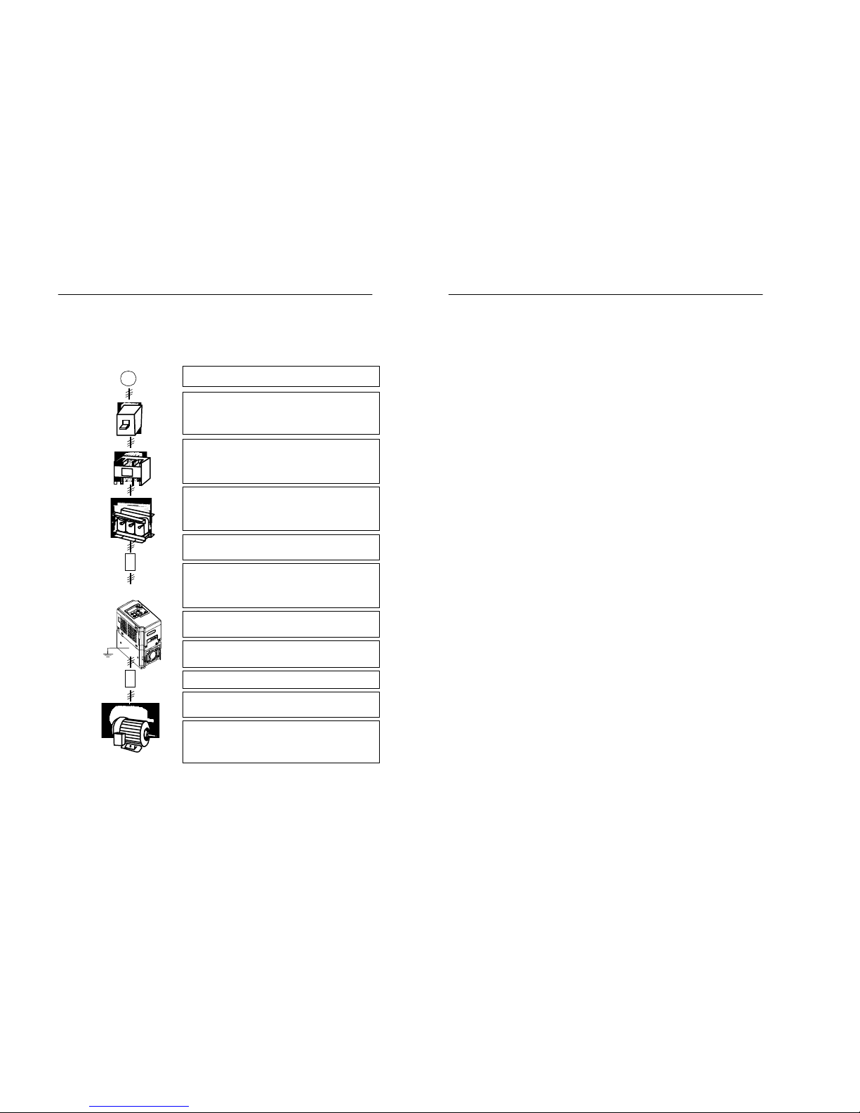
Figure 3.4 Peripheral devices
Power supply
Follow the specification on power supply.
Molded-case circuit breaker or leakage current
circuit breaker
Large inrush current flows when power is supplied thus,
use appropriate breaker, which is tolerant to high
frequency.
Magnetic contactor
Installed to remote control the supply/block of the
power. Frequent start/stop of the inverter through this
device reduces durability of the inverter. Install the
surge absorber on the coil.
AC/DC reactor for power factor improvement
AC/DC reactor is required when improving the power
factor or when the inverter is connected to a largecapacity power transformer whose capacity is 600kVA or
more. If not, invert may be damaged.
Input noise filter
Install it close to the inverter to reduce the noise from the
wire.
Input wiring
Inappropriate wiring damages the inverter. Do not
connect input power R, S, and T to output U/T1, V/T2,
and W/T3. Keep enough distance between the control
signal line and main circuit to prevent the effect of noise.
Installation area
Install in a place free from gas and dust. Maintain the
ambient temperature within the specified range.
Output noise filter
Install the output noise filter close to the inverter to
reduce the noise from output wire of the inverter.
Motor
Follow the specification when running the motor.
Grounding
Ground the inverter and motor to prevent any electric
shock.
Wiring between the inverter and motor
Keep the wire between the inverter and motor short.
If not, it may decrease the carrier frequency.
Leakage current from the cable affects the inverter and
other peripheral devices.
~
접 지
Power supply
Molded-case
circuit breaker or
leakage current
circuit breaker
Magnetic contactor
AC/DC reactor
for power factor
im
p
rovement
Input noise filter
MOSCON-E7
Ground
Output noise filter
Motor
Ground
3-10 MOSCON-E7 Us er’s Manual
3.6 Wiring the main circuits
3.6.1 Wiring on the input side of main circuit
3.6.1.1 Installing a molded-case circuit breaker
• Always connect the input power terminals (R/L1, S/L2 and T/L3) via
an appropriate MCCB.
•
Large inrush current flows when power-up, thus, use appropriate
breaker. Use the one that is tolerant to high frequency.
• MCCB with a capacity of 1.5 to 2 times greater than the rated current
of the inverter should be used.
• When one MCCB is used for more than one device (e.g. inverter), the
sequence must be set up so that the power supply is turned off by a
fault output.
3.6.1.2 Installing a magn etic contactor (MC)
• The inverter is able to use without the magnetic contactor of power
supply side.
• In case of installing the magnetic contactor to input power supply in
order to prevent an accident occurred by the automatic restart
operation after the recovery from a power interruption, frequent
start/stop of the inverter through this device reduces durability of the
inverter.
• When the digital operator is used, unless the inverter operation mode is
set to the automatic start operation, it cannot be automatically started
after the recovery rom a power interruption.
• Install the surge absorber on the coil.
3.Wiring 3-11
Table 3.4 MCCB and magnetic contactor
MCCB
Model
Capacity
(kVA)
Rated
Output
Current(A)
AF AT
Magnetic
Contactor
Rated Current(A)
20P4 1.1 3.2 30A 5A 10A
20P7 1.9 5.0 30A 10A 10A
21P5 3.0 8.0 30A 20A 10A
22P2 4.2 11.0 30A 20A 20A
23P7 6.7 17.5 30A 30A 20A
40P4 1.4 1.8 30A 5A 10A
40P7 2.6 3.4 30A 5A 10A
41P5 3.7 4.8 30A 10A 10A
42P2 4.2 5.5 30A 10A 10A
43P7 6.5 8.6 30A 20A 10A
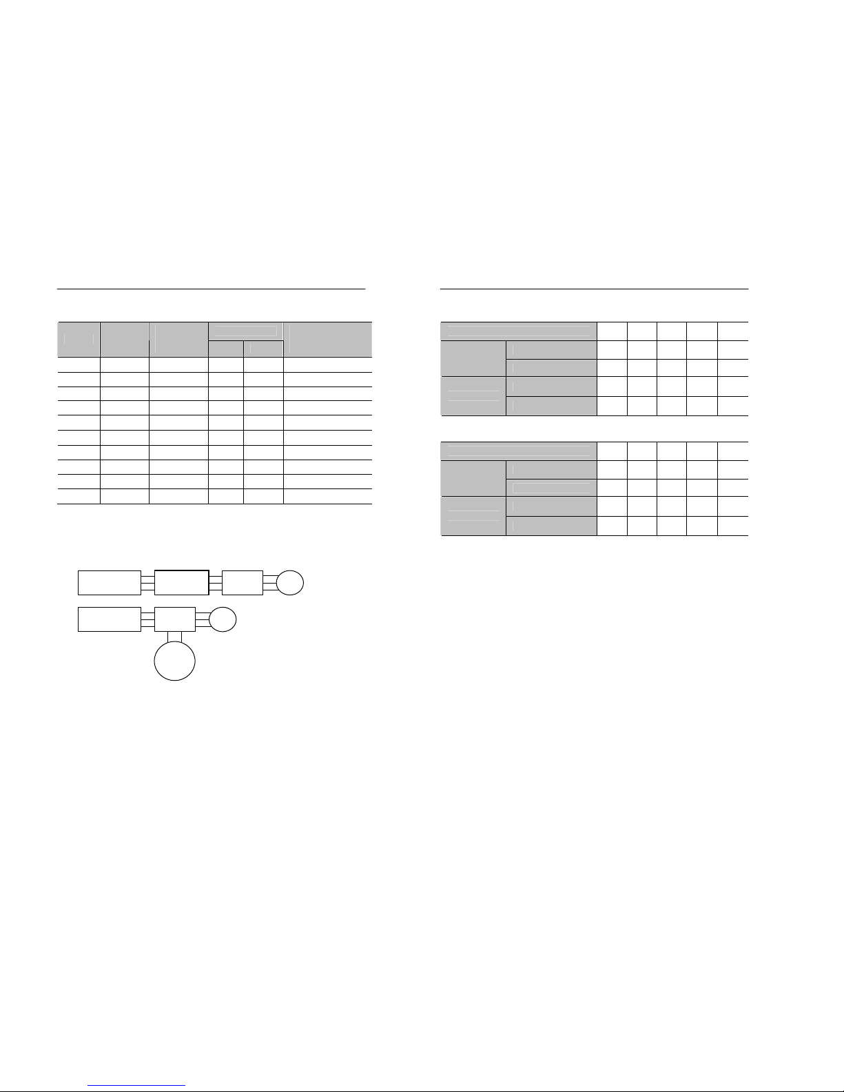
3.6.1.3 Installing an AC reactor/DC reactor
• Two options are available when the inverter is connected to a largecapacity power transformer whose capacity is 600kVA or higher:
Figure 3.5 Reactor installation
• If not, inverter may be damaged due to an excessive peak current flow
through the input power circuit.
• AC reactor/DC reactor also can be used to improve the power factor
on input power supply side.
Transformeter
AC Reactor
Inverter
Transformeter
M
DC
Reactor
M
Inverter
3-12 MOSCON-E7 Us er’s Manual
Table 3.5 DC Reactor
Inverter capacity(kW) 0.4 0.7 1.5 2.2 3.7
Current[A] 5.4 5.4 18 18 18
200V Class
Inductance[mH] 8 8 3 3 3
Current[A] 3.2 3.2 5.7 5.7 12
400V Class
Inductance[mH] 28 28 11 11 6.3
Table 3.6 AC Reactor
Inverter capacity(kW) 0.4 0.7 1.5 2.2 3.7
Current[A] 2.5 5 10 15 20
200V Class
Inductance[mH] 4.1 2.1 1.1 0.71 0.53
Current[A] 1.3 2.5 5 7.5 10
400V Class
Inductance[mH] 28 8.4 4.2 3.6 2.2
3.6.1.4 Connecting input power supply
• Input power supply can be connected to any terminal R/L1, S/L2, or
T/L3 on the terminal block; the phase sequences of input power
supply are irrelevant.
3.6.1.5 Installing a surge absorber
• A surge absorber must be used for inductive loads near the FARA
MOSCON-E7. Otherwise, it may damage the devices or cause
malfunctioning.
• These inductive loads includes:
- MC,
- Electromagnetic relay,
- Solenoid valves and solenoids,
- MCCB

3.Wiring 3-13
Table 3.7 Application of the surge absorber
Description Model Specification
Large Capacity Coil
except Relay
DCR2-50A 22E AC250V 0.5u ㎌ 200Ω
200
~230V
Control Relay DCR2-10A 25C AC250V 0.1 ㎌ 100Ω
380~460V Devices DCR2-50D 100B DC 1000V 0.5 ㎌ 220Ω
Note) The above surge absorbers are the product of MARCON. Use the recommend product or
equivalents.
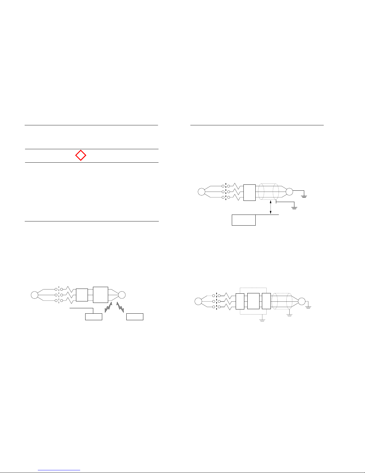
3.6.1.6 Installing a noise filter on power supply side
• Install the noise filter in order to eliminate noise transmitted from the
power line to the inverter.
(a) Wiring example 1 (Correct)
(b) Wiring example 2
IM
◠
◠
◠
~
MCCB
◠
◠
MCCB
Control
circuit
E7
※Use the noise filter
designed specifically
for the inverter
Power
Noise filter
IM
◠
◠
◠
~
MCCB
E7
Power
Noise filter
※Noise filter is not
necessary if the inverter
and power is used 1:1
3-14 MOSCON-E7 Us er’s Manual
(c) Wiring example 3
(d) Incorrect wiring example
Figure 3.6 Power supply noise filter installation
IM
◠
◠
◠
~
MCCB
◠
◠
MCCB
Control
circuit
E7
Power
General
noise
filter
IM
◠
◠
◠
General
noise
filter
~
MCCB
◠
◠
MCCB
Control
circuit
E7
※Usin
g
the general noise
filter is not effective.
Power
IM
◠
◠
◠
~
MCCB
◠
◠
MCCB
Control
circuit
E7
Power
※Connecting the insulating
transformer to power
supply of the control
circuit is same effective of
the noise filter.
3.Wiring 3-15
3.6.2 Wiring on the output side of main circuit
3.6.2.1
Precautions when wiring on the output side of main circuit
• Never connect a power supply to output terminals U/T1, V/T2,
and W/T3.
Otherwise, it may damage the internal circuits of the inverter.
• Never short or ground output terminals.
• The output wires should not have contact with the inverter heatsink.
• Do not connect a phase advancing capacitor or LC/RC noise
filter to an output circuit.
Otherwise, it may damage the inverter or cause a fire.
• Do not connect an electromagnetic switch or MC to an output
circuit.
Otherwise, it will actuate the overcurrent protection circuit of the
inverter.
3.6.2.2 Connecting the inverter and motor
• Connect output terminals U/T1, V/T2, and W/T3 to motor wires U, V,
and W respectively.
•
Check if the motor rotates in correct direction according to the
command. If not (motor rotating in reverse with the forward run
command), switch any of two output terminals to each other and
reconnected them.
3.6.2.3 Installing a noise filter on the output side
Install a noise filter to reduce radio noise and inductive noise.
Figure 3.7 Noise filter on the output side
IM
◠
◠
◠
Noise
filter
~
MCCB
E7
Power
Controller
AM radio
Radio noise
Inductive
noise
Signal
line
DANGER
!
Inductive noise: Noise generated on the signal line by electromagnetic
induction. It causes the controller to malfunction.
Radio noise: High-freq uency noise generated from the inverter and cables.
3-16 MOSCON-E7 Us er’s Manual
3.6.3 Dealing with inductive noises
• As mentioned previously, noise filter can be used to prevent the
inductive noise generated on the output side.
• As an option, cables can be routed through a grounded metal pipe to
prevent inductive noise.
• If the metal pipe and the signal line are at least 30cm apart, the
inductive noise can be considerably reduced
.
Figure 3.8 Dealing with inductive noise
3.6.4 Dealing with radio interference (RFI)
• Radio noise is generated from the inverter as well as the input/output
lines.
• The radio noise can be reduced by installing the noise filters on both
input and output sides, and also installing the inverter in an enclosed
and grounded steel box.
• Make the cable between the inverter and motor as short as possible.
Figure 3.9 Dealing with radio interference
IM
◠
◠
◠
~
MCCB
Power
Noise
filter
Noise
filter
E7
Metal pipe
◠
◠
◠
~
MCCB
Power
IM
Controller
30cm Min.
Signal line
Metal pipe
E7
 Loading...