

Samsung MO15E Series Service Manual
TFT-LCD MONITOR
MO15E*
Manual
SERVICE
TFT-LCD MONITOR CONTENTS
1. Precautions
2. Product Specifications
3. Disassembly & Reassembly
4. Troubleshooting
5. Exploded View & Parts List
6. Electrical Parts List
7. Block Diagram
8. Wiring Diagram
9. Schematic Diagrams
10. Panel Description
CONFIDENTIAL
1-1-1 Warnings
1. For continued safety, do not attempt to modify the
circuit board.
2. Disconnect the AC power and DC Power Jack
before servicing.
3. When the chassis is operating, semiconductor
heatsinks are potential shock hazards.
1-1-2 Servicing the LCD Monitor
1. When servicing the LCD Monitor, remove the static
charge by connecting a 10k ohm resistor in series
with an insulated wire (such as a test probe)
between the chassis and the anode lead.
(Disconnect the AC line cord from the AC outlet.)
2. It is essential that service technicians have an
accurate voltage meter available at all times. Check
the calibration of this meter periodically.
1-1-3 Fire and Shock Hazard
Before returning the monitor to the user, perform the
following safety checks:
1. Inspect each lead dress to make certain that the
leads are not pinched or that hardware is not
lodged between the chassis and other metal parts in
the monitor.
2. Inspect all protective devices such as nonmetallic
control knobs, insulating materials, cabinet backs,
adjustment and compartment covers or shields,
isolation resistor-capacitor networks, mechanical
insulators, etc.
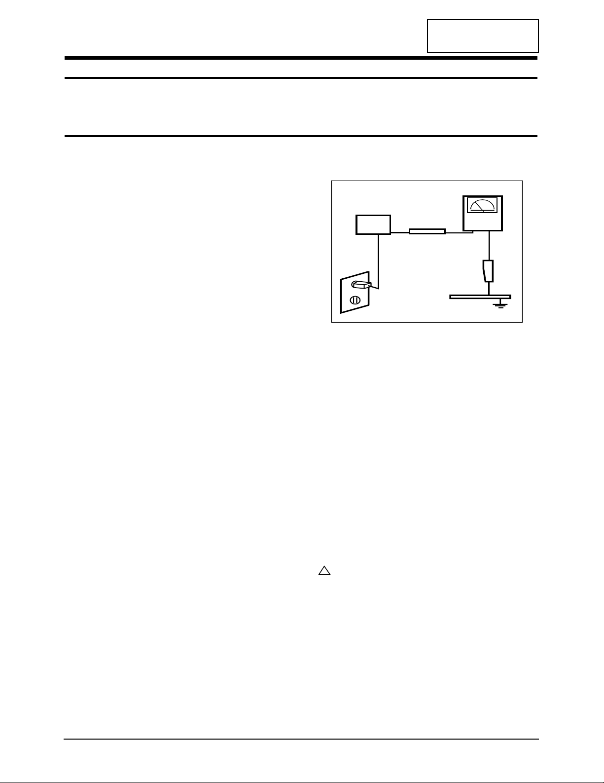
3. Leakage Current Hot Check (Figure 1-1):
WARNING: Do not use an isolation transformer during
this test.
Use a leakage current tester or a metering system
that complies with American National Standards
Institute (ANSI C101.1, Leakage Current for
Appliances), and Underwriters Laboratories (UL
Publication UL1410, 59.7).
Figure 1-1. Leakage Current Test Circuit
4. With the unit completely reassembled, plug the AC
line cord directly into a 120V AC outlet. With the
unit’s AC switch first in the ON position and then
OFF, measure the current between a known earth
ground (metal water pipe, conduit, etc.) and all
exposed metal parts, including: metal cabinets,
screwheads and control shafts. The current
measured should not exceed 0.5 milliamp. Reverse
the power-plug prongs in the AC outlet and repeat
the test.
1-1-4 Product Safety Notices
Some electrical and mechanical parts have special
safety-related characteristics which are often not
evident from visual inspection. The protection they give
may not be obtained by replacing them with
components rated for higher voltage, wattage, etc. Parts
that have special safety characteristics are identified by
on schematics and parts lists. A substitute
replacement that does not have the same safety
characteristics as the recommended replacement part
might create shock, fire and / or other hazards. Product
safety is under review continuously and new
instructions are issued whenever appropriate.
MO15E* 1-1
CONFIDENTIAL
1 Precautions
Follow these safety, servicing and ESD precautions to prevent damage and to protect against potential hazards such as
electrical shock.
1-1 Safety Precautions
DEVICE
UNDER
TEST
TEST ALL
EXPOSED METAL
SURFACES
(READING SHOULD
NOT BE ABOVE 0.5mA)
LEAKAGE
CURRENT
TESTER
2-WIRE CORD
ALSO TEST WITH
PLUG REVERSED
(USING AC ADAPTER
PLUG AS REQUIRED)
EARTH
GROUND
!
CONFIDENTIAL
2 Product Specifications
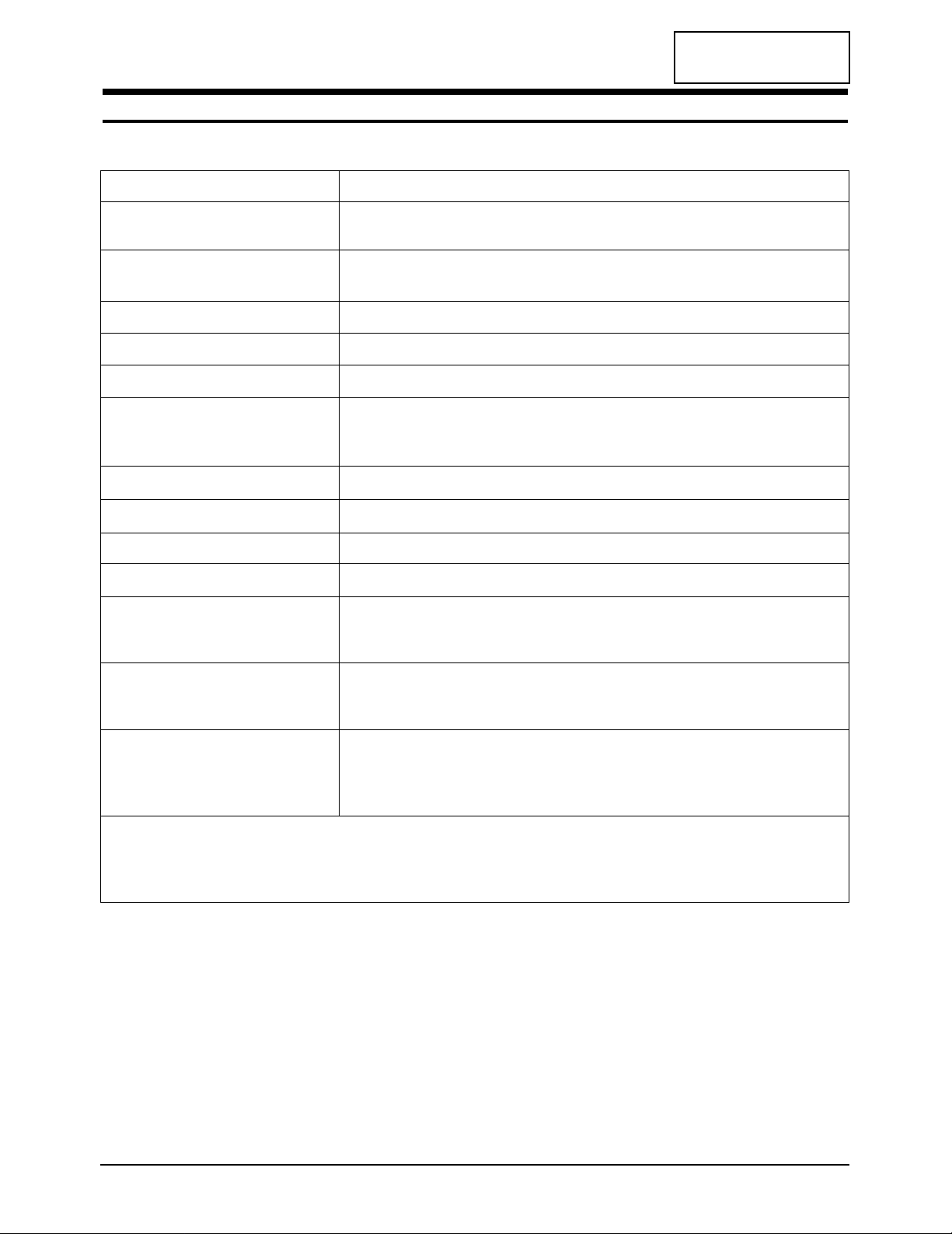
2-1 Specifications
LCD Panel TFT-LCD panel, RGB vertical stripe, normaly white, 15-Inch viewable,
0.297 mm pixel pitch
Scanning Frequency Horizontal : 31 kHz ~ 60 kHz (Automatic)
Vertical : 56 Hz ~ 75 Hz (Automatic)
Display Colors 16.2 M
Maximum Resolution Horizontal : 1024 Pixels Vertical : 768 Pixels
Input Video Signal Analog, 0.7 Vp-p ± 1% positive at 75 Ω, internally terminated
Input Sync Signal Type : Seperate H/V sync, Composite H/V, Sync-on-Green, automatic synchronization
without external switch of sync type
Level :TTL level
Maximum Pixel Clock rate 80 MHz
Active Display Horizontal/Vertical 304.1 mm / 228.1 mm
AC power voltage & Frequency AC 90 ~ 264 Volts, 60/50 Hz ~ 12 V/3 A
Power Consumption 30 W (MAX)
Dimensions / Unit Weight / incl.Carton
Unit (W x D x H) 357.5 x 184.5 x 360.6 mm (14.1 x 7.3 x 14.2 inches)
Carton (W x D x H) 440 x 363 x 145 mm (17.3 x 14.3 x 5.7 inches)
Weight (Net/Gross)
Normal Stand 2.9 kg (6.4 lbs) / 4.6 kg (10.1 lbs)
Multi Stand 2.98 kg (6.6 lbs) / 4.68 kg (10.3 lbs)
Environmental Considerations Operating Temperature : 50 °F ~ 104 °F (10 °C ~ 40 °C)
Humidity : 10 % ~ 80 %
Storage Temperature : 13 °F to 113 °F (-25 °C ~ 45 °C)
Humidity : 5 % ~ 95 %
•MO15E* complies with SWEDAC (MPR II) recommendations for reduced electromagnetic fields.
•Designs and specifications are subject to change without prior notice.
MO15E* 2-1
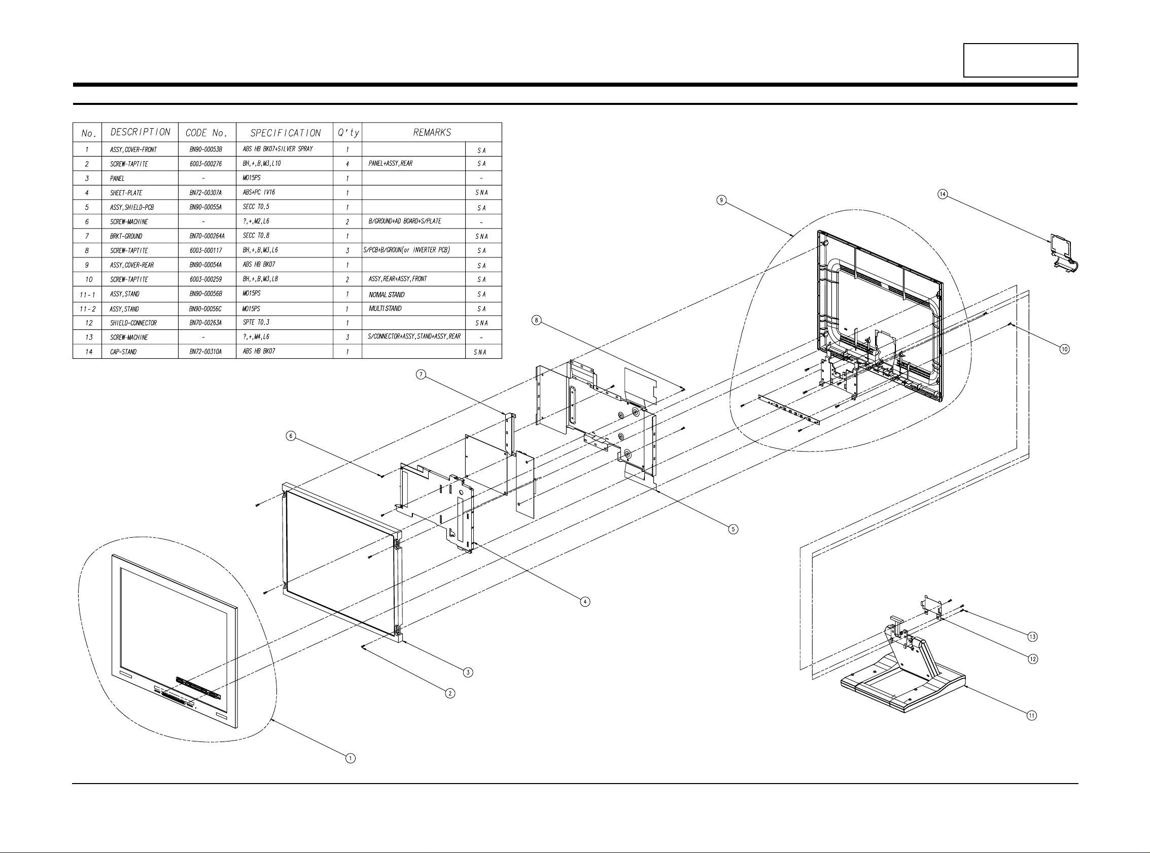
Item Description
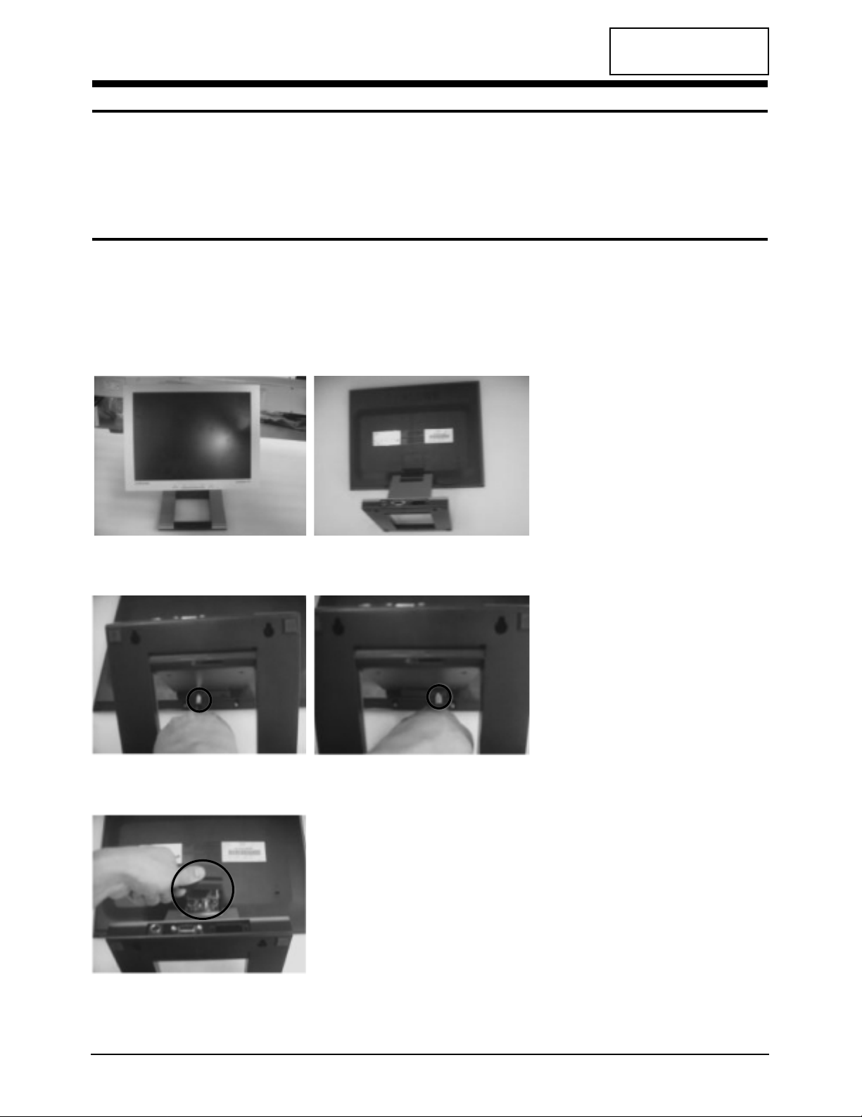
1. Locate the monitor on the table
with face down.
2. Loose the snaps of Hinge cap
through the slot of Cover Rear.
3. Remove the hinge cap.
CONFIDENTIAL
MO15E* 3-1
3 Disassembly and Reassembly
This section of the service manual describes the disassembly and reassembly procedures for the
MO15E* monitors.
WARNING: This monitor contains electrostatically sensitive devices. Use caution when handling
these components.
3-1 Disassembly
Cautions:1. Disconnect the monitor from the power source before disassembly.
2. Follow these directions carefully; never use metal instruments to pry apart the cabinet.
3-1-1 Main Body Disassembly
CONFIDENTIAL
MO15E* 4-1
4 Troubleshooting
Notes: 1. Before troubleshooting, setup the PC’s display as below.
• Resolution: 1024 x 768
• H-frequency: 48 kHz
• V-frequency: 60 Hz
2. If no picture appears, make sure the power cord is correctly connected.
3. Check the following circuits.
• No raster appears: SMPS PCB, Main PCB
• 14V develop but no screen: Main PCB
• 14V does not develop: SMPS PCB
4. If you push and hold the “EXIT” button for more than 5 seconds, the monitor automatically turns back
to the factory preset.
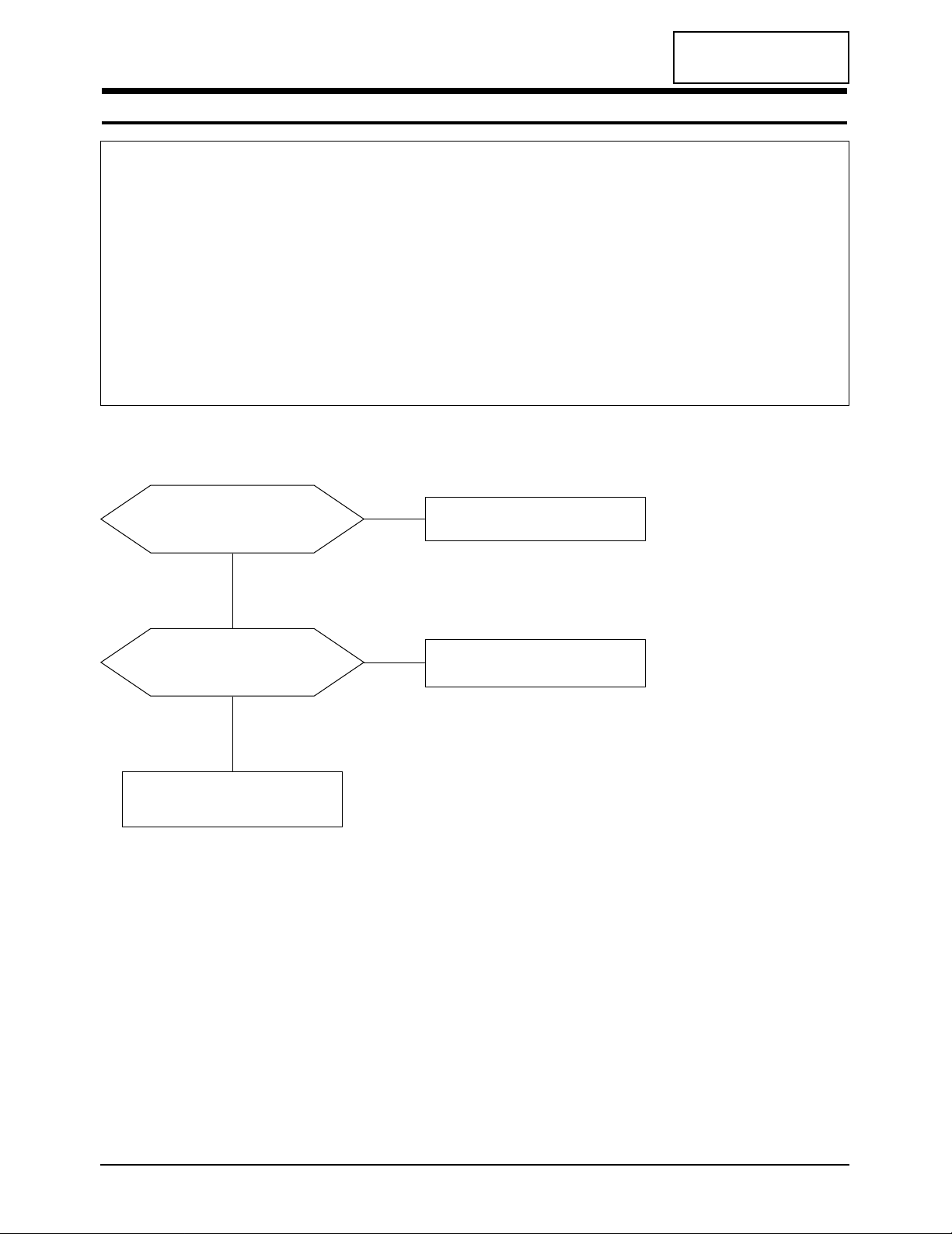
4-1 No Power
Does proper DC 14 V appear at
Pin 1, 2 or Pin 3 of CN202?
Check SMPS.
Yes
No
Does proper DC 3.3 V appear at
Pin 4 of IC100?
Check IC100.
Check IC101, IC301, IC500 or IC602.
Yes
No
MO15E* 5-1
CONFIDENTIAL
5 Exploded View and Parts List

CONFIDENTIAL
MO15E* 6-1
- BN94-00302A ASSY PCB MAIN MO15ES SNA
CIS BH73-60304E RUBBER-SUPPORT MO15PS,CR V0,6*6*6.4,BLACK SNA
CIS BN39-00002A CBF-HARNESS -,60,BLU/WHT,-,26,- SNA
CIS BN39-00251A LEAD CONNECTOR ASSY
MO15ES,UL1571#30,UL/CSA,20P,#30,12507HS-20,12507HS-20,BK,40MM,1571#30,SJ01-01-33
CIS BN44-00066A INVERTER MO15PS,SIC581,48KHZ,14VDC,2.6MARMS,6.1MARMS,48KHZ,140*50*8.0,4LAMP
CIS BN70-00264A PLATE-BRKT GROUND MO15PS,SECC,-,T0.8,-,-,-,-,MO15PS SNA
CIS BN72-00307A PLATE-PCB MO15PS,ABS+PC,IV16,-,-,5V,-,-,- SNA
CIS6 BN63-00265A GASKET
MO15PS,CONDUCTIVE FABLIC,4MM,10MM,17MM,GRAY,71TSSK 10-4-17-13,71TSSK 10-4-17-13
SNA
CIS7 BN63-00266A GASKET
MO15PS,CONDUCTIVE FABLIC,4MM,4MM,60MM,GRAY,71TTSK 4-4-60-13,71TTSK 4-4-60-13
SNA
SH/MO+BR/GR+PCB
6001-001340 SCREW-MACHINE CH,+,M2.0,L4.5,ZPC(YEL),SWRCH18A,FP
- BN97-00094A ASSY SMD MO15ES SNA
C100 2402-001042 C-AL,SMD 100uF,20%,16V,GP,TP,6.6x6.6x5.4mm
C101 2203-005005 C-CERAMIC,CHIP 100nF,10%,16V,X7R,TP,1608
C102 2402-001042 C-AL,SMD 100uF,20%,16V,GP,TP,6.6x6.6x5.4mm
C103 2402-001042 C-AL,SMD 100uF,20%,16V,GP,TP,6.6x6.6x5.4mm
C104 2203-005005 C-CERAMIC,CHIP 100nF,10%,16V,X7R,TP,1608
C105 2203-001652 C-CERAMIC,CHIP 470nF,+80-20%,16V,Y5V,TP,1608
C106 2203-001652 C-CERAMIC,CHIP 470nF,+80-20%,16V,Y5V,TP,1608
C107 2402-001042 C-AL,SMD 100uF,20%,16V,GP,TP,6.6x6.6x5.4mm
C200 2402-001042 C-AL,SMD 100uF,20%,16V,GP,TP,6.6x6.6x5.4mm
C201 2203-000189 C-CERAMIC,CHIP 100nF,+80-20%,25V,Y5V,TP,1608,
C202 2203-000236 C-CERAMIC,CHIP 0.1nF,5%,50V,NP0,TP,1608
C203 2203-000236 C-CERAMIC,CHIP 0.1nF,5%,50V,NP0,TP,1608
C204 2203-005005 C-CERAMIC,CHIP 100nF,10%,16V,X7R,TP,1608
C205 2203-000815 C-CERAMIC,CHIP 0.033nF,5%,50V,NP0,TP,1608
C206 2203-000626 C-CERAMIC,CHIP 0.022nF,5%,50V,NP0,TP,1608
C208 2203-005005 C-CERAMIC,CHIP 100nF,10%,16V,X7R,TP,1608
C210 2203-005005 C-CERAMIC,CHIP 100nF,10%,16V,X7R,TP,1608
C212 2203-005005 C-CERAMIC,CHIP 100nF,10%,16V,X7R,TP,1608
C213 2203-000384 C-CERAMIC,CHIP 0.015nF,5%,50V,NP0,TP,1608
C214 2203-000384 C-CERAMIC,CHIP 0.015nF,5%,50V,NP0,TP,1608
C215 2203-000384 C-CERAMIC,CHIP 0.015nF,5%,50V,NP0,TP,1608
C216 2203-005005 C-CERAMIC,CHIP 100nF,10%,16V,X7R,TP,1608
C217 2402-000108 C-AL,SMD 10uF,20%,16V,WT,TP,4.3x4.3x5.4
C218 2203-005005 C-CERAMIC,CHIP 100nF,10%,16V,X7R,TP,1608
C219 2203-000257 C-CERAMIC,CHIP 10nF,10%,50V,X7R,TP,1608
C220 2402-000108 C-AL,SMD 10uF,20%,16V,WT,TP,4.3x4.3x5.4
C300 2402-000135 C-AL,SMD 22uF,20%,16V,GP,TP,5.3x5.3x5.4
C301 2203-005005 C-CERAMIC,CHIP 100nF,10%,16V,X7R,TP,1608
C302 2203-005005 C-CERAMIC,CHIP 100nF,10%,16V,X7R,TP,1608
C303 2203-005005 C-CERAMIC,CHIP 100nF,10%,16V,X7R,TP,1608
C304 2203-005005 C-CERAMIC,CHIP 100nF,10%,16V,X7R,TP,1608
C305 2402-000135 C-AL,SMD 22uF,20%,16V,GP,TP,5.3x5.3x5.4
C306 2203-005005 C-CERAMIC,CHIP 100nF,10%,16V,X7R,TP,1608
C307 2402-000135 C-AL,SMD 22uF,20%,16V,GP,TP,5.3x5.3x5.4
C308 2203-005005 C-CERAMIC,CHIP 100nF,10%,16V,X7R,TP,1608
C309 2203-000041 C-CERAMIC,CHIP 0.01nF,0.25pF,50V,NP0,TP,1608
C310 2203-000843 C-CERAMIC,CHIP 39nF,10%,25V,X7R,TP,1608,-
Loc. No. Code No. Description Specification Remarks
6 Electrical Parts List
6-1 Main PCB Parts
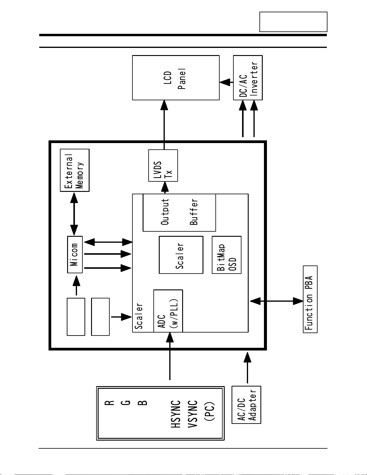
7 Block Diagram
MO15E* 7-1
H V
NT7181F
Brightness
On/Off
+14V
12MHz
12MHz
(Mascot V)
CONFIDENTIAL
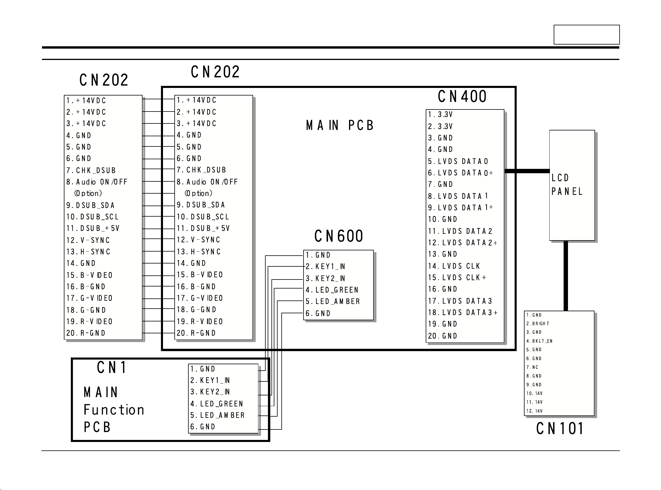
8 Wiring Diagram
MO15E* 8-1
CONFIDENTIAL
8 Wiring Diagram
CONFIDENTIAL
MO15E* 9-1
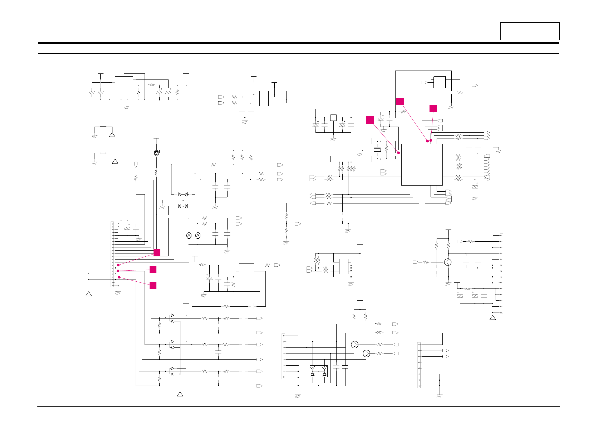
9 Schematic Diagrams
9-1 Schematic Diagram
100nF
R523 100
G-GND
G-VIDEO
B-VIDEO
B-GND
V-SYNC
+14VDC
R-GND
DSUB_+5V
DSUB_SDA
DSUB_SCL
R-VIDEO
CHK_DSUB
DSUB_GND
H-SYNC
P-GND
D202
BZX84C5V1
1
2
3
16V
100uF
C107
75
R216
C703
470nF
16V
MO
C105
470nF
16V
MO
B
C
E
4.7K
R520
+5V
KSC1623-Y
Q601
R215
33
1/16W
R213
C101
MO
100nF
16V
75
MO
16V
470nF
C106
L200
1.5uH
D204
MMBD4148SE
1
2
3
MS_3.3V
R525
100
+5V
8
SK34
D100
slcon8p
1
2
3
4
5
6
7
470nF
16V
CN501
100uF
C705
C501
MS_3.3V
C500
100nF
16V
R206
100
1/16W
C206
22pF
R200
1/16W
10K
R218
680K
10
R100
1/16W
4.7K
R527
R208
16V
470nF
C513
MO
0
C509
50V
470nF
16V
MO
50V
15pF
C511 C512
15pF
E
C220
10uF
Q701
KSC1623-Y
B
C
C601
100nF
R220
4.7K
1/16W
1/16W
33
R209
16V
100nF
C702
100
1/16W
R207
D203
1
2
3
10
R211
100
1/16W
MMBD4148SE
C706
100uF
16V
R606
Vin
16V
100uF
C701
4
F_B
3
GND
6
GND1
ON_OFF
5
OUT
21
R508
18K
IC100
LM2596S-3.3
18K
R509
+5V
100uF
16V
C502
8
C504
16V
100uF
slcon8p
CN600
1
2
3
4
5
6
7
100nF
C210
D1_1
7
6
D2
D2_1
5
2
G1
4
G2
S1
1
S2
3
+5V
1A2
B
SI9933ADY-T1
IC101
8
D1
BLM41P600S
FT701
1.5uHL601
47K
1/16W
R201
R212
1/16W
33
R605
510
1/16W
C215
15pF
50V
Q600
KSC1623-Y
B
C
E
100nF
C505
16V
100
100nF
C503
16V
TP1491
1
R515
R514 0
R702
100
1/16W
R501
10K
1/16W
53uH
L101
R203
1/16W
100
100nFC208
C213
15pF
50V
PANEL_3.3V
75
R210
2
GND
1IN3
OUT
C600
100nF
16V
470nF
C704
IC500
BA17805FP
10K
R101
R102
TP1490
1
10K
R5134.7K
100R516
R502
470
R500
R503
100
R506
100
4.7K
100
0
R519
10R701
R217
R700
4.7K
1/16W
+3.3V
100
R521
100pF
C203
100R507
+5V
R526 100
C508
10uF
R518 1K
R512
R5114.7K
R517
4.7K
A
2
C1
6
C2
4
C33C4
1
NC
5
100
A
6
C1
4
C2
3
C3
1
C4
5
NC
QZX363C5V6
IC601
IC200
QZX363C5V6
2
+5V
R204 100 1/16W
MMBD4148SE
1
2
3
C218
+5V
D205
R524 100
C507
22pF
1/16W
1M
C506
22pF
X501
HC-49/S-SMD(12MHz,30ppm)
Q0Q1
R505
C212 100nF
50V
15pF
C214
R703
10K
1/16W
10uF
C217
+5V
16V
100nF
C216
R214
10
5
6
7
8
50V
C201
100nF
IC202
1
2
3
4
PC7
36
PD0
35
PD1
34
33
PD2
32
PD3
PD4
31
30
PD5
RSTB
4
V33
644
VSYNCI
LM1881M
28
PB427PB526PB625PB7
PC0
3
PC12PC2
142
PC341PC440PC5
PC6
37
PA123PA2
PA322PA421PA520PA619PA7
18
17
PB0
PB1
16
PB2
15
PB3
14
43
HSYNCI
NC1
38
NC2
39
9
OSCI
8
OSCO
10
P30
11
P31
12
P34
P35
13
29
PA0
24
+5V
NT68F63L
IC501
CVV
5
7
GND
47K
R202
1/16W
+14V
C205
33pF
50V
1/16W
510
R604
C202
100pF
10nF
50V
C219
MO
100nF
16V
C104
1.5uH
L201
12
13
14
MS_3.3V
C100
100uF
16V
2
3
4
5
6
7
8
9
10
11
+14V
CN101
slcon14p_1
1
1/16W
10K
R504
L600 1.5uH
C102
16V
100uF
1
NC5VCC
Y
4
1/16W
100
R607
NC7SZ14M5X
IC201
A
2
GND
3
1
2
3
+14V
16V
100nF
C204
BZX84C5V1
D201
C103
100uF
16V
C200
16V
100uF
C510
100nF
7
8
+5V
+14V
1/16WR205 100
M24C08-WMN1T
IC502
1
2
3
4
5
6
D200
A
1
2
B
3
C
+3.3V
BZX84C5V1
14
15
16
17
18
19
20
21
22
10
R219
4
5
6
7
8
9
10
11
12
13
CN202
slcon22p_1
1
2
3
SDA
SCL
LED_B
H*V_SYNC
A_H*V_SYNC
H*V_SYNC
SEL_MDL
MS_IRQ*
KEY1_IN
CHK_DSUB
MS_RESET*
CHK_DVI
*PANEL_EN
*DPMS_ON
BRIGHT
KEY2_IN
MS_SCL
MS_SDA
GREEN
AMBER
V_SYNC
H_SYNC
LED_A
DDC_DATA
DDC_CLK
INV_GND
*LVDS_EN
A_V_SYNC
*BKLT_EN
SOG_SYNC
AGND
AGND
AGND
AGND
MS_SCL
MS_SDA
SOG_SYNC
*BKLT_EN
KEY1_IN
KEY2_IN
*PANEL_EN
*DPMS_ON
SCL
SDA
BRIGHT
*BKLT_EN
SEL_MDL
INV_GND
AGND
RED+
A_H*V_SYNC
A_V_SYNC
DDC_DATA
DDC_CLK
AGND
BLU+
GRN+
CHK_DSUB
AMBER
GREEN
13
15
14
10
11
8
SEC LT140X1-002 BN07-00004A SA BN68-00187A
SEC LT150XS-L01 BN07-00009A SB BN68-00187B
SEC LT150XS-L01-B BN07-00022A SC BN68-00187C
SEC LTM150XS-L02 BN07-00005A SD BN68-00187D
SEC LT181E2-132 BN07-00001A SE BN68-00187E
SEC LT150XS-T01 BN07-00010A SF BN68-00187F
SEC LTM181E3-132 BN07-00019A SG BN68-00187G
SEC LT170E2-131 BN07-10001D SH BN68-00187H
SEC LT181E2-131 BN07-10001E SJ BN68-00187J
SEC LTM170E4-L01 BN07-00018A SK BN68-00187K
SEC LTM240W1-L01 BN07-00015A SL BN68-00187L
SEC LTM213U3-L01 BN07-00016A SM BN68-00187M
SEC LTM150XH-L01 BN07-00026A SN BN68-00187W
SEC LTM150XH-L03 BN07-00027A SP BN68-00187X
SEC LTM150XS-L01 BN07-00032A SQ BN68-00195B DELL(ZPD)
SEC LTM181E4-L01 BN07-00034A SR BN68-00195C PVA
SEC LTM170EH-L01 BN07-00036A SS BN68-00195D TN
SEC LTM170E5-L01 BN07-00037A SU BN68-00195E PVA
SEC LTM150XH-L11 BN07-00041A SV BN68-00195G
SEC LTM213U4-L01 BN07-00039A SW BN68-00195L PVA
SEC LTM150XH-L01(ZPD) BN07-00045A SX BN68-00195M ZPD
SEC LTM150XH-L04 BN07-00046A SY BN68-00195N PANEL
SEC LTM170W1-L01 BN07-00047A SZ BN68-00195P TV PANEL
SEC LTM150XH-L06 BN07-00053A EA BN68-00195V TV PANEL/450cd Sony& EOS panel
SEC LTM153W1-L01 BN07-00054A EB BN68-00195W NIKE MODEL
SEC LTM170EH-L05 BN07-00055A EC BN68-00195X 17” EH-L05 panel EOS proj.
SEC LTM170E5-L03 BN07-00056A ED BN68-00195Y Dell 1702FP pro. E4 Compatible
SEC LTM190E1-L01 BN07-00057A EE BN68-00195Z DELL 1900 FP
SEC LTM181E5-L01 BN07-00061A EF BN68-00239C 18” narrow bezel GH18PS
SEC LTM150XP-L01 BN07-00065A EG BN68-00239F AMLCD PVA PANEL
SEC LTM240W1-L02 BN07-00062A EH BN68-00239G 15” Wide tv panel
TOSHIBA LTM15C419(A) BN07-00002A TA BN68-00187N
TOSHIBA LTM15C423(B) BN07-00006A TB BN68-00187P
TOSHIBA LTM18C161 BN07-00008A TC BN68-00187U
TOSHIBA LTM15C443 BN07-00031A TD BN68-00195A
TOSHIBA LTM15C458 BN07-00043A TE BN68-00195H
HANNSTAR HSD150MX41A(A) BN07-00020A NA BN68-00187Q TTL
HANNSTAR HSD150MX12 BN07-00030A NB BN68-00187Y LVDS
TORISAN TM150XG-22L03(A) BN07-00021A RA BN68-00187R
TORISAN TM150XG-26L06 BN07-00042A RB BN68-00195J
TORISAN TM181SX-76N01 BN07-00048A RC BN68-00195Q
TORISAN TM150XG-22L06 BN07-00059A RD BN68-00239A 15” XGA TN MODE(ZPD)
TORISAN TM290WX-71N31 BN07-00063A RE BN68-00239D RS24NS (TORISAN 29” NEW PANEL)
TORISAN TM396WX-71N31 BN07-00064A RF BN68-00239E RS24NS (TORISAN 40” NEW PANEL)
SHARP LQ181E1DG11(A) BN07-10001C PA BN68-00187S
HITACHI TX38D12VC0CAA(A) BN07-00003A HA BN68-00187T
HITACHI TX43DVCOCAB BN07-00060A HB BN68-00239B 17” SXGA PVA MODE
IBM ITSX94S BN07-00017A IA BN68-00187V
UNIPAC UM170E0 BN07-00028A UA BN68-00187Z
HYUNDAI HT15X13 BN07-00035A DA BN68-00195F
HYUNDAI HT17E11-200 BN07-00049A DB BN68-00195R TN MODE
ACER L170E3 BN07-00044A AA BN68-00195K TN(ADT)
CHIMEI M170E3-LO1 BN07-00050A CA BN68-00195S TN PANEL
CHIMEI M150X3-L01 BN07-00051A CB BN68-00195T COMPATIBLE
CHIMEI M170E4-L01 BN07-00052A CC BN68-00195U MVA PANEL
MO15E* 10-1
CONFIDENTIAL
Maker VENDOR P/N PANEL_CODE PANEL_ABB STICKER_CODE Remarks
10 Panel Description

CONFIDENTIAL
MO15E*
Copyright
© 2002 by Samsung Electronics Co., Ltd.
All rights reserved.
This manual may not, in whole or in part, be
copied, photocopied, reproduced, translated, or
converted to any electronic or machine readable
form without prior written permission of
Samsung Electronics Co., Ltd.
MO15E* Service Manual
First edition March 2002.
Printed in Korea.
Trademarks
Samsung is a registered trademark and
MO15E* and MacMaster Cable Adapter are
trademarks of Samsung Electronics Co., Ltd.
Macintosh, Centris, Quadra, Duo Dock, and
Power Macintosh are trademarks of Apple
Comprter, Inc.
All other trademarks are the property of their
respective owners.
ii
 Loading...