

Samsung MIM-H03 User & Installation Manual

Smart AC application
MIM-H03
Multi Wi-Fi kit
user & installation manual
imagine the possibilities
Thank you for purchasing this Samsung product.

This product is the Smart Air conditioner which supports Samsung Smart Home Service.
Contents
Safety precautions ....................................................................................................... 3
Check before installing Wi-Fi kit .......................................................................................... 4
Parts......................................................................................................................4
Exterior dimension........................................................................................................4
How to install Wi-Fi kit ................................................................................................... 5
Wi-Fi kit installation.......................................................................................................5
Checking the Wi-Fi kit...................................................................................................10
Initializing user data ....................................................................................................11
Updating the Wi-Fi kit by SD card .......................................................................................11
Setting the network .................................................................................................... 12
Specication of wired/wireless router for Samsung Smart Air conditioner................................................12
Starting Samsung Smart Home App .................................................................................... 13
Downloading Samsung Smart Home App............................................................................... 13
Running the Samsung Smart Home App ................................................................................13
Connecting the air conditioner to Samsung Smart Home app ...........................................................13
Starting System Air conditioner App .................................................................................... 14
Controlling the air conditioner with Samsung Smart Home app .........................................................14
Troubleshooting ........................................................................................................ 15
Specications ........................................................................................................... 16
Open Source Announcement ........................................................................................... 16
2
Safety precautions
This installation manual explains how to install a Wi-Fi kit to an indoor unit of Samsung system air conditioners.
Read the installation manual thoroughly before installing the Wi-Fi kit.
(Refer to the appropriate manual for installing product or other optional parts.)
WARNING
Hazards or unsafe practices that may result in severe personal injury or death.
ENGLISH
CAUTION
Hazards or unsafe practices that may result in minor personal injury or property damage.
WARNING
Contact service center for installation.
- There is a risk of product malfunction, water leakage, electric shock or re.
Install the Wi-Fi kit securely in a place that can withstand the weight of the product.
- If the installation location is not strong enough, Wi-Fi kit may fall and be damaged.
Connect the power with rated voltage when installing.
- If not, there is risk of re or damage to the Wi-Fi kit.
Do not attempt to move or re-install the Wi-Fi kit that is already installed.
- There is risk of electric shock and re.
Do not attempt to modify or repair the Wi-Fi kit on your own.
- There is potential risk of product damage, electric shock or re. When repair is needed, consult service center.
Check if the installation was done properly according to the installation manual.
- If the Wi-Fi kit is installed incorrectly, there is risk of electric shock or re.
Make sure that all wiring work is done by a qualied person complying with regional standards and instructions in this
manual.
- If the installation is done by unqualied person, there is risk of product malfunction, electric shock or re caused by
incorrect installation.
Contact the service center if you need to dispose the Wi-Fi kit.
CAUTION
Do not install the product in a place where it is or might be exposed to inammable gas leakage.
- There is risk of re or explosion.
Do not install the product in a place where it will be exposed to oil or vapor etc.
- If the product is used in a place where it is exposed to oil, vapor or sulphur dioxide, parts of the product may get
damaged or product may function abnormally.
Make sure that water does not get into the Wi-Fi kit.
- There is risk of electric shock and re.
Make sure there is no tension to the cable during installation.
- Cable may get cut and cause re.
Install the product in a place with temperature between 0 °C~39 °C (32 °F~102 °F) with no direct sunlight.
- If not, there is risk of electric shock or abnormal operation.
Do not install the product in a place where special spray or acid/alkali solution is used.
- There is risk of electric shock or abnormal operation.
Do not press the button with sharp object.
- There is risk of electric shock or damaging the parts.
Do not connect the power cable to the communication cable terminal.
- There is risk of re.
When installing the product in hospitals or other places, make sure that the product does not interrupt with other
products.
- Abnormal operation may occur.
3
Check before installing Wi-Fi kit
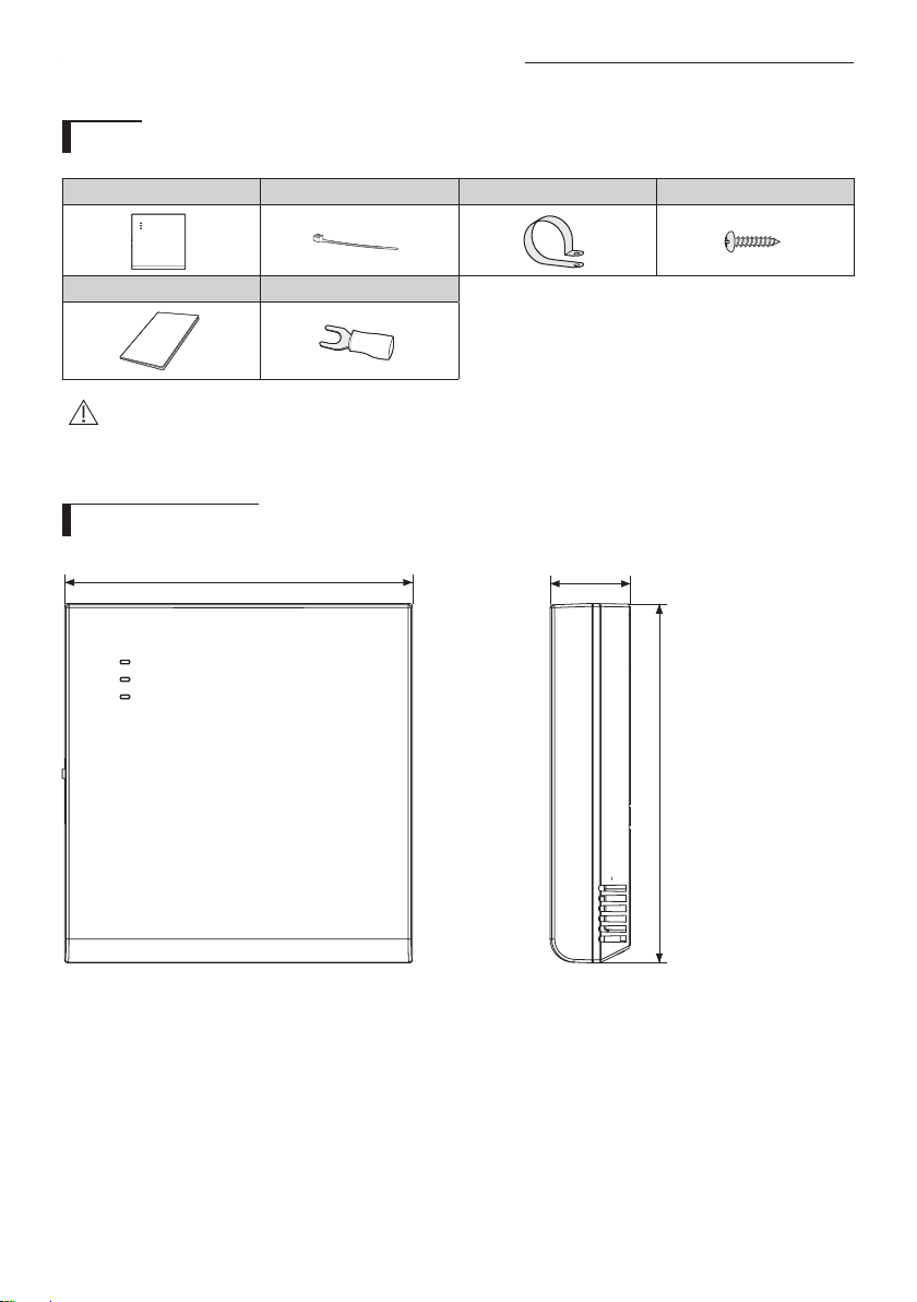
Parts
Assy Wi-Fi kit Cable tie (2) Cable clamp (3) M4×16 screw (5)
User & Installation manual U- terminal (6)
• Wi-Fi kit should be installed by a certied installer.
• Before installing a Wi-Fi kit, you should check whether the power of the kit is turned o.
CAUTION
• The wire of Wi-Fi kit should be installed in accordance with electric wiring regulation and should also be installed
inside the wall so that it cannot be touched by users.
Exterior dimension
120 (4 3/4)
29 (1 1/8)
Unit : mm (inches)
124 (4 7/8)
4
How to install Wi-Fi kit
Wi-Fi kit installation
• For smooth operation, install the Wi-Fi kit and the wireless router in open space with no obstacles between them.
Operation may not be possible if the distance between the Wi-Fi kit and the wireless router is too far or if there's any
CAUTION
obstacle between them.
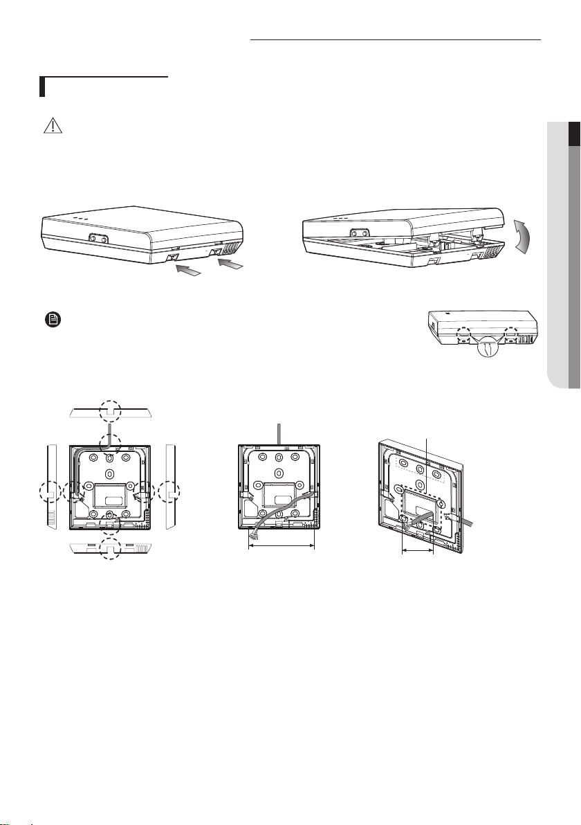
1. After pushing the two hooks on the bottom of the Wi-Fi kit at the same time, lift the front cover up and then detach it
from the rear cover.
Push the two hooks at the same time.
• It might be easier to disassemble the Wi-Fi kit if you put a at-head screw driver
into the square hole above the xing hook.
NOTE
2. Place the power wire and communication wire through openings in the rear cover.
The opening can be cut and
removed if you need more
space.
ENGLISH
15 cm
(5 7/8 inches)
<When the cover is not recessed> <When the cover is recessed>
10 cm
(3 15/16 inches)
5
How to install Wi-Fi kit
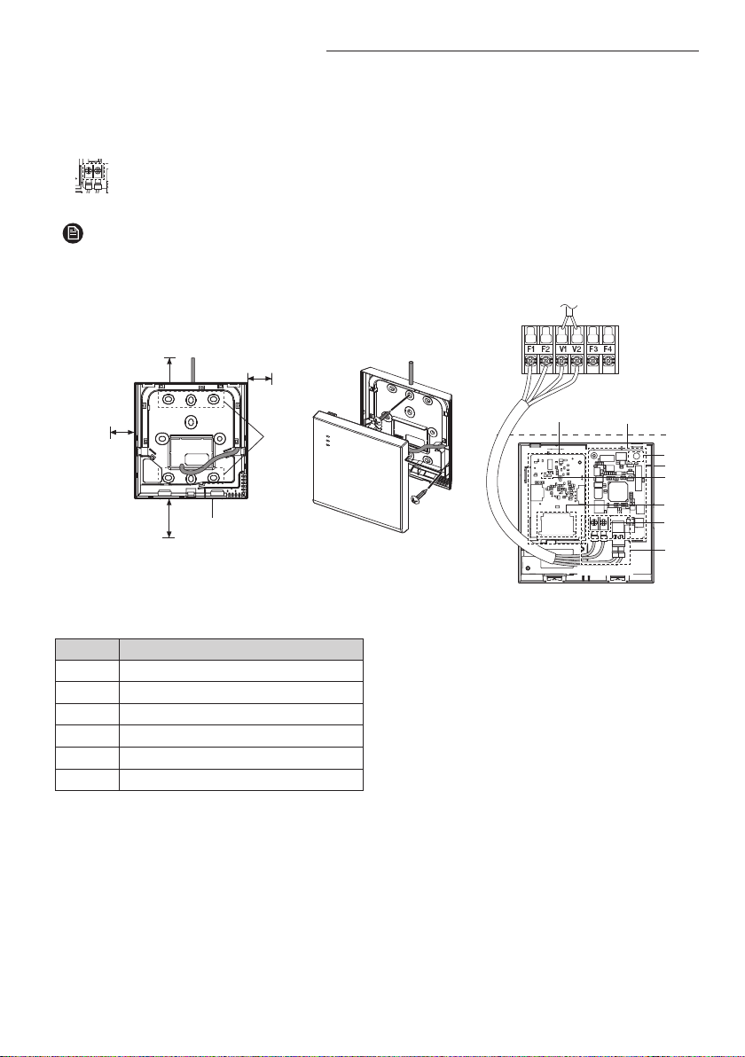
3. Use two or more screws to x the rear cover of the Wi-Fi kit to a wall. Then, connect the power cable (V1, V2) and the
communication cable(F1, F2) to the terminals on the back of the front cover in appropriate length.
4. When connecting the V1 and V2, tighten the screws for the terminal block (CN5) with a tightening torque of 5 ±2 Kgf·cm.
Size of the screw is M3 x 6.
• Maximum number of indoor unit installation that can be connected to Wi-Fi kit is 16.
• One Wi-Fi kit can be registered with maximum 5 users.
NOTE
- If you register more than 5 users to single Wi-Fi kit, its operation may become slower.
• Each account (one mobile phone) can be registered with maximum 4 Wi-Fi kits.
Indoor unit
(9/16inch) or more
(9/16inch) or
10 mm
10 mm
more
50 mm (2inches)
or more
(9/16inch) or more
Rear cover
Before xing the rear cover, allow
10mm or more space for upper,
left, and right sides and 50mm
space for bottom side.
Item Contents
Power/communication connection terminal
Ⓐ
Tracknig/Initializing button
Ⓑ
SD Card Slot
Ⓒ
LED
Ⓓ
Network PBA
Ⓔ
Interface module PBA
Ⓕ
10 mm
Screw
xing
hole
Fix the screws in the
provided screw holes.
Ⓔ Ⓕ
Ⓑ
Wi-Fi kit
Ⓓ
Ⓒ
Ⓐ
PCB
V1 V2 F1 F2
terminal
Do not tighten the PCB terminal with
too much force.
6

5. Reassemble the Wi-Fi kit.
• Put the front cover of the kit into the upper grooves rst and then t it as shown in the picture. After
assembling the Wi-Fi kit, please check if there is any gap because of the connection cable between
NOTE
front cover and rear cover.
Connection diagram of Wi-Fi kit
ENGLISH
F1
< Connecting the Wi-Fi kit to a multi type product >
F1 F1
F2 F2
F1 F1 V1V1 F1F2
F2 F2 V2V2 F2F1 F2
7
 Loading...