

Samsung MIM-E03 series Installation Manual

EHS Control unit_MIM-E03@_IM_E_34413-2.indd 40 2012-04-05 오후 1:20:13

MIM-E03
SAMSUNG CONTROL KIT
installation manual
imagine the possibilities
Thank you for purchasing this Samsung product.
To receive more complete service, please
register your product at
www.samsung.com/register
E S F I P D
DB98-34413A(2)
EHS Control unit_MIM-E03@_IM_E_34413-2.indd 41 2012-04-05 오후 1:20:14

2
Contents
Safety precautions . .. . .... . .... . . .... . .... . . .... . .... . ..... . .... . ..... . .... . .... . . .... . .... . . .... . .... . ..... . .... . ..... . . 3
Product specifications . .... . ..... . .... . ..... . .... . .... . . .... . .... . . .... . .... . ..... . .... . ..... . .... . .... . . .... . .... . . .... . 4
Main components .... . . .... . .... . ..... . .... . ..... . .... . .... . . .... . .... . . .... . .... . ..... . .... . ..... . .... . .... . . .... . .... . 4
Installing the unit . .. . .... . . .... . .... . ..... . .... . ..... . .... . .... . . .... . .... . . .... . .... . ..... . .... . ..... . .... . .... . . .... . .. 5
Wiring works . . ..... . .... . ..... . .... . .... . . .... . .... . . .... . .... . ..... . .... . ..... . .... . .... . . .... . .... . . .... . .... . ..... . .. 7
Wiring schematics . . ... . .... . ..... . .... . .... . . .... . .... . . .... . .... . ..... . .... . ..... . .... . .... . . .... . .... . . .... . .... . .... 31
Setting option switches and function of keys . . ... . .... . .... . . .... . .... . . .... . .... . ..... . .... . ..... . .... . .... . . .... . .... . 32
Before running the system . . ... . .... . . .... . .... . . .... . .... . ..... . .... . ..... . .... . .... . . .... . .... . . .... . .... . ..... . .... . . 36
Troubleshooting . . . .... . .... . . .... . .... . . .... . .... . ..... . .... . ..... . .... . .... . . .... . .... . . .... . .... . ..... . .... . ..... . ... 37
Error codes ... . . .... . .... . ..... . .... . ..... . .... . .... . . .... . .... . . .... . .... . ..... . .... . ..... . .... . .... . . .... . .... . . .... . . 38
EHS Control unit_MIM-E03@_IM_E_34413-2.indd 2 2012-04-05 오후 1:19:55

3
ENGLISH
Safety precautions
Carefully follow the precautions listed as below because they are essential to guarantee the safety of SAMSUNG product.
WARNING
• Always disconnect a power supply of Air-Water Heat Pump before servicing it or accessing
components inside the unit.
• Verify that installation and testing operations shall be performed by qualified personnel.
• To prevent serious damage on the system and injuries to users, precautions and other
notices shall be observed.
Warning
Carefully read the contents of this manual before installing the control kit and store the manual in a safe place in order to
be able to use it as reference after installation.
For maximum safety, installers should always carefully read the following warnings.
Store the manual in a safe location and remember to hand it over to the new owner if the kit is sold or transferred.
The kit is compliant with the requirements of the Low Voltage Directive (72/23/EEC), the EMC Directive (89/336/EEC) and
the Directive on pressurized equipment (97/23/EEC).
The manufacturer shall not be responsible for damage originating from unauthorized changes or the improper
connection of electric and hydraulic lines. Failure to comply with these instructions or to comply with the requirements
set forth in the “Operating limits” table, included in the manual, shall immediately invalidate the warranty.
Do not use the units if you see some damages on the units and recognize something bad such as loud noisy, smell of
burning.
In order to prevent electric shocks, fires or injuries, always stop the unit, disable the protection switch and contact
SAMSUNG’s technical support if the unit produces smoke, if the power cable is hot or damaged or if the unit is very noisy.
Always remember to inspect the unit, electric connections, and protections regularly. These operations shall be
performed by qualified personnel only.
The unit contains various electric parts, which should be kept out of the reach of children.
Do not attempt to repair, move, alter or reinstall the unit by unauthorized personnel, these operations may cause product
damage, electric shocks and fires.
Do not place containers with liquids or other objects on the unit.
All the materials used for the manufacture and packaging of the air to water heat pump are recyclable.
The packing materials must be disposed of in accordance with local regulations.
Wear protective gloves to unpack, move, install, and service the unit to avoid your hands being injured by the edge of the
parts.
Do not touch the internal parts while running the units.
Inspect the product shipped and check if damaged during transport. If the product has some damages, DO NOT INSTALL
and immediately discuss about the damages with the carrier or retailer (if the installer or the authorized technician has
collected the material from the retailer.)
Our units shall be installed in compliance with the spaces described in the installation manual, to ensure accessibility
from both sides and allow repairs or maintenance operations to be carried out. If the units installed without complying
with procedures described in manual, additional expenses can be asked because special harnesses, ladders, scaffolding
or any other elevation system for repair service will NOT be considered part of the warranty and will be charged to the
end customer.
When service works required, make sure to disconnect the power supply at least 1 minute to prevent electric shocks.
- Always check the voltage at the terminals of main PCB before trying to touch.
Use electric wires which manual designated. Connections between wires and terminals shall be assembled without any
tension. If the assembly works is not implemented well, it can lead to have product damages and fires.
After wiring works, terminal block cover shall be fixed firmly. Without cover, it can cause to have product damage and fire.
EHS Control unit_MIM-E03@_IM_E_34413-2.indd 3 2012-04-05 오후 1:19:55
4
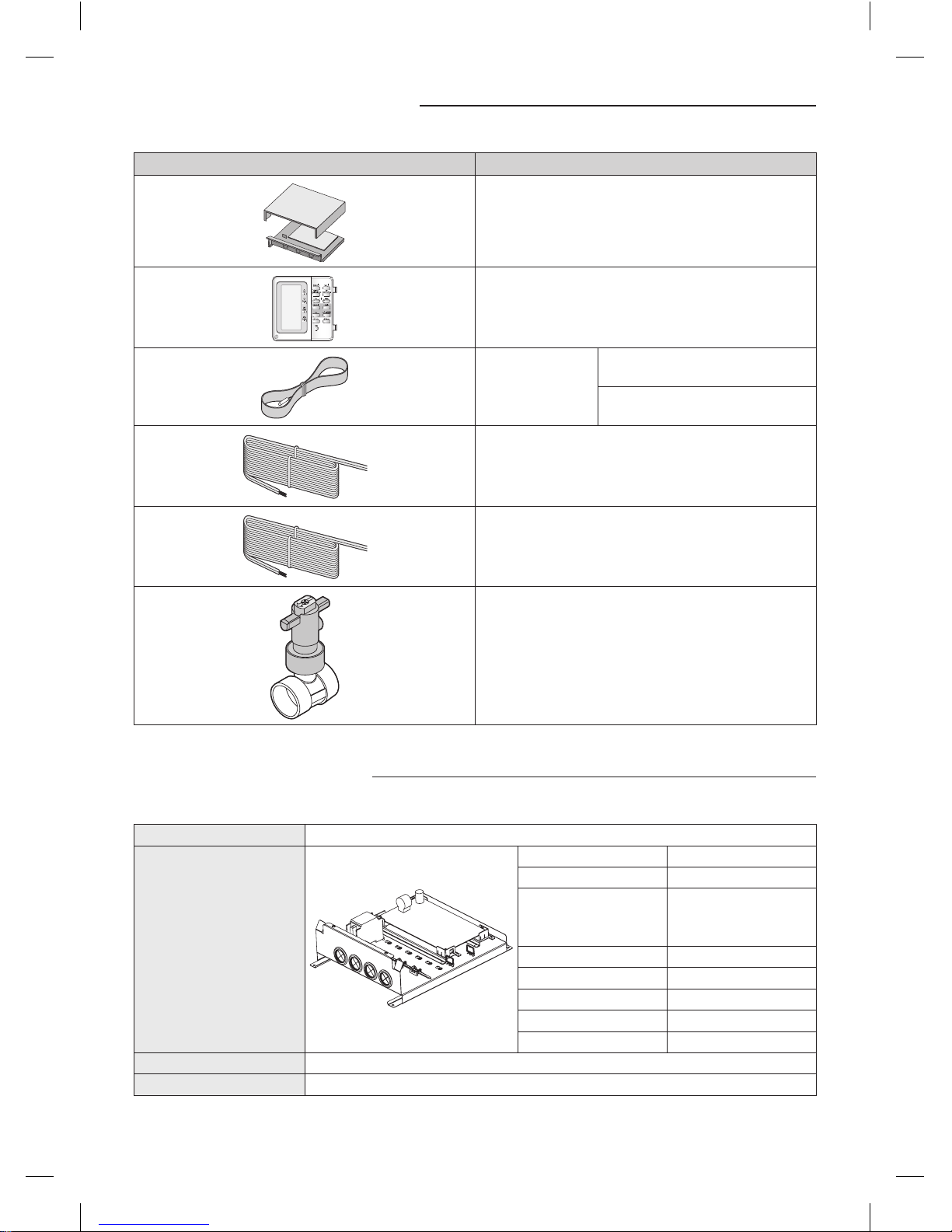
Product specifications
Item Description
MIM-E03A
Wired remote controller
Temp. Sensor
blue cable(15m) for DHW
red cable(15m) for backup heater
Remote controller cable (1EA, 10m)
Smart Grid cable (1EA, 2m)
Flow Switch (1EA, 2m)
(Set point : Min. 16LPM)
Temp. sensor = Temperature sensor
Main components
Model name MIM-E03A
Detail components
Parts Qty.
Main PBA 1
ELCB
- Rated current : 30A
- Leakage current : 30mA
1
Grounding screw 6
Rubber 4
Base plate 1
Top cover plate 1
Case screw 2
Weight (Net) 3.5kg
Packing size (W x H x D) 329mm x 439mm x 168mm
EHS Control unit_MIM-E03@_IM_E_34413-2.indd 4 2012-04-05 오후 1:19:56
5
ENGLISH
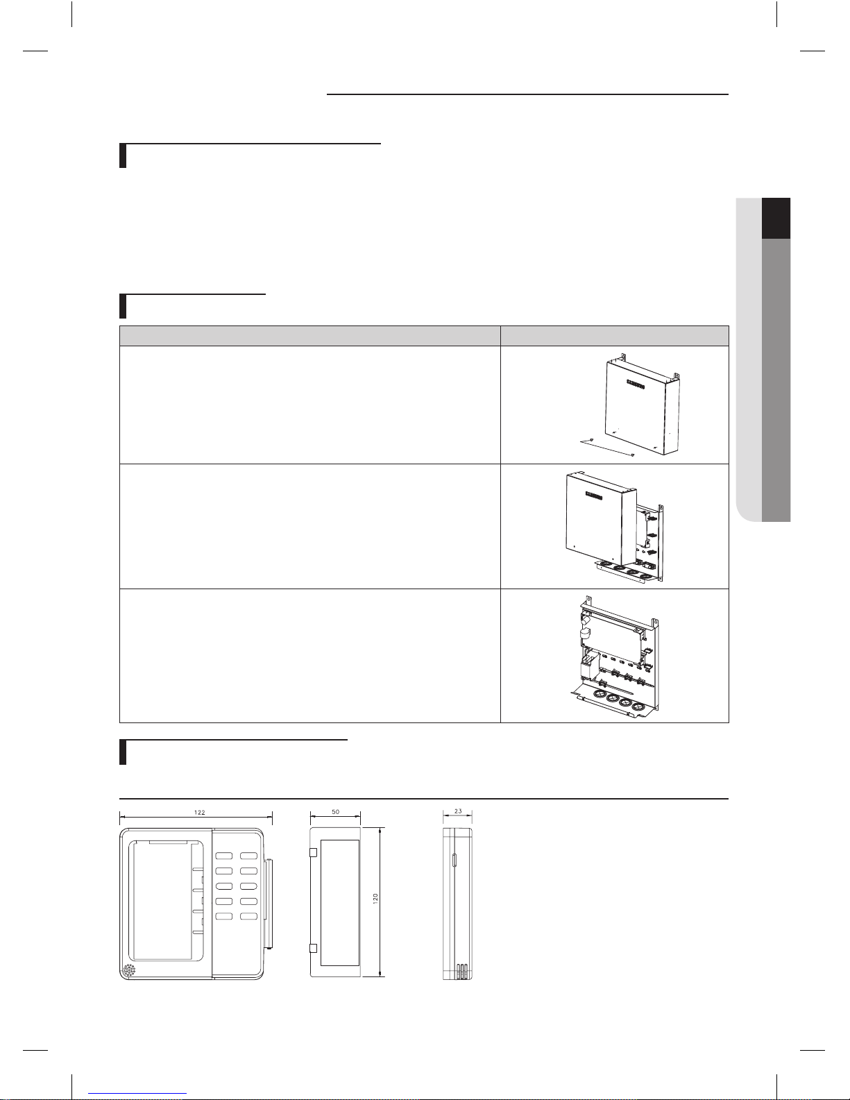
Installing the unit
Deciding on where to install the unit
Install the unit in indoor and do not install it outside. The unit is designed only for indoor.
Direct heat can make the kit have some failures in operation.
Choose locations that are dry and sunny, but not exposed to direct sunlight or strong winds.
Choose location where pipes and cables can be easily connected to the indoor unit.
Avoid locations where flammable elements and explosive chemicals are stored.
Choose a specific wall which can withstand the weight of unit and an external force.
Mounting the unit
Procedure Remark
1. Remove 2 bolts from the unit.
Bolt
2. Open the top cover and install 4 screws on the wall.
3. Close the top cover and install 2 bolts again into the unit.
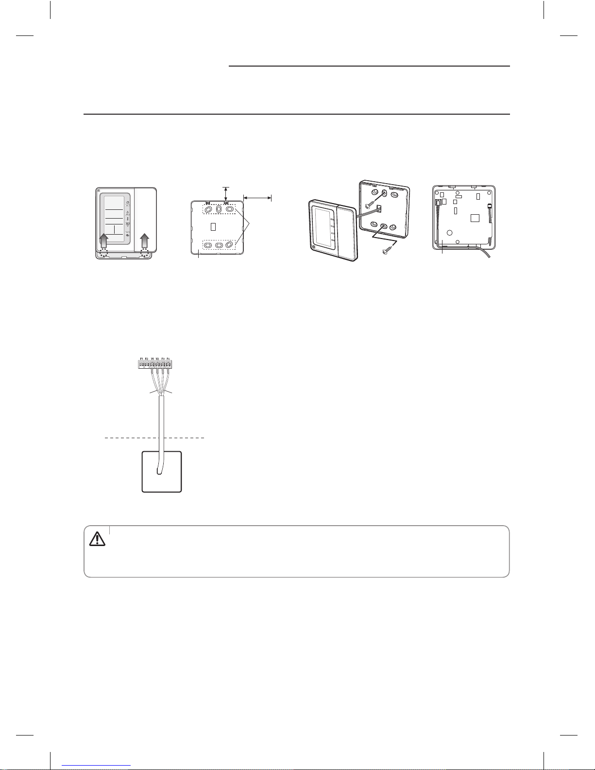
Installing the remote controller
Dimension
(Unit : mm)
EHS Control unit_MIM-E03@_IM_E_34413-2.indd 5 2012-04-05 오후 1:19:56
6
Installing the unit
Installation
1. Open the wired remote controller by pushing up the top cover of the remote controller while holding the rear cover
firmly. The wired remote controller opens in the way of slide.
2. Install the rear cover of the wired remote controller on the wall with the supplied screws. After that, arrange the power
cables on rear side of the front cover.
Screw hole
Rear cover
More than
60mm
More than
30mm
Front cover
Before fixing the rear cover, clear
30mm of space on the top and
60mm on the right side.
Fasten the screw in the
screw hole.
3. Connect the orange and brown wires from the wired remote controller to the power cable (V1, V2) of indoor unit.
Connect the red and black wires to the communication cable (F3, F4) of indoor unit.
Terminal type cable connection
Communication cable
(F3, F4)
Indoor unit
Multi function
wired remote
controller
Power cable
(V1, V2)
4. Reassemble the wired remote controller.
When you reassemble the wired remote controller, match the grooves on the left side.
• When using an extension cable, make sure that the communication cable and the power cable is installed
separately. (If not, it may cause malfunction of the wired remote controller.)
• Power cable of the wired remote controller(V1,V2) should be connected to the one indoor unit only.
CAUTION
EHS Control unit_MIM-E03@_IM_E_34413-2.indd 6 2012-04-05 오후 1:19:56
7
ENGLISH
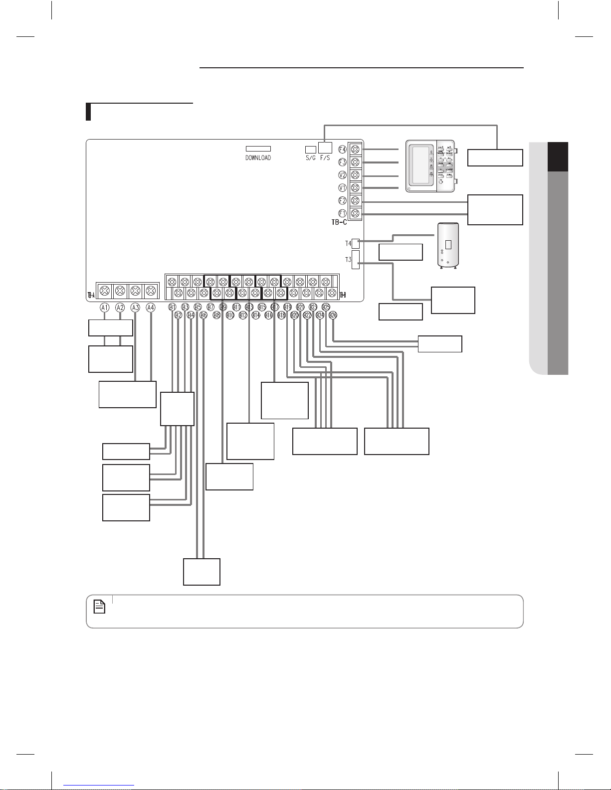
Wiring works
Overall schematics
Flow S/W
Outdoor Unit
(Communication)
Temp. sensor
Temp. sensor
Solar pump
Backup
heater
Main Power
ELCB
Relay or
Magnetic
contactor
Water
pump
Booster Heater
Backup Boiler
Backup
heater1
Backup
heater2
2way Valve
(DHW)
2wayValve
(Zone#1)
(Floor Heating)
2wayValve
(Zone#2)
(F.C.U)
Room
Thermostat1
Room
Thermostat2
DHW
• ELCB : Earth leakage circuit breaker
• F.C.U : Fan coil unit
NOTE
EHS Control unit_MIM-E03@_IM_E_34413-2.indd 7 2012-04-05 오후 1:19:57
8
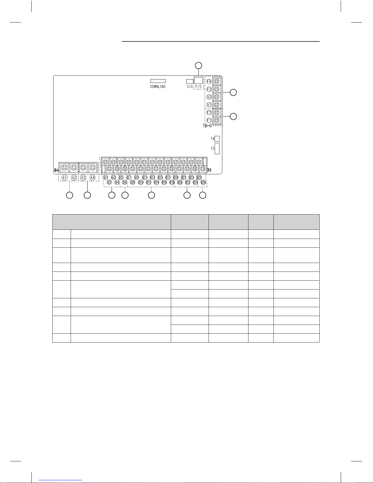
Wiring works
J
H
I
F GEDCBA
Output
Description PORT No. Input/Output AC/DC
Maximum running
current
A
Main power supply A1, A2 Input AC 30A
B Booster heater A3, A4 Output AC 20A
C
Backup heater & boiler (relay or magnetic
contactor control)
B1, B2, B3, B4 Output AC 0.5A
D Water pump B5, B6 Output AC 2A
E 2way valve B7~B18 Output AC 0.5A
F Room thermostat
B19, B20 Output AC 0.5A
B21~B24 Input AC 10mA
G Solar pump B25, B26 Input AC 10mA
H Communication line (RS485) F1, F2 Input/Output DC 10mA
I Wired remote controller
V1, V2 Output DC 210mA (per 1unit)
F1, F2 Input/Output DC 10mA
J Flow switch F/S Input DC 1mA
EHS Control unit_MIM-E03@_IM_E_34413-2.indd 8 2012-04-05 오후 1:19:57
9
ENGLISH
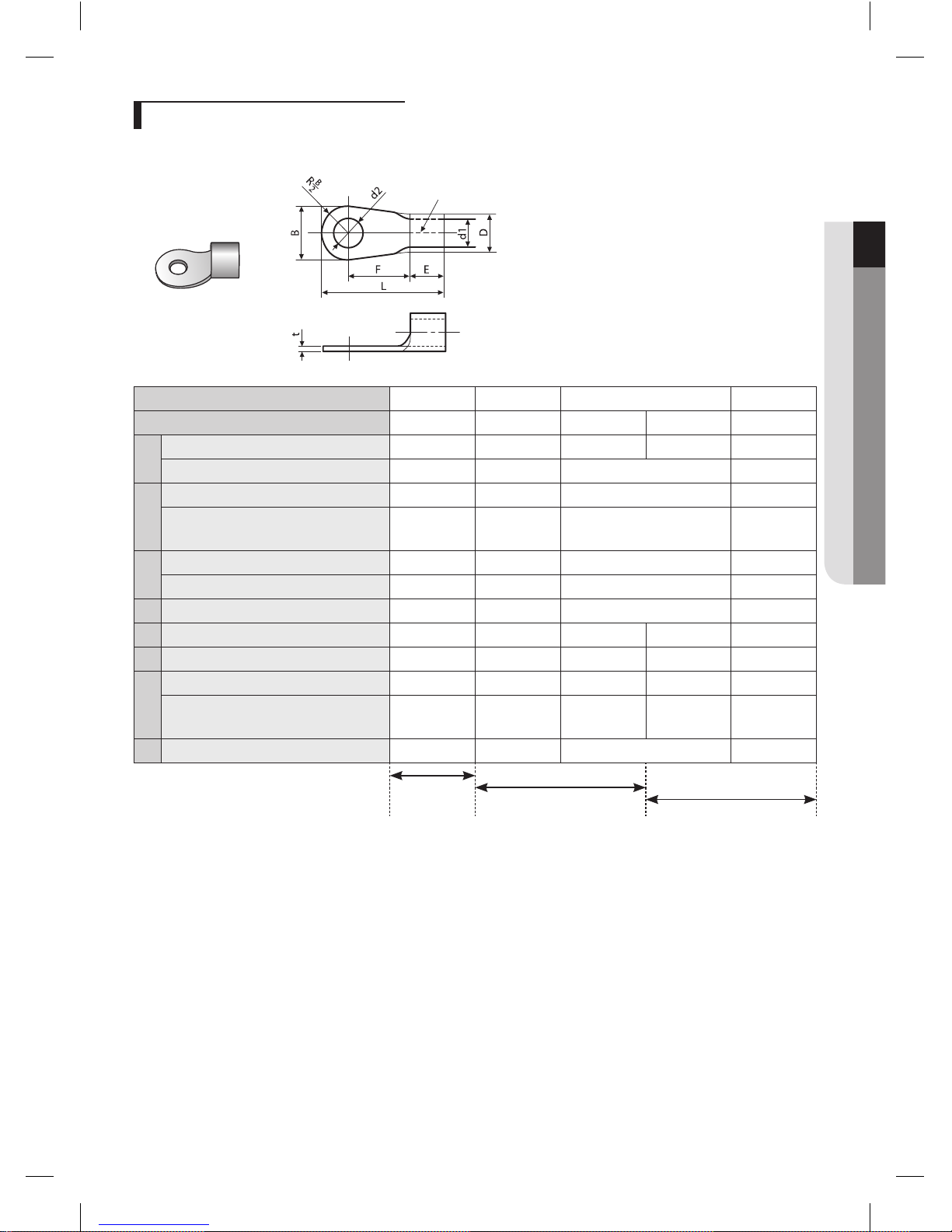
Selecting solderless ring terminal
Select a solderless ring terminal of a connecting power cable based on a nominal dimensions for cable.
Cover a solderless ring terminal and a connector part of the power cable and then connect it.
Silver solder
Nominal dimensions for cable (mm) 1.5 2.5 4/6 10
Nominal dimensions for screw (mm) 4 4 4 8 8
B
Standard dimension (mm) 8 9.5 9.5 12 12
Allowance (mm) ±0.2 ±0.2 ±0.2 ±0.2
D
Standard dimension (mm) 3.4 4.2 5.6 7.1
Allowance (mm)
+0.3
-0.2
+0.3
-0.2
+0.3
-0.2
+0.3
-0.2
d1
Standard dimension (mm) 1.7 2.3 3.4 4.5
Allowance (mm) ±0.2 ±0.2 ±0.2 ±0.2
E Min. 4.1 4.1 6 7.9
F Min. 6 7 5 9 9
L Max. 16 17.5 20 28.5 30
d2
Standard dimension (mm) 4.3 5.3 4.3 8.4 8.4
Allowance (mm)
+ 0.2
0
+ 0.2
0
+ 0.2
0
+0.4
0
+0.4
0
t Min. 0.7 0.8 0.9 1.15
M3
M4
M5
EHS Control unit_MIM-E03@_IM_E_34413-2.indd 9 2012-04-05 오후 1:19:57
10
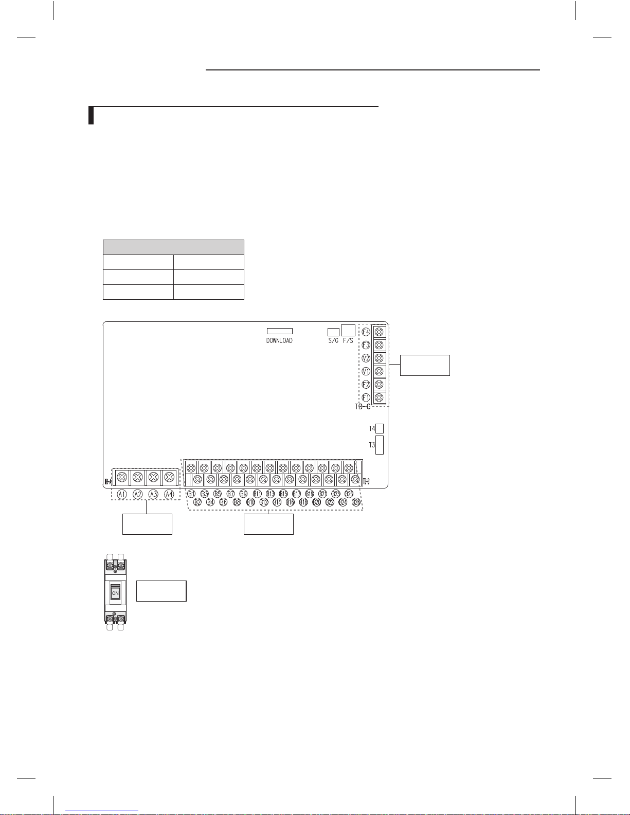
Wiring works
Selection for the power and booster heater wire terminal
Connect the cables to the terminal board using the solderless ring terminal.
Use certified and verified cables.
Connect using a driver which is able to apply the rated torque to the screws.
If the terminal is loose, fire may occur caused by arc.
If the terminal is connected too firmly, the terminal may be damaged.
External force should not be applied to the terminal block and wires.
The cable ties to fasten the wire should be an incombustible material, V0 or above.
(The cable ties should be used to fasten the power wire and they are supplied with the unit.)
Tightening Torque(kgf•cm)
M3.5 8 ~ 10
M4 12 ~ 15
M5 20 ~ 25
Main PCB
M4 Screw M3.5 Screw
M3.5 Screw
ELCB
M5 Screw
EHS Control unit_MIM-E03@_IM_E_34413-2.indd 10 2012-04-05 오후 1:19:58
11
ENGLISH
Grounding work
Grounding must be done by a qualified installer for your safety.
Grounding the power cable
The standard of grounding may vary according to the rated voltage and installation place of the air conditioner.
Ground the power cable according to the following.
Installation place
Power condition
High humidity Average humidity Low humidity
Electrical potential of lower than 150V
Perform the grounding work
3.
Note 1)
Perform the grounding work 2
if possible for your safety.
Note 2)
Electrical potential of higher than
150V
Must perform the grounding work 3.
Note 1)
(In case of installing circuit breaker)
Note 1) Grounding work 3
• Grounding must be done by your installation specialist.
• Check if the grounding resistance is lower than 100Ω. When installing a circuit breaker that can cut the electric circuit in
case of a short circuit, the allowable grounding resistance can be 30~500Ω.
Note 2) Grounding at dry place
• The grounding resistance is should be lower than 100Ω. (It should not be higher than 250Ω)
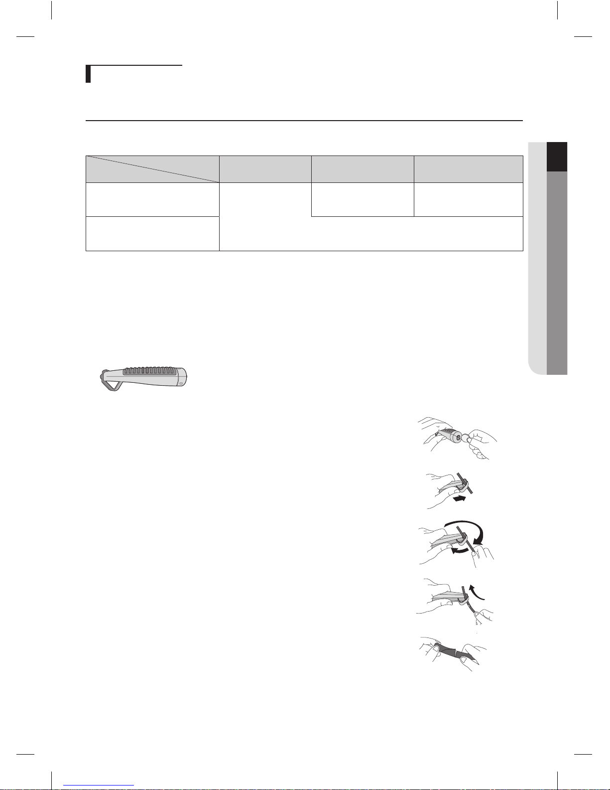
Examples to use cable striper
<Cable striper>
1. Adjust the blade position by coin(the controller is at the bottom side of the tool). Fix the
blade position according to the outer sheath thickness of the power cable.
2. Fix the power cable and tool by using the hook at the top side of the tool.
3. Cut out the outer sheath of the power cable by revolving the tool in the direction of the
arrow, two or three times.
4. At this situation, cut out the outer sheath of the power cable by moving the tool toward
the arrow direction expressed.
5. Slightly bend the wire and pull out the cut part of the outer sheath.
EHS Control unit_MIM-E03@_IM_E_34413-2.indd 11 2012-04-05 오후 1:19:58
 Loading...