

Samsung AE050JXYDEH, AE090JXYDEH, AE050JXYDEU, AE090JXYDEU, MIM-E03BN Service Manual
...
ECO HEATING SYSTEM CONTENTS
ECO HEATING SYSTEM
OUTDOOR UNIT
CONTROL KIT
1. Precautions
2. Product Specifications
3. Disassembly and Reassembly
4. Troubleshooting
5. PCB Diagram
6. Wiring Diagram
7. Reference Sheet
Model :
AE050JXYDEH/EU MIM-E03BN
Basic Model :
MIM-E03BN
AE090JXYDEH/EU MIM-E03AN
AE050JXYDEH/EU

Contents
1. Precautions ..............................................................................................................................................3
1-1 Precautions for the Service ..........................................................................................................................................3
1-2 Precautions related to static electricity and PL ...................................................................................................3
1-3 Precautions for the Safety ............................................................................................................................................4
1-4 Precautions for handling a system containing refrigerants .........................................................................5
1-5 Precautions for the brazing .........................................................................................................................................5
1-6 Precautions for charging refrigerants .....................................................................................................................5
2. General Overview ................................................................................................................................6
2-1 Features of the System ..................................................................................................................................................6
2-1-1 Key features of the Monobloc ..........................................................................................................................7
2-2 Product Specications ...................................................................................................................................................8
2-2-1 MONO Unit ...............................................................................................................................................................8
2-3 Specications of optional items ................................................................................................................................9
2-3-1 Accessories ................................................................................................................................................................9
3. Disassembly and Reassembly ......................................................................................................................... 11
3-1 EHS Control Kit ...............................................................................................................................................................12
3-2 Outdoor Unit ...................................................................................................................................................................14
4. Troubleshooting............................................................................................................................................................. 23
4-1 Wired remote controller .............................................................................................................................................23
4-2 Troubleshooting by symptoms ..............................................................................................................................26
4-2-1 Communication error after nishing Tracking ......................................................................................26
4-3 Control Kit ........................................................................................................................................................................ 27
4-3-1 EEPROM error .....................................................................................................................................................27
4-3-2
:
Error due to abnormal data of Wired remote controller thermistor value
............................28
4-3-3
: Error due to abnormal data of Water outlet thermistor value ..............................29
4-3-4
: Error due to abnormal data of DHW tank thermistor value ................................... 30
4-3-5 Control Kit temperature sensor(open/short) ........................................................................................31
4-3-6 Communication error after nishing Tracking(Hydro unit) ............................................................32
4-4 Items to check before diagnostics .......................................................................................................................33
4-4-1 Test run mode and view mode ....................................................................................................................33
4-4-2 Troubleshooting for outdoor unit ..............................................................................................................34
4-5 Troubleshooting by symptoms .............................................................................................................................36
4-5-1 Communication error after nishing tracking (E202) ........................................................... 36
4-5-2 Time out (1min.) of communication error between MAIN PBA and INV. PBA (E203)
............ 37

Contents
4-5-3 Temperature sensor error (E221, E231, E251, E320 )
...................................................................... 38
4-5-4 Fan error (E458, E475)
............................................................................................................................. 39
4-5-5 Compressor error (E461, E467) .......................................................................................................41
4-5-6 Current trip error (E462, E463) ........................................................................................................ 42
4-5-7 IPM(IGBT module) over current error (E464) ............................................................................ 43
4-5-8 DC-link voltage under/over error (E466) .................................................................................... 45
4-5-9 GAS leak error(E554) ........................................................................................................................... 46
4-5-10 The other errors .................................................................................................................................. 47
4-5-11 In case of heating at the cooling mode or coolin g at the heating mode .................. 48
4-5-12 Outdoor unit is not powered on – Initial diagnosis ............................................................. 50
4-5-13 Outdoor unit power supply error ............................................................................................... 51
5. PCB Diagram
....................................................................................................................................................................
52
5-1 Control Kit......................................................................................................................................................... 52
5-2 Outdoor Unit ................................................................................................................................................... 54
6. Wiring Diagram ................................................................................................................ 57
6-1 Control Kit......................................................................................................................................................... 57
6-2 Outdoor Unit ................................................................................................................................................... 58
7. Reference Sheet ............................................................................................................... 59
7-1 Index for Model Name................................................................................................................................. 59
7-1-1 Outdoor Unit ......................................................................................................................................... 59
7-2 Refrigerant Circuit Diagram ...................................................................................................................... 60
7-3 FSV data check and update using S-Net Pro2 ...................................................................................61
7-4 EHS FSV Values Import and Export .........................................................................................................62

Samsung Electronics 3
1. Precautions
1-1 Precautions for the Service
Use the standard parts when replacing the electric parts.
– Confirm the model name, rated voltage, rated current of the electric parts.
When repairing the equipment, connection of the harness parts must be firm and solid.
– A loose connection may cause noise or other malfunction.
When assembling and disassembling the equipment while it is laid down, lay it on soft cloth.
– Otherwise it may scratch the back of the exterior of the product.
Remove dust or dirt completely from the housing block, wiring block and service parts during repair.
– This helps prevent the danger of fire caused by tracking or short circuit.
Fasten the valve caps of service valves and charging valves of outdoor unit as much as possible using adjustable wrenches.
Check the status of the components’ assembly after repair service.
– The status must be the same as before the repair service.
1-2 Precautions related to static electricity and PL
The PCB power supply block is susceptible to static electricity. Therefore, care must be taken during repair or measuring
while the power is on.
– Wear insulation gloves for PCB repair or measuring.
Check whether the installation location is at least two meters away from other electronic products such as TV, video, or
audio.
– Otherwise, the video quality might be degraded or noise might be generated.
Do not let end users repair the products themselves.
– Unauthorized disassembly might cause electric shock or fire.

Precautions
4 Samsung Electronics
1-3 Precautions for the Safety
Do not pull any electric wires and do not touch an auxiliary power switch with a wet hand.
– There is a danger of electric shock or fire.
In case any wire or power plug has been damaged, replace it to eliminate any possible danger.
Do not bend the power cord by force and do not put any heavy object on the power cord.
– There is a danger of electric shock or fire.
Do not use multi socket.
– There is a danger of electric shock or fire.
Ground the product if necessary.
– Be sure to ground the product if there is any danger of electric leakage due to water or moisture.
Be sure to turn off the auxiliary power switch or pull out the power plug during replacement or repair of electric parts.
– There is a danger of electric shock.
In case the product will not be in use for a long time, the battery of remote control should be kept separately.
– Leakage of inside fluid can cause break down of remote control.
The installation must be done by the manufacturer or its service agent or a similar qualified person in order to avoid a hazard.
– Installation by an unqualified person may cause a water leakage, electric shock or fire and so on.
The electric work must be done by service agent or similarly qualified persons according to national wiring regulations and use
only rated cable.
– If the capacity of the power cable is insufficient or electric work is not properly completed, electric shock or fire may occur.
Use only rated parts and tools.
– If you don't use the rated parts and tools, it can cause trouble with the air conditioner and bring about injury.
If any gas or impurities except R410A refrigerant come into the refrigerant pipe, serious problem may occur and it may cause
injury.
Leak test must be done using only Nitrogen(NO2)gas.
R410A refrigerant is used for EHS.
– When using R410A, moisture or foreign substances may affect to the capacity and reliability of the product.Safety precautions
must be taken when installing the refrigerant pipe.
– The design pressure of the unit is 4.1MPa. Select appropriate material and thickness according to the regulations.
– R410A is a quasi-azeotrope of two refrigerants.
Make sure to charge liquid one when adding refrigerant.
If you charge gaseous refrigerant, it may affect the capacity and reliability of the product as a result of change formation of the
refrigerant.

Precautions
Samsung Electronics 5
1-4 Precautions for handling a system containing refrigerants
All system containing refrigerants shall be removed under regional regulations prior to the disposal to
prevent the potential health and environmental consequences.
Harmful for human body
– When emitted liquid refrigerant contacts human body, contacted area may get frostbite, blister or become numb.
If refrigerant leaks in airtight area, lack of oxygen may cause suffocation. When refrigerant is heated, it may generate harmful gas.
Precautions for handling container
– Do not apply shock or heat to the refrigerant container.
1-5 Precautions for the brazing
Clear any dangerous or inflammable materials in surrounding environment.
Make sure to empty the remaining refrigerant in the product or pipe before brazing.
– Brazing with the refrigerant still remaining in the product or pipe may cause poor result and generate harmful gas. Furthermore,
pressure of the refrigerant may increase and cause damage to the leaking part. This may lead harmful refrigerant and oil to spurt
out which can be dangerous for service personnel.
Use nitrogen gas to get rid of the oxide forming during brazing.
– Using other type of gas may cause damage to the product or the exterior.
1-6 Precautions for charging refrigerants
Add quantity of the refrigerant using a scale and perform a test operation with S-net.
– Product performance may decrease if you add excessive amount of refrigerant.
Do not charge refrigerants while heating the container up.
– The container may get damaged by the heat and result in explosions.
Do not operate the product without pressure switch(for product protection) and sensor.
– If there are any internal blockage, high refrigerant pressure increase may damage the product or exterior.
6 Samsung Electronics
2. General Overview
2-1 Features of the System
POWER SAVING
EHS(Eco Heating System) considers the trend in air conditioner use. It optimizes the
energy efficiency of loads ranging from partial to full. It achieves an excellent energy
effect for the users of the air conditioner.
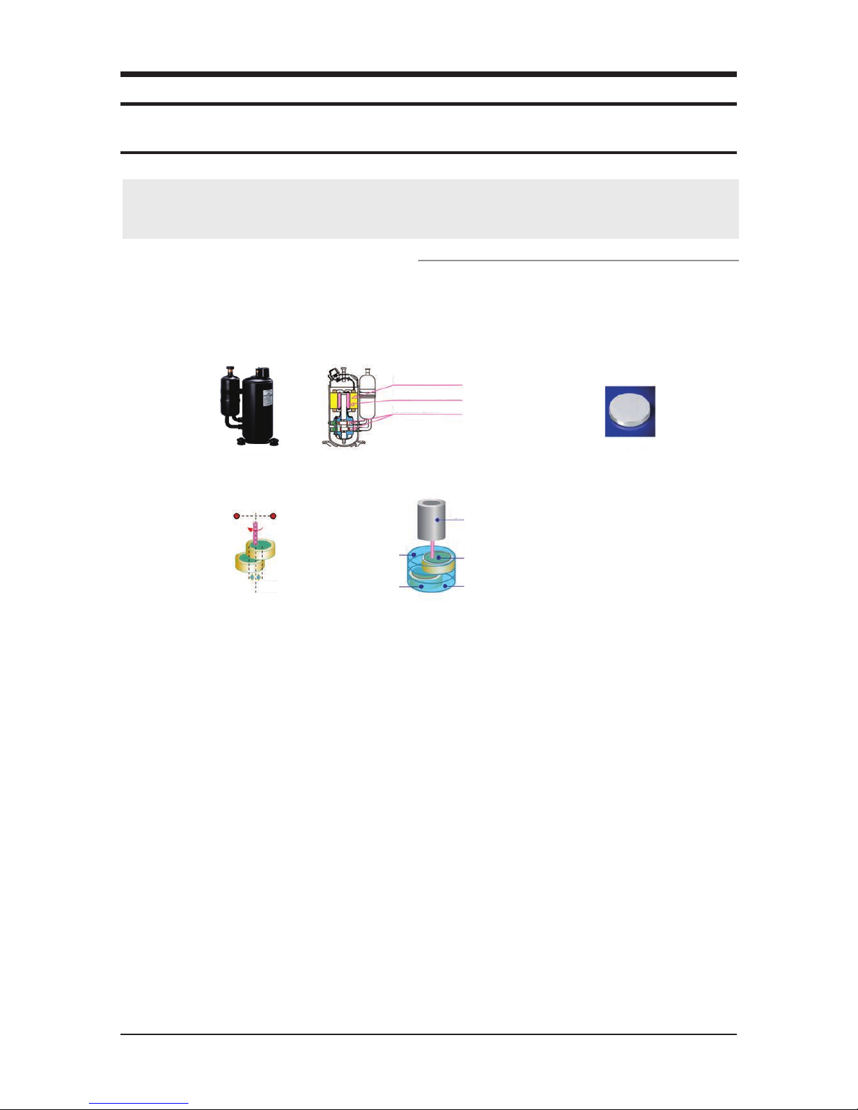
Samsung patented compressor
Samsung has been researching and developing compressors since the 70's.
It has developed power saving compressors for more than thirty years.
The EHS(Eco Heating System) compressor adopts a double-rotor BLDC compressor with permanent magnets made by Samsung.
Electricity for the compressor rotor is obtained from a neodium-iron-boron permanent magnetic material (boron magnet can attract iron
material weighing 1000 times its own weight.) It strengthens the rotary moment of the compressor to maximize the entire efficiency of the
compressor.
BLDC electricity
Permanent magnet, strong magnetic rotor
Double rotor compression cylinder
Nd-Fe-B Neodium-Iron-Boron magnet
SAMSUNG's double-rotor compressor has the upper and lower rotors designed symmetrically.
The double rotor in symmetry can remove vibrations caused by the eccentric design of the cylinder.
2 rotors balancing the rotary moment
Centered symmetry
Upper rotor
Permanent magnet rotor
Lower cylinder
Upper cylinder
Lower rotor

General Overview
Samsung Electronics 7
2-1-1 Key features of the Monobloc
Easy installation
No need to install the refrigerant lines in the system. Users can run the system after connecting water pipes only.
Integrated Heating & Cooling system
Plate Heat exchanger is a integral part in heating & cooling system. For user’s convenience, PHE is integrated into the system.
This concept will help space saving and lower costs for pipe line reduction.
Running Costs-Reduction of Up to 32.4%
Samsung EHS, known for its world class efficiency (12kW floor heating system with COP of 4.51), can reduce 32.4% of your run-
ning costs as compared to a gas boiler.
High Performance at Low Temperature
Samsung EHS is made up of an inverter compressor optimally operated according to the outdoor temperature, offering heating
performance of 90% at -10°C and reliable frost protection at -25°C.
8 Samsung Electronics
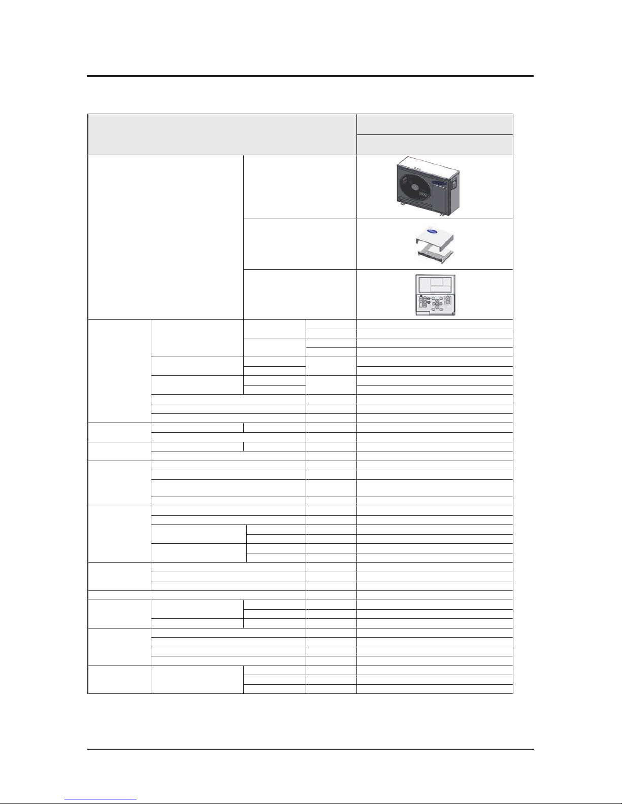
2-2 Product Specifications
2-2-1 MONO Unit
Item
AE050JXYDEH
1phase 5kW
Image
Outdoor unit
Control Kit
Remote Controller
A2W
Condition #1.
(A7/W35) *1
Nominal Capacity
Heating
W 5,000
Btu/h 17,100
Cooling
W 5,000
Btu/h 17,100
Power Input(Nominal)
Heating
W
1,0 60
Cooling 1,210
Current Input(Nominal)
Heating
A
5.1
Cooling 5.7
COP (Nominal He ating) W/W 4.72
EER (Nominal Co oling) W/W 4 .13
SCOP A+++
A2/ W35
Capacity Heating W 4,500
COP W/W 3.46
A-7/ W35
Capacity Heating W 4,700
COP W/W 2.69
Field
Wiring
MCA A 20
MFA A 25
Power Source Wire
㎡
L<10 m, 2. 5↑
10m<L<20m, 4.0↑
Transmission Cable
㎡
0.75↑
Water
Connections
Water Flow Rate (Heating/Cooling) LPM 14. 5/14.5
Water Pressure (Max) bar 3
Water Pipe
Inlet Φ, in ch BSPP male 1"
Outlet Φ, in ch BSPP male 1"
Leaving Water Temperature
Heating °C 25~55
Cooling °C 5 ~25
Refrigerant
Typ e - R410 A
Control Method - EEV
Factory Charging g 1,150
Power Supply Φ, #, V, Hz E(220~240V, 50Hz, 1Ф)
Sound *3
Sound
Pressure
Heating Std High dB(A) 45
Cooling Std High dB(A) 45
Sound Power Heating Std High dB 61
External
Dimension
Net Weight kg 59
Shipping Weight kg 63
Net Dimensions (WxHxD) mm 880 x 798 x 310
Shipping Dimensions (WxHxD) mm 1,023 x 904 x 413
Operating
Temp. Range
A2W
Heating
℃
-25~35
Cooling
℃
10~ 46
D.Hot Water
℃
-25~ 43
*1) A2W Condition #1 : (Heating) Water I n/Out 30℃/35℃, Outdoor Air 7℃D B/6℃WB; (Cooling) Water In/Out 23℃/18℃, Outdoor Air 35℃DB.
*2) Sound pressu re was acquired in an anecho ic room. Thus actual noise level may be dif ferent depending on the installation conditions.
Samsung Electronics 9
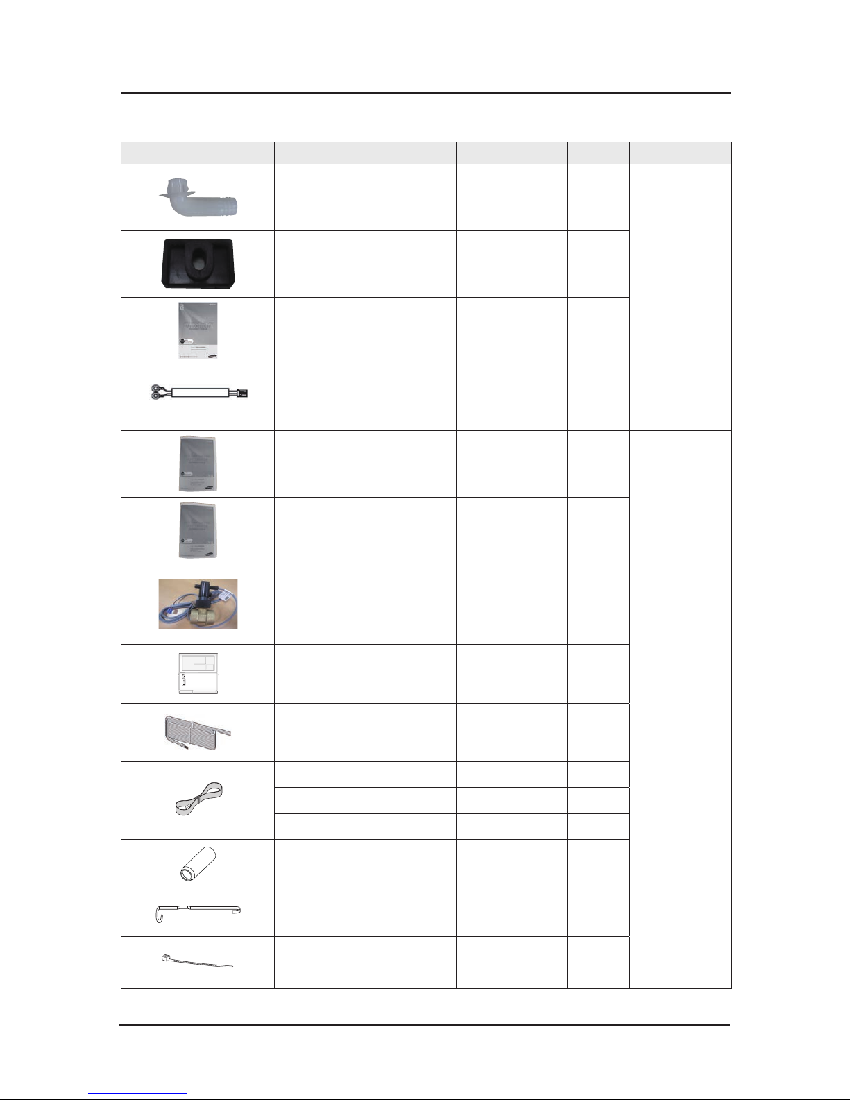
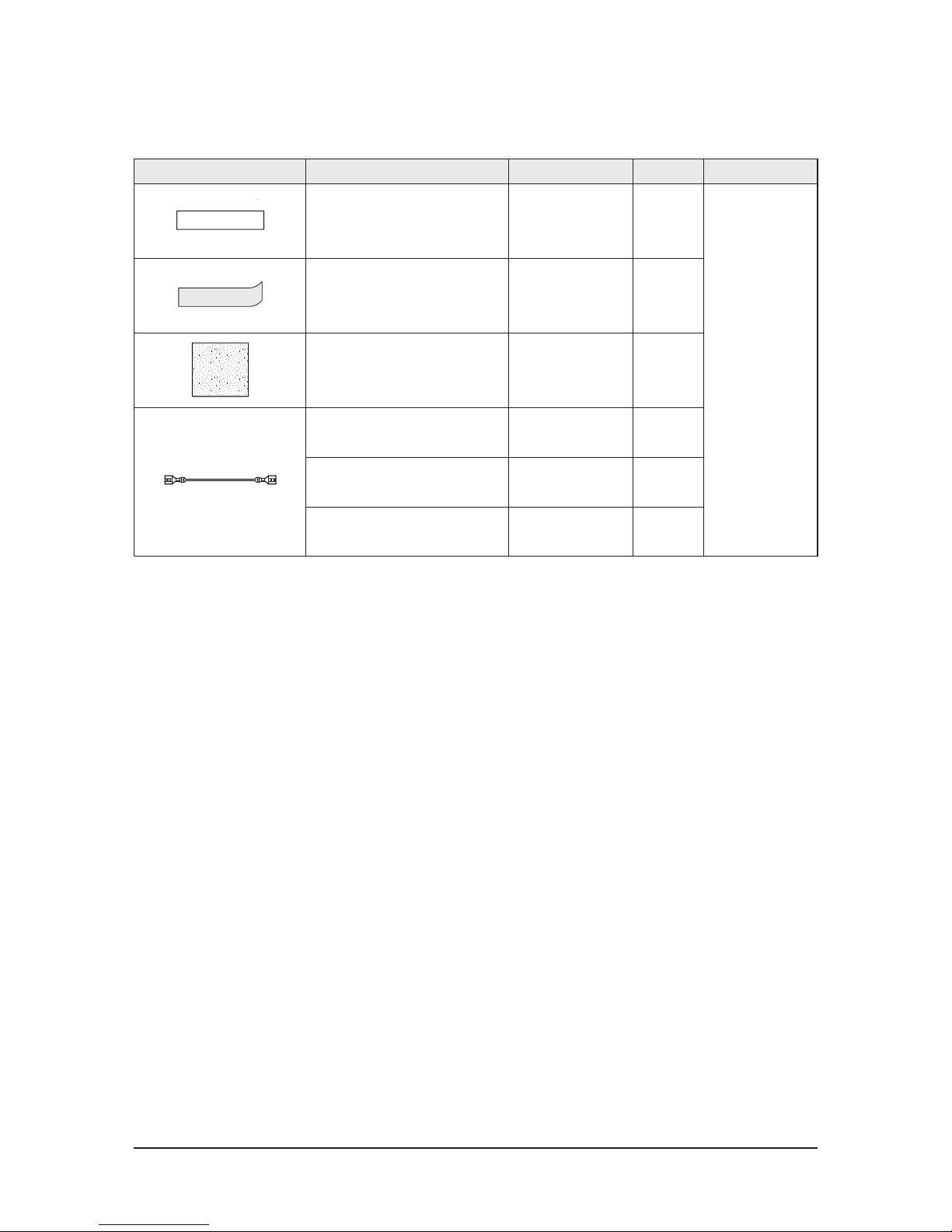
Item Description Code No. Q’ty Remark
Drain Plug DB6 7-20 011A 1
Essential Offer
(Outdoor Unit)
Rubber Leg DB73-20134A 4
MANUAL INSTALL (Outdoor Unit) DB 68-0 5133A 1
Assy Connector Wire
(Wire for Silent mode)
DB93-08678A
1
MANUAL USERS (CONTROL KIT) DB68-05402A 1
Essential Offer
(Control Kit)
MANUAL INSTALL (CONTROL KIT) DB68-05388A 1
Switch-Flow DB34-00084A 1
Wired remote controller DB9 3-1125 1L 1
Connector Wire
(Smart Grid, 2000mm)
DB 93 -13255A 1
SENSOR TEMP DB 32- 00213A 1
Thermistor (Water Tank) DB95-05023A 1
SENSOR TEMP DB32- 00217A 1
HOLDER SENSOR DB 61- 05217A 2
SPRING ETC-SENSOR DB81-00635A 2
CABLE TIE DB 65-100 88C 4
2-3 Specifications of optional items
2-3-1 Accessories
10 Samsung Electronics
Accessories
Item Description Code No. Q’ty Remark
TAPE-HANDLE CABI SIDE DB74-00039D 2
Essential Offer
(Control Kit)
RUBBER-PIPE DB73-00436B 2
INSULATION-BASE DB72-00 401F 2
ASSY CONNECTOR WIRE-CLIP
(Back-up heater connector(Brown))
DB93-08924R 1
LEAD CONNECTOR
(Back-up heater connector (Red))
DB39-0 0941A 1
LEAD CONNECTOR
(Back-up heater connector(White))
DB39-0 0941B 1
Samsung Electronics 11
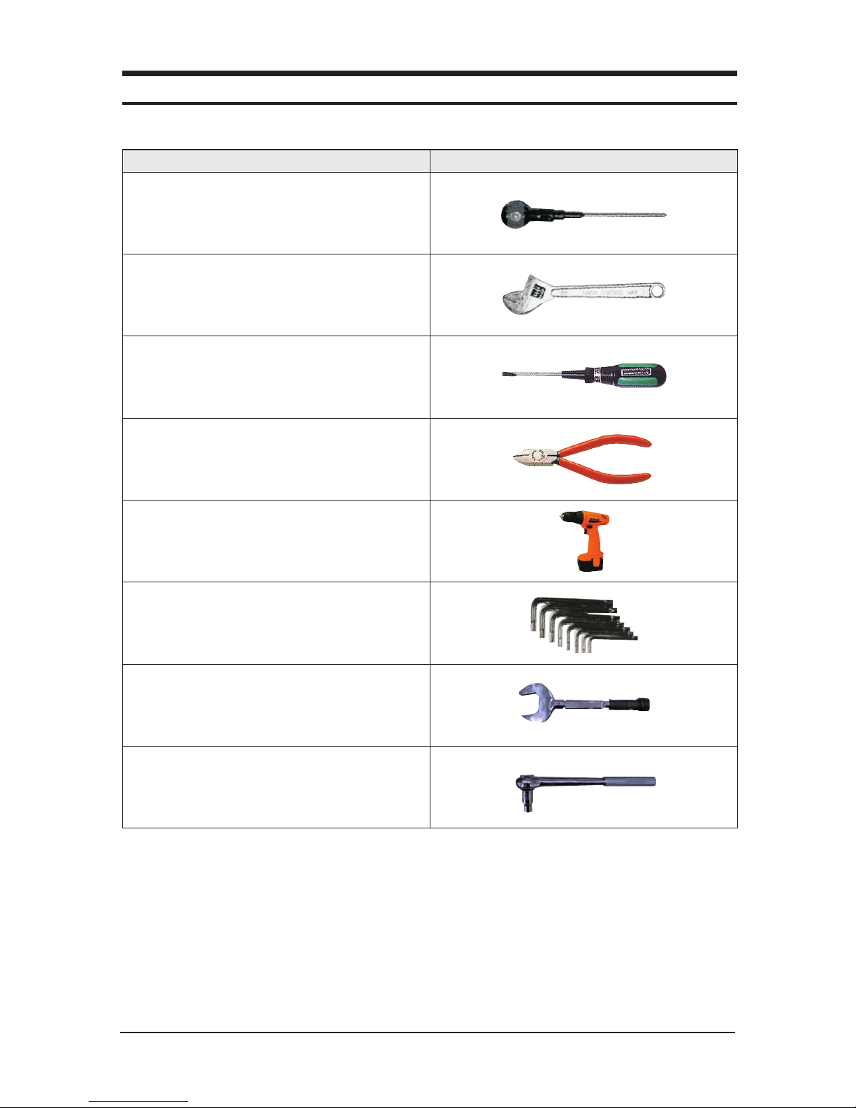
Hand Tool sets
3. Disassembly and Reassembly
Item Remark
+Screw Driver
Adjustable wrench
–Screw Driver
Nipper
Electric Motion Driver
L-Wrench
Torque Lench
Latchet Lench

12 Samsung Electronics
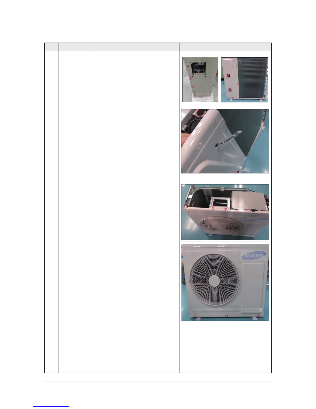
No Parts Procedure Remark
1 CABINET TOP
You must turn off the power before
disassembling.
1) Unscrew and remove the two screws
on the CABINET TOP.
(Use '+' type screw driver)
2) Remove the CABINET TOP.
2 ELCB 1) Unscrew and remove the two screws of the
power supply cable on the terminal block.
(Use '+' type screw driver)
2) Unscrew and remove the two screws on the
top & bottom of the ELCB.
(Use '+' type screw driver)
3-1 EHS Control Kit
Be sure that the power switch is in the OFF and the power source cord shall be unplugged prior to disassembly and reassembly works.
Disassembly and Reassembly
Samsung Electronics 13
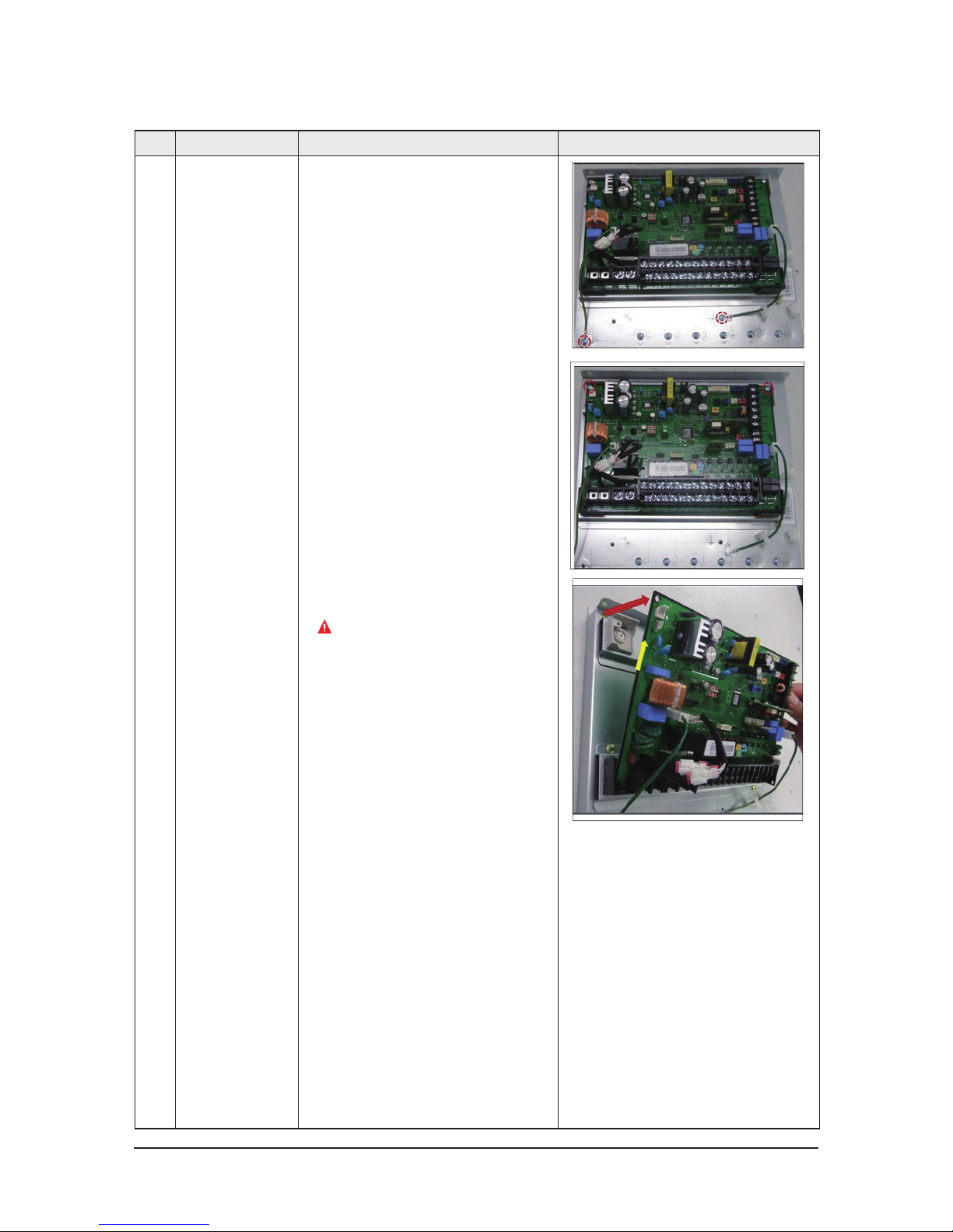
No Parts Procedure Remark
3 ASSY PCB MAIN OUT 1) Unscrew and remove the earth screw
on the CABINET BOTTOM.
(Use '+' type screw driver)
2) Unscrew and remove the two screws.
(Use ‘+’type screw driver)
3) Firstly pull the PCB along red arrow ,then pull
the PCB out along yellow arrow.
Please note that PCB support may be
broken by your excessive pulling.
14 Samsung Electronics
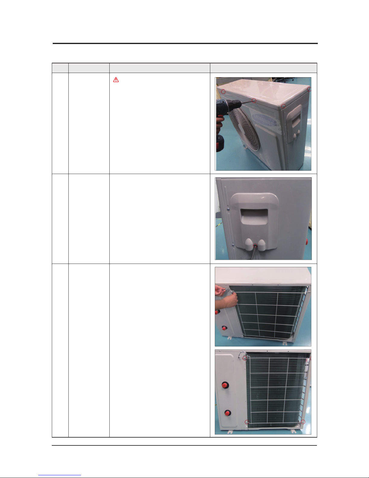
No Parts Procedure Remark
1 CABI TOP
You must turn off the power before
disassembling.
1) Unscrew and remove the ten screws on each
side of the CABI TOP.
(Use '+' type screw driver)
2 ASSY COVER
CONTROL
1) Unscrew and remove the one screw
on the ASSY COVER CONTROL.
(Use '+' type screw driver)
3 GUARD COND 1) Pull the sensor from Guard Cond.
2) Unscrew and remove the four screws
on the GUARD COND.
(Use ‘+’type screw driver)
AE050JXYDEH
3-2 Outdoor Unit
Disassembly and Reassembly
Samsung Electronics 15
No Parts Procedure Remark
4 CABI SIDE RH 1) Unscrew and remove the eleven screws
on each side of the CABI BACK RH.
(Use '+' type screw driver)
2) Pull the sensor from the CABI SIDE RH.
5 CABI FRONT 1) Unscrew and remove the 9 screws
on the CABI FRONT.
(Use '+' type screw driver)

Disassembly and Reassembly
16 Samsung Electronics
No Parts Procedure Remark
5 CABI FRONT 1) Unscrew and remove the 9 screws on each side
the CABI FRONT.
(Use '+' type screw driver)
6 FAN 1) Turn the one nut as shown in the picture and
remove it.
(Use adjustable wrench)
Disassembly and Reassembly
Samsung Electronics 17
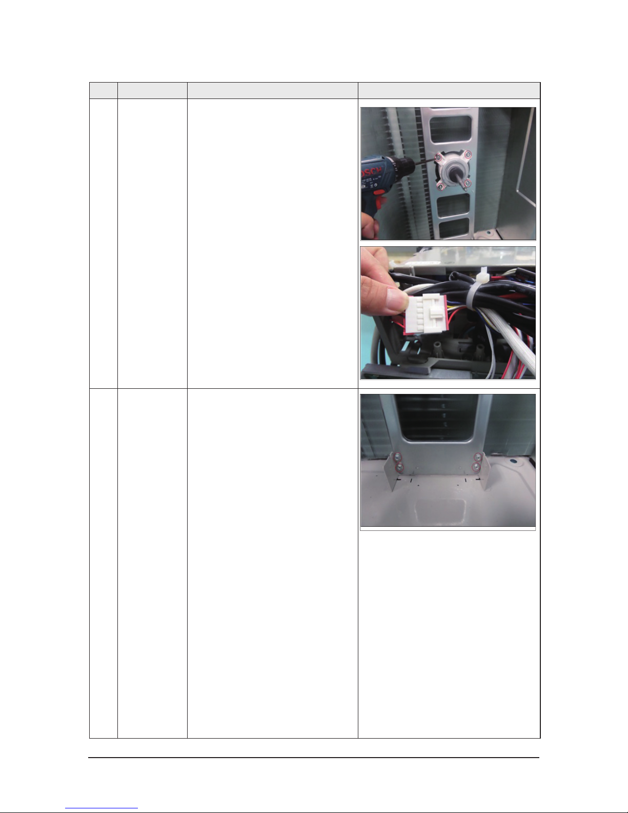
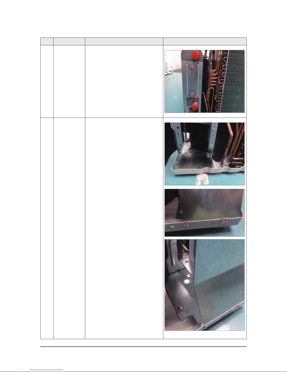
No Parts Procedure Remark
7 MOTOR 1) Remove the fan.
2) Unscrew and remove the four motor screws.
(Use '+' type screw driver)
3) Disconnect the motor wire from the Ass'y
Control Out.
8 BRACKET 1) Unscrew and remove the two screws on the
BRACKET MOTOR.
(Use '+' type screw driver)
Disassembly and Reassembly
18 Samsung Electronics
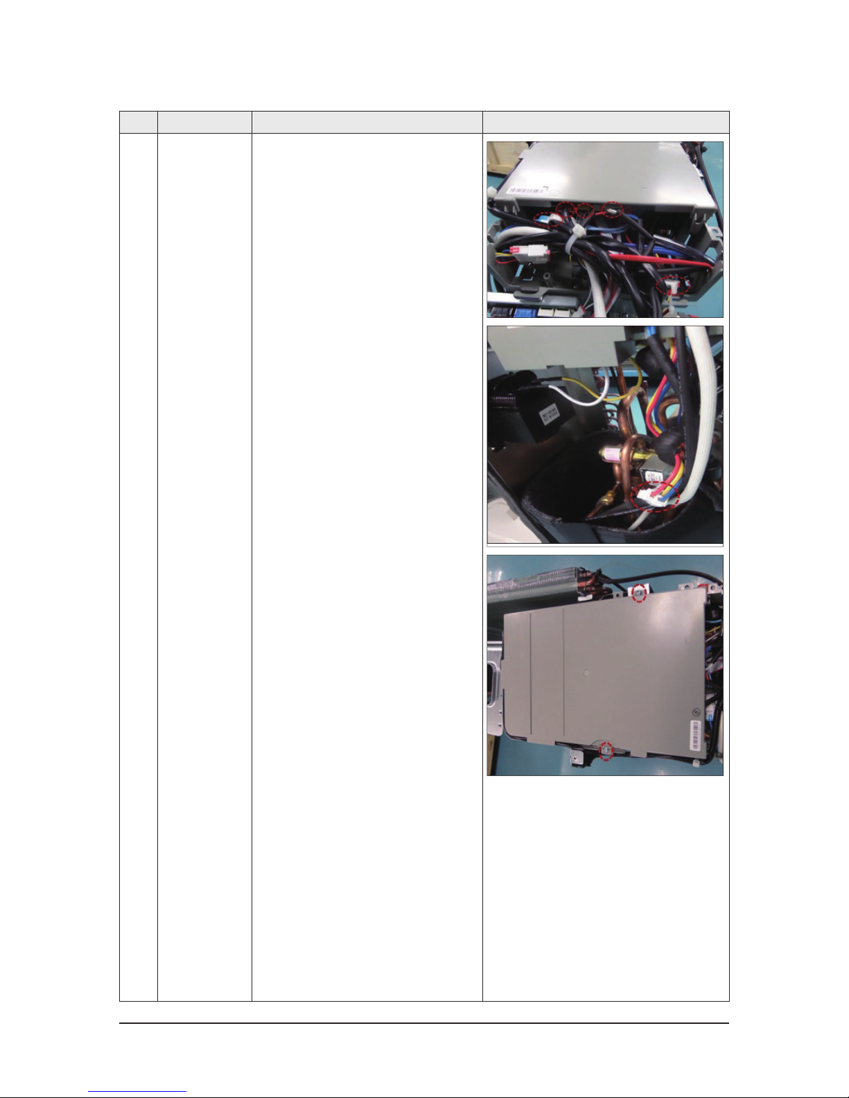
No Parts Procedure Remark
9 CONTROL OUT 1) Disconnect the six connectors from the ASSY
CONTROL OUT.
2) Unscrew and remove the two screws on the
CONTROL OUT.
(Use '+' type screw driver)
3) Separate the ASSY CONTROL OUT
Disassembly and Reassembly
Samsung Electronics 19
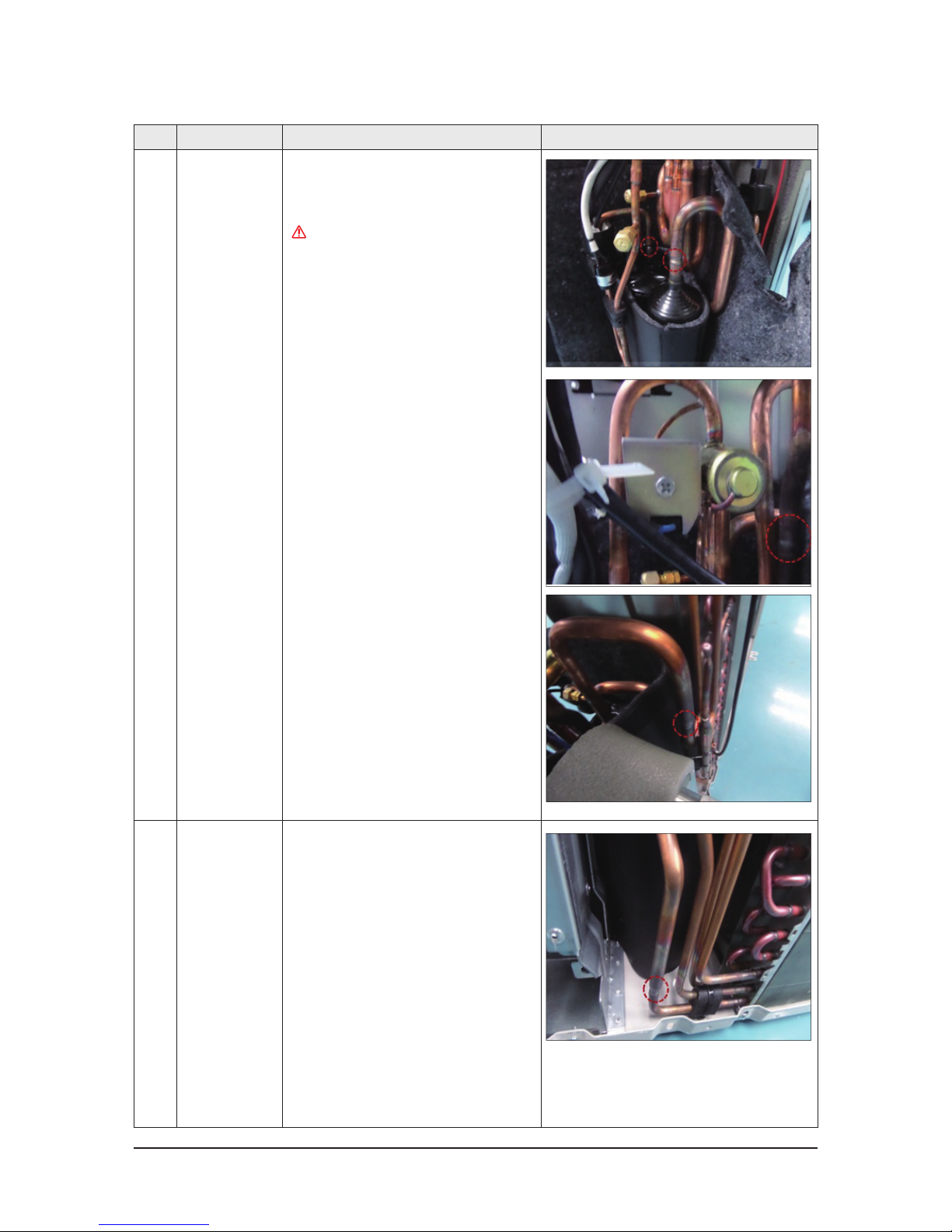
No Parts Procedure Remark
10 ASSY-VALVE 4WAY 1) Purge the coolant first.
2) Separate the pipe from the Entrance/Exit using
a welder.
When removing the compressor,heat
exchanger and pipe, purge the completely
and remove the pipe with a welding flame.
11 ASSY TUBE-WATER 1) Purge the coolant first.
Disassembly and Reassembly
20 Samsung Electronics
No Parts Procedure Remark
2) Turn the two nuts as shown in the picture and
remove them.
(Use adjustable wrench)
12
ASSY BRACKET PHE
1) Unscrew and remove the 4 screws on the ASSY
BRACKET PHE.
(Use '+' type screw driver)
 Loading...