

Samsung MIM-E03A Installation Manual
"EEE Yönetmeliğine Uygundur"
"This EEE is compliant with RoHS"
MIM-E03✴
SAMSUNG CONTROL UNIT
installation manual
imagine the possibilities
Thank you for purchasing this Samsung product.
To rece ive more comple te service, please
register your product at
www.samsung.com/register
E S F I P D
DB98-00000A(1)
2 3
ENGLISH
Safety precautions
Carefully follow the precautions listed as below because they are essential to guarantee the safety of SAMSUNG product.
WARNING
• Always disconnect a power supply of Air-Water Heat Pump before servicing it or accessing
components inside the unit.
• Verify that installation and testing operations shall be performed by qualified personnel.
• To prevent serious damage on the system and injuries to users, precautions and other
notices shall be observed.
Warning
Carefully read the contents of this manual before installing the control kit and store the manual in a safe place in order to
be able to use it as reference after installation.
For maximum safety, installers should always carefully read the following warnings.
Store the manual in a safe location and remember to hand it over to the new owner if the kit is sold or transferred.
The kit is compliant with the requirements of the Low Voltage Directive (72/23/EEC), the EMC Directive (89/336/EEC) and
the Directive on pressurized equipment (97/23/EEC).
The manufacturer shall not be responsible for damage originating from unauthorized changes or the improper
connection of electric and hydraulic lines. Failure to comply with these instructions or to comply with the requirements
set forth in the “Operating limits” table, included in the manual, shall immediately invalidate the warranty.
Do not use the units if you see some damages on the units and recognize something bad such as loud noisy, smell of
burning.
In order to prevent electric shocks, fires or injuries, always stop the unit, disable the protection switch and contact
SAMSUNG’s technical support if the unit produces smoke, if the power cable is hot or damaged or if the unit is very noisy.
Always remember to inspect the unit, electric connections, and protections regularly. These operations shall be
performed by qualified personnel only.
The unit contains various electric parts, which should be kept out of the reach of children.
Do not attempt to repair, move, alter or reinstall the unit by unauthorized personnel, these operations may cause product
damage, electric shocks and fires.
Do not place containers with liquids or other objects on the unit.
All the materials used for the manufacture and packaging of the air to water heat pump are recyclable.
The packing materials must be disposed of in accordance with local regulations.
Wear protective gloves to unpack, move, install, and service the unit to avoid your hands being injured by the edge of the
parts.
Do not touch the internal parts while running the units.
Inspect the product shipped and check if damaged during transport. If the product has some damages,
DO NOT INSTALL and immediately discuss about the damages with the carrier or retailer (if the installer or the authorized
technician has collected the material from the retailer.)
Our units shall be installed in compliance with the spaces described in the installation manual, to ensure accessibility
from both sides and allow repairs or maintenance operations to be carried out. If the units installed without complying
with procedures described in manual, additional expenses can be asked because special harnesses, ladders, scaffolding
or any other elevation system for repair service will NOT be considered part of the warranty and will be charged to the
end customer.
When service works required, make sure to disconnect the power supply at least 1 minute to prevent electric shocks.
- Always check the voltage at the terminals of main PCB before trying to touch.
Use electric wires which manual designated. Connections between wires and terminals shall be assembled without any
tension. If the assembly works is not implemented well, it can lead to have product damages and fires.
After wiring works, terminal block cover shall be fixed firmly. Without cover, it can cause to have product damage and fire.
Contents
Safety precautions . .. . . . .. . . . .. . . . .. . . . .. . . . .. . . .. . . . .. . . . .. . . . .. . . . .. . . . .. . . . .. . . . .. . . . .. . . . .. . . .. . . . .. . . . .. . . . .. . . . .. . . 3
Product specifications .. . . .. . . . .. . . . .. . . . .. . . . .. . . . .. . . . .. . . . .. . . . .. . . . .. . . .. . . . .. . . . .. . . . .. . . . .. . . . .. . . . .. . . . .. . . . .. . . . . 4
Main components .. . . . .. . . . .. . . . .. . . . .. . . .. . . . .. . . . .. . . . .. . . . .. . . . .. . . . .. . . . .. . . . .. . . . .. . . .. . . . .. . . . .. . . . .. . . . .. . . . .. . . . 4
Installing the unit . .. . . . .. . . . .. . . . .. . . . .. . . .. . . . .. . . . .. . . . .. . . . .. . . . .. . . . .. . . . .. . . . .. . . . .. . . .. . . . .. . . . .. . . . .. . . . .. . . . .. . . . 5
Wiring works . . . . .. . . . .. . . . .. . . . .. . . . .. . . . .. . . . .. . . . .. . . . .. . . .. . . . .. . . . .. . . . .. . . . .. . . . .. . . . .. . . . .. . . . .. . . . .. . . .. . . . .. . . . . 8
Setting option switches and function of keys .. . . . .. . . . .. . . . .. . . . .. . . . .. . . . .. . . . .. . . . .. . . . .. . . .. . . . .. . . . .. . . . .. . . . .. . . . .. 23
Test operation .. . . . .. . . . .. . . . .. . . .. . . . .. . . . .. . . . .. . . . .. . . . .. . . . .. . . . .. . . . .. . . . .. . . .. . . . .. . . . .. . . . .. . . . .. . . . .. . . . .. . . . .. . 27
Before running the system . .. . . . .. . . . .. . . . .. . . . .. . . . .. . . . .. . . . .. . . . .. . . . .. . . .. . . . .. . . . .. . . . .. . . . .. . . . .. . . . .. . . . .. . . . .. . . 29
Troubleshooting . .. . . . .. . . . .. . . . .. . . . .. . . . .. . . . .. . . . .. . . .. . . . .. . . . .. . . . .. . . . .. . . . .. . . . .. . . . .. . . . .. . . . .. . . .. . . . .. . . . .. . . . 30
Error codes .. . . . .. . . . .. . . . .. . . .. . . . .. . . . .. . . . .. . . . .. . . . .. . . . .. . . . .. . . . .. . . . .. . . .. . . . .. . . . .. . . . .. . . . .. . . . .. . . . .. . . . .. . . . . 31
4 5
ENGLISH
Installing the unit
Deciding on where to install the unit
Install the unit in indoor and do not install it outside. The unit is designed only for indoor.
Direct heat can make the kit have some failures in operation.
Choose locations that are dry and sunny, but not exposed to direct sunlight or strong winds.
Choose location where pipes and cables can be easily connected to the indoor unit.
Avoid locations where flammable elements and explosive chemicals are stored.
Choose a specific wall which can withstand the weight of unit and an outside force.
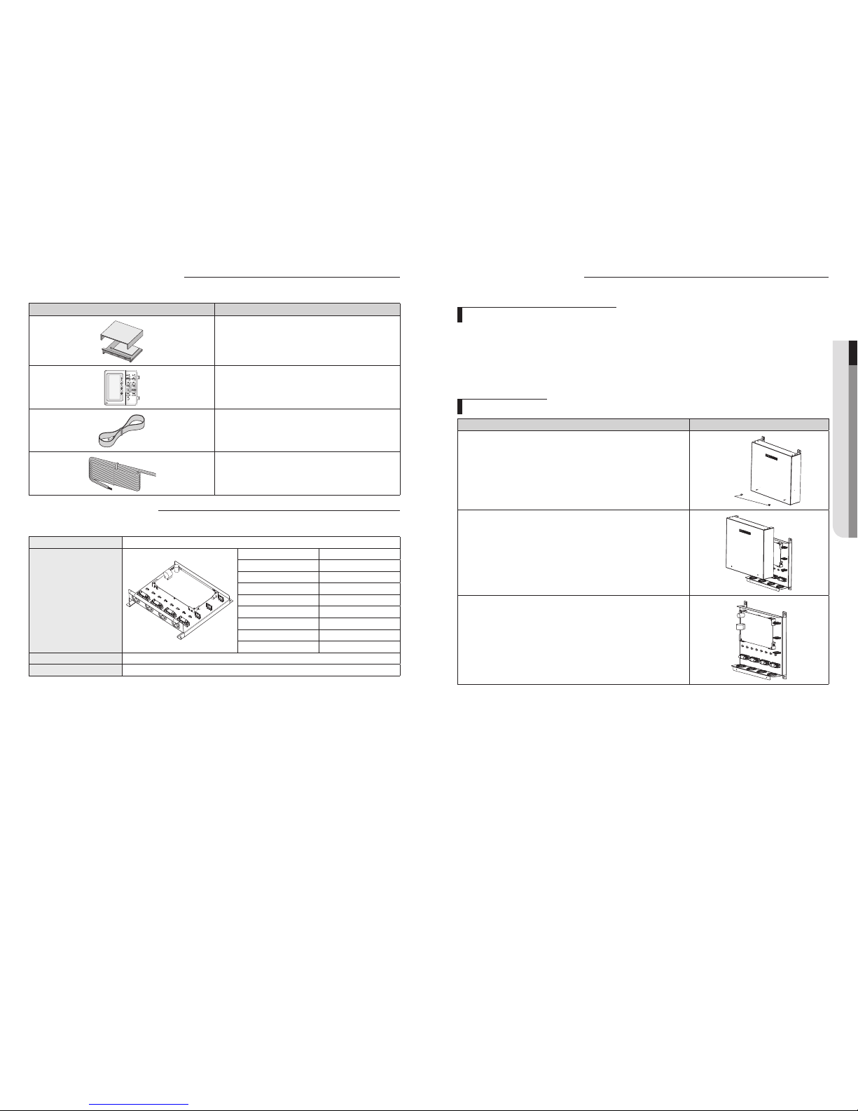
Mounting the unit
Procedure Remark
1. Remove 2 bolts from the unit.
Bolt
2. Open the top cover and install 4 screws on the wall.
3. Close the top cover and install 2 bolts again into the unit.
Product specifications
Item Description
MIM-E03A
Wired remote controller
Temperature sensor (Thermistor / 1EA)
Remote controller cable (1EA, 4core 15m)
Main components
Model name MIM-E03A
Detail components
Parts Qty.
Main PBA 1
Wire holder Total 7EA (2 type)
PCB support 4
Grounding screw 8
Rubber 4
Base plate 1
Top cover plate 1
Case screw 2
Weight (Net) 3kg
Packing size (W x H x D) 323 mm x 339 mm x 131 mm
6 7
ENGLISH
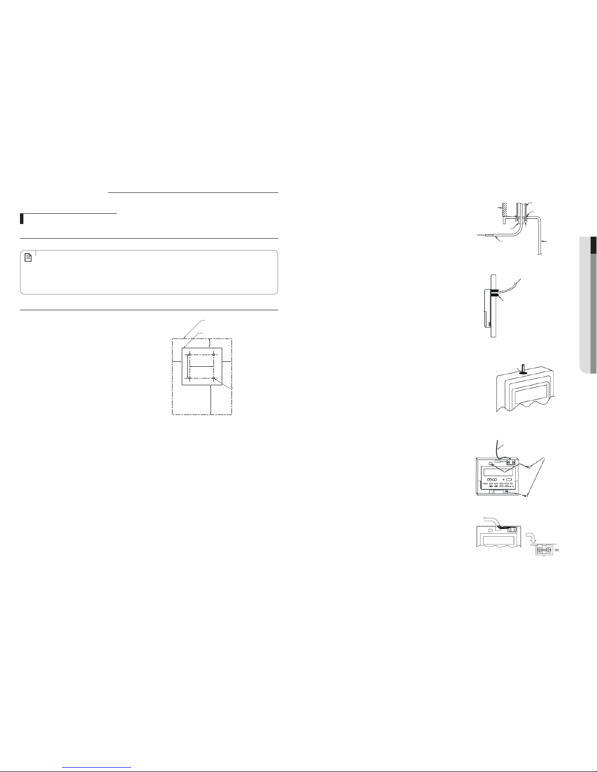
3. Seal the service entrance for the remote controller cable with putty
to prevent possible invasion of dew drops, water, cockroaches or
insects.
[A] For installation in the switch box
[B] For direct installation on the wall, select one of the followings:
• Prepare a hole through the wall to pass the remote controller
cable (in order to take out the remote controller cable from the
back), then seal the hole with putty.
• Take out the remote controller cable through the cut-out upper
case, then seal the cut-out notch with putty.
Wall
Remote controller
cable
Seal with putty
Conduit
Lock nut
Switch box
Bushing
[A]
Seal with putty
Remote controller cable
(To lead the remote controller cable from the back of
the controller)
Seal with putty
(To take out the remote controller cable through the
upper portion)
Remote controller cable
Wood screw
[B]
4. Connect the remote controller cable to the terminal block.
TB6 (No polarity)
To TB62 No.5 and 6 on the FTC unit
Installing the unit
Installing the remote controller
Connecting the wired remote controller cable to FTC
Connect the wired remote controller cable to 5 and 6 on the terminal block (TB62) on the FTC controller.
• Wiring wire No.×size(mm2) : 2×0.3(polar)
• The 5m wire is attached as an accessory. Max. 500 m
• Wiring size must comply with the applicable local and national codes.
• Circuit rating : DC12V
Circuit rating is NOT always against the ground.
NOTE
Installing the wired remote controller
1. Select an installing position for the remote controller.
Required clearances surrounding
the remote controller
Installation pitch
Remote controller profile
30
83.5
120
30
46
30
2. Procure the following parts locally :
• 2 piece switch box
• Thin copper conduit tube
• Lock nuts and bushings
8 9
ENGLISH
Power and communication with outdoor unit
Communication Wire
Power Wire
Connecting the power wire
1. Connect ‘Live’ and ‘Neutral’ power line with ‘pin #1’ and ‘pin #2’ in TB-A.
2. Connect ‘Protective Earth’ line with ‘Earth screw’ in case.
Recommended wire specification
Load Power Supply
Power Cable Max. Length Type GL
mm
2
, wires m A
Do NOT use Heater
(Water Pump, Valve,
Wired RMC)
1Ø, 220-240V, 50Hz
1.5 / 3 L < 10m 10~
2.5 / 3 10m < L 10~
Use Booster Heater
(3kw)
4.0 / 3 L < 10m 30
6.0 / 3 10m < L 30
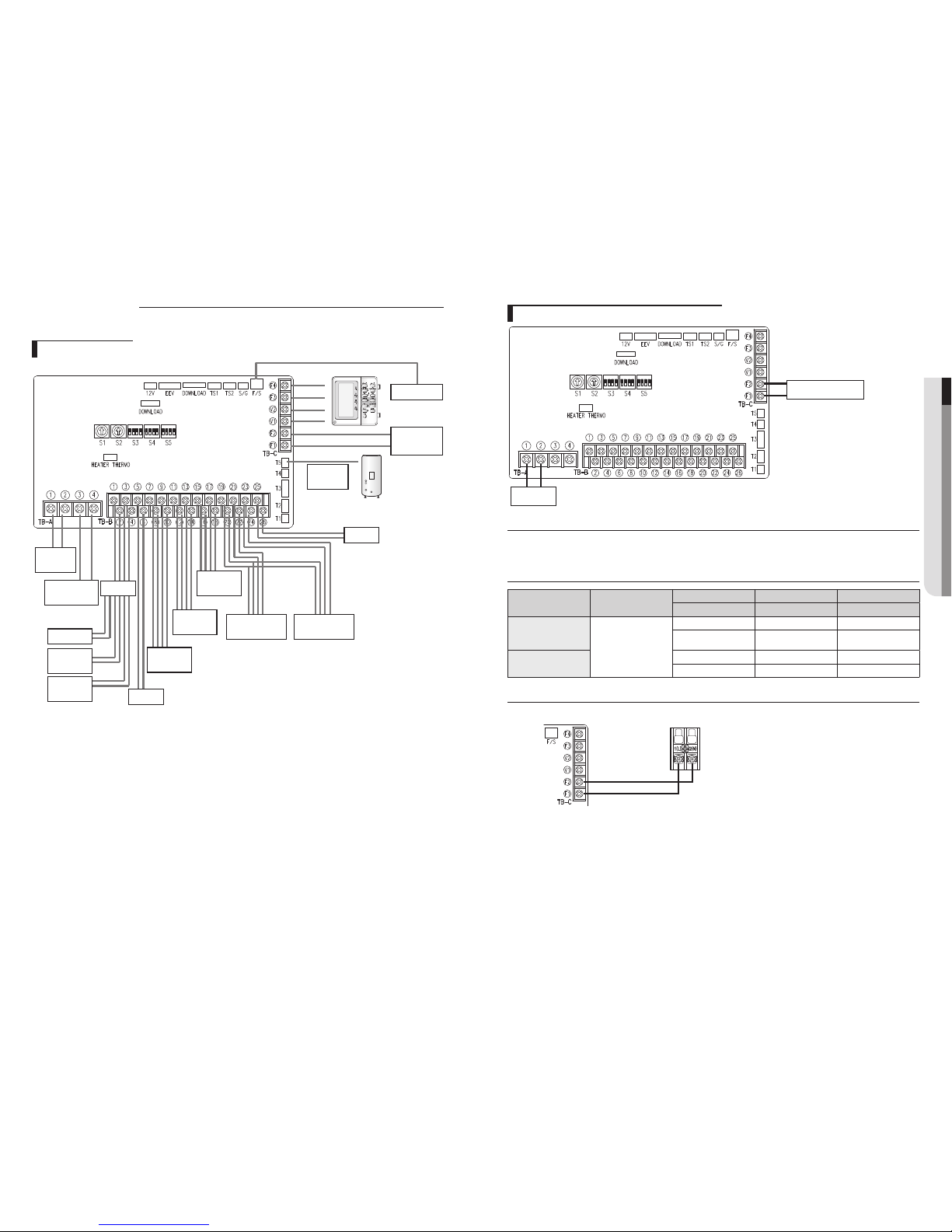
Connecting the communication wire
Connect ‘outdoor unit’s F1&F2’ with ‘control kit’s F1&F2 in TB-C’ by 2 core cable.
Outdoor Unit
(at Control Plate)
Control Kit
Wiring works
Overall schematics
Flow S/W
Outdoor Unit
Temp Sensor
Solar
Main Power
Relay
Pump
Booster Heater
Boiler
Back up
heater1
Back up
heater2
2way Valve
(DHW)
2way Valve
(Zone1)
2way Valve
(Zone2)
Wired Room
Thermostat1
Wired Room
Thermostat1
 Loading...