

Samsung MHFEEA Series, MHFUEA Series, MH070FXEA4B, MH060FXEA3B, MH050FXEA2B Installation Manual
ENGLISH
Free Joint Multi Air Conditioner
(Cooling and Heating)
INSTALLATION
MANUAL
MH
FEEA Series
MH
FUEA Series
ESPAÑOLFRANÇAISITALIANOPORTUGUÊSDEUTSCH
EΛΛHNIKA
DB98-29566A(2)
SE F I DP G

E-2
Safety Precautions
Keep this installation manual together with the user’s manual in a handy place so that you can find it whenever
you need to see it after reading this manual thoroughly.
Make sure to read the following safety precautions carefully before installation.
Make sure to observe the cautions specified in this manual.
Conduct a test run of the unit after installation and then explain all system functions to the owner.
The indications and meanings are as shown below.
WARNING
This indicates the possibility of serious injury or death.
Installation must be carried
out by a qualified installer.
Installers are required to read
the general information
carefully for safety.
Do not put the unit near
dangerous substances to
prevent fire, explosion or
injury and do not expose
the unit to direct sunlight.
Do not install the unit by
yourself (owners).
Incorrect installation of the
unit could cause injury due
to fire, electric shock and
water leakage or from the
unit falling. Consult a dealer
or a qualified installer.
Install the unit in a place
where it is strong enough
to hold the product weight.
When installed in place
where it is not strong
enough to withhold the
product weight, the unit
could fall and cause injury.
The units must be installed
according to distances
declared, in order to permit
accessibility from each side,
either to guarantee correct
operation of maintenance
or repairing products. The
unit’s parts must be reachable and removable completely under safety condition (for people or things)
Use the specified wires to
connect the indoor and
outdoor units securely and
attach the wires firmly to the
terminal block connecting
sections so that the pressure
is not applied to the sections.
Inappropriate connection and
fixing could cause fire.
Avoid the use of an
extension cord and do not
share the power outlet with
other appliances. Incomplete
connection, defective
insulation or exceeding the
permissible current may cause
electric shock or fire.
Make sure that the refrigerant
gas does not leak after
completing the installation.
If the refrigerant gas of
the indoor unit leaks and
comes into contact with the
fan heater, space heater or
stove, harmful substances
will be generated.
Perform the installation
securely referring to
the installation manual.
Incomplete installation
could cause personal injury
due to fire, electric shock
and water leakage or from
the unit falling.
Attach the electrical cover
to the indoor and outdoor
unit securely. If not, it could
result in fire or electric
shock due to dust or water.
Make sure to use the part
provided or specified parts
for the installation work.
The use of defective parts
could cause an injury or
leakage of water due to a
fire, an electric shock, the
unit falling, etc.
Make sure to turn off
the main power when
setting up the indoor unit
electrical circuit or power
cords.
There is a risk of electric
shock.
E-3
ENGLISH
CAUTION
This indicates the possibility of serious injury or damage to environments when
operated incorrectly
.
Check the unit for damage
that may have taken place
during transportation and do
not install or use damaged
equipment.
All of the manufacturing and
packaging material used for
your new appliance are
compatible with the
environment and can be
recycled.
Dispose of the packaging
material in accordance with
the local requirements.
This product is an air
conditioning system and
contains a coolant that must
be recovered and disposed
of in an appropriate way by
qualified personnel. At the
end of the life cycle, take it to
a proper recycling or disposal
center or return it to the
dealer so that it can be
disposed correctly.
Grounding the unit.
Do not connect the ground
to a gas pipe, water pipe,
lightning rod or telephone
grounding. Defective
grounding could cause
electric shock.
Do not install the unit in a
place where it is exposed to
inflammable gas leakage.
There is a risk of explosion.
Install a ground leakage
breaker depending on the
installation place (where it is
humid). If not, it may cause
electric shock.
Perform the drainage/piping
work securely according to
the installation manual.
If not, water could drop from
the unit and household
goods could get wet and
damaged.
Fasten a flare nut with a
torque wrench as specified
in this installation manual.
When fastened too tight,
a flare nut may break after
a long period of time and
cause refrigerant leakage.
To prevent injury when
accidentally touching the
indoor unit fan, install the
indoor unit on a place higher
than 2.5m.
The air conditioner must be
installed according to the
national electrical
regulations.
The maximum input power &
current is measured
according to the IEC standard
and the input power &
current is measured
according to the ISO and
EN14511standard.
WARNING
This indicates the possibility of serious injury or death.
The unit should be installed in
accordance with the National
Electrical regulations.
Ensure that the national safety
code requirements have been
followed for the main supply
circuit. Ensure that a properly
sized and connected ground
wire is in place.
Check if the voltage and the
frequency of the main power
supply are those required for
the unit to be installed and
check the connection.
Make sure that properly sized
disconnecting and safety
switches are installed.
Do not attempt to repair,
move, modify or reinstall
the unit on your own. Make
sure that these installations
are carried out by qualified
personnel to avoid electric
shock or fire.
Use the unit on a single outlet
circuit. Do not share the power
outlet with other appliances.
Obtain the consent by a
qualified installer before
connecting the unit to the
power supply system.

E-4
Contents
Preparation for installation . . . . . . . . . . . . . . . . . . . . . . . . . . . . . . . . . . . . . . . . . . . . . . . . . . . . . . . . . . . . 5
Deciding on where to install the Air Conditioner . . . . . . . . . . . . . . . . . . . . . . . . . . . . . . . . . . . . . 6
Air Conditioner and Accessories . . . . . . . . . . . . . . . . . . . . . . . . . . . . . . . . . . . . . . . . . . . . . . . . . . . . . . 10
Deciding on where to install the indoor unit . . . . . . . . . . . . . . . . . . . . . . . . . . . . . . . . . . . . . . . . . . 11
Indoor unit installation . . . . . . . . . . . . . . . . . . . . . . . . . . . . . . . . . . . . . . . . . . . . . . . . . . . . . . . . . . . . . . . . 14
Purging the unit . . . . . . . . . . . . . . . . . . . . . . . . . . . . . . . . . . . . . . . . . . . . . . . . . . . . . . . . . . . . . . . . . . . . . . 15
Connecting the refrigerant pipe . . . . . . . . . . . . . . . . . . . . . . . . . . . . . . . . . . . . . . . . . . . . . . . . . . . . . . 15
Cutting/Flaring the pipes . . . . . . . . . . . . . . . . . . . . . . . . . . . . . . . . . . . . . . . . . . . . . . . . . . . . . . . . . . . . . 16
Performing leak test & insulation . . . . . . . . . . . . . . . . . . . . . . . . . . . . . . . . . . . . . . . . . . . . . . . . . . . . . 17
Drain hose installation . . . . . . . . . . . . . . . . . . . . . . . . . . . . . . . . . . . . . . . . . . . . . . . . . . . . . . . . . . . . . . . . 18
Connecting the connection cord . . . . . . . . . . . . . . . . . . . . . . . . . . . . . . . . . . . . . . . . . . . . . . . . . . . . . 20
Increasing Fan Speed . . . . . . . . . . . . . . . . . . . . . . . . . . . . . . . . . . . . . . . . . . . . . . . . . . . . . . . . . . . . . . . . . 22
Assigning Address to Indoor Unit . . . . . . . . . . . . . . . . . . . . . . . . . . . . . . . . . . . . . . . . . . . . . . . . . . . . . 23
Additional Functions . . . . . . . . . . . . . . . . . . . . . . . . . . . . . . . . . . . . . . . . . . . . . . . . . . . . . . . . . . . . . . . . . . 24
Filter Replacement . . . . . . . . . . . . . . . . . . . . . . . . . . . . . . . . . . . . . . . . . . . . . . . . . . . . . . . . . . . . . . . . . . . . 25
Drain pump Installation (Optional) . . . . . . . . . . . . . . . . . . . . . . . . . . . . . . . . . . . . . . . . . . . . . . . . . . . . 27
Placing the Indoor Unit in Position . . . . . . . . . . . . . . . . . . . . . . . . . . . . . . . . . . . . . . . . . . . . . . . . . . . . 29
Troubleshooting . . . . . . . . . . . . . . . . . . . . . . . . . . . . . . . . . . . . . . . . . . . . . . . . . . . . . . . . . . . . . . . . . . . . . . 30
E-5
ENGLISH
COMPLETING THE INSTALLATION
Preparation for installation
When deciding on the location of the air conditioner with the owner,
the following restrictions must be taken into account.
Do NOT install the air conditioner in a location where it will come into
contact with the following elements:
Combustible gases
Saline air
Machine oil
Sulphide gas
Special environmental conditions
If you must install the unit in such conditions, first consult your dealer.
General
Avoid installing the air conditioner:
In areas where it is exposed to direct sunlight. Close to heat sources.
In damp areas or locations where it could come into contact with water
(for example rooms used for laundry)
In areas where curtains and furniture could affect the supply and discharge of air.
Without leaving the required minimum space around the unit (as shown in the
drawing).
In scarcely ventilated areas.
On surfaces that are unable to support the weight of the unit without deforming,
breaking or causing vibrations during the use of the air conditioner.
In a position that does not enable the condensate drainage pipe to be correctly
installed (at the end of the installation. It is always essential to check the efficiency
of the drainage system.)
You have just purchased a Free Joint Multi air conditioner and it has been installed byyour installa-
tion specialist.
This device must be installed according to the national electrical rules.
Max input power & current is measured according to IEC standard and input power ¤t is
measured according to ISO standard.
CAUTION

E-6
COMPLETING THE INSTALLATION
Deciding on where to install the Air Conditioner
Indoor unit
There must be no obstacles near the air inlet and outlet.
Install the indoor unit on a ceiling that can support its weight.
Maintain sufficient clearance around the indoor unit.
Make sure that the water dripping from the drain hose runs away correctly and safely.
The indoor unit must be installed in this way, that they are out of public access. (Not touchable by the users)
After connecting a chamber, insulate the connection part between the indoor unit and the chamber with t10 or
thicker insulation. Otherwise, there can be air leak or dew from the connection part.
You must have 20mm or more space between the ceiling and the bottom of indoor unit. Otherwise, the noise from the vibration of
indoor unit may bother the user.When the ceiling is under construction, the hole for check-up must be made to take service, clean
and repair the unit.
It is possible to install the unit at an height of between 2.2~2.5m from the ground, if the unit has a duct with a well defined lenght
(300mm or more), to avoid fan motor blower contact.
Space requirements for installation & service
Construction Standard for Inspection Hole.
1) In case, the ceiling is textile, Inspection hole dose not need.
2) In case, the ceiling is plaster board, Inspection hole depends on Inside height of the ceiling.
a. Height is more than 1m : Only “B” [Inspection for PBA] is applied.
b. Height is less than 1m : Both “A” & ”B” are applied.
c. “A” & ”B” are inspection holes.
Unit Width(W)
“A”=W+100mm “B”=500mm
Unit Depth(D)+50mm
20mm or more
20mm or more
E-7
ENGLISH
COMPLETING THE INSTALLATION
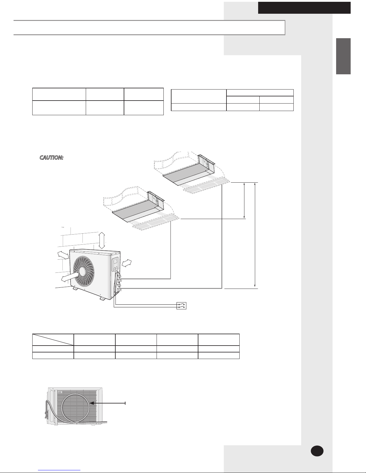
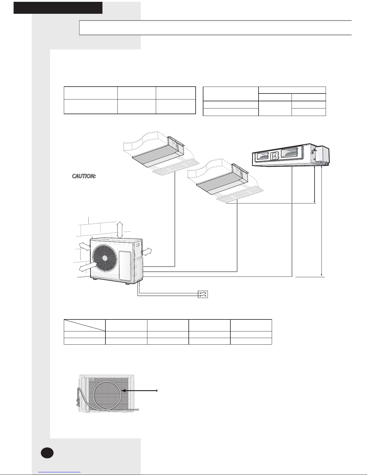
MH050FXEA2B
Indoor unit Outdoor unit
Power supply
Ø, V, Hz
026/035
MH050FXEA2B 1,220-240, 50
Unit
Outside diameter
Liquid Gas
026/035
1/4" 3/8"
MH050FXEA2B outdoor unit cannot be connected to the following indoor unit combination.
-MH052FMEA/MH052FUEA/MH052FEEA
Piping outside diameter
(h) (H)
A
B
600 mm
minimum
1 Room max
length
2 Room total max
length
Max height between
indoor unit & outdoor unit
Max height between
indoor units
Dimension 20m 30 m 15m 7.5 m
Composition A,B A+B (H) (h)
Piping length and the height
Main power switch
300 mm
minimum
300 mm
minimum
600 mm
minimum
CAUTION:
3 m as minimum pipe length: It will reduce
noise and vibration.
This value must be increased at 7.5 meters
in case it is connected just one indoor unit.
System can work with one indoor unit connected, but it is recommended that the TOTAL number
of indoor unit suggested by manufacturer are connected to obtain the maximum performance.
The appearance of the unit may be different from the diagram depending on the model.
Make at least one round:
It will reduce noise and vibration
E-8
COMPLETING THE INSTALLATION
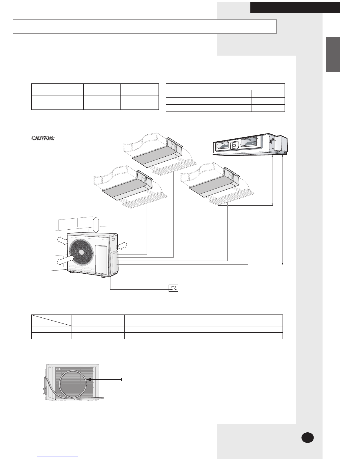
MH060FXEA3B
Indoor unit Outdoor unit
Power supply
Ø, V, Hz
026/035/052
MH060FXEA3B 1,220-240, 50
Unit
Outside diameter
Liquid Gas
026/035
1/4"
3/8"
052
1/2"
Piping outside diameter
(h)
(H)
A
B
1 Room max
length
3 Room total max
length
Max height between
indoor unit & outdoor unit
Max height between
indoor units
Dimension 20m 45 m 15m 7.5 m
Composition A,B,C A+B+C (H) (h)
Piping length and the height
Main power switch
C
600 mm
minimum
300 mm
minimum
600 mm
minimum
300 mm
minimum
CAUTION:
3 m as minimum pipe length: It will reduce
noise and vibration.
This value must be increased at 7.5 meters in
case it is connected just one indoor unit.
System can work with one indoor unit connected, but it is recommended that the TOTAL number
of indoor unit suggested by manufacturer are connected to obtain the maximum performance.
The appearance of the unit may be different from the diagram depending on the model.
Make at least one round:
It will reduce noise and vibration
Deciding on where to install the Air Conditioner (Continue)
E-9
ENGLISH
COMPLETING THE INSTALLATION
MH070FXEA4B / MH080FXEA4B
Indoor unit Outdoor unit
Power supply
Ø, V, Hz
026/035/052
MH070FXEA4B
MH080FXEA4B
1,220-240, 50
Unit
Outside diameter
Liquid Gas
026/035
1/4" 3/8"
052
1/4" 1/2"
Piping outside diameter
(h) (H)
A
B
1 Room max
length
4 Room total max
length
Max height between
indoor unit & outdoor unit
Max height between
indoor units
Dimension 25m 70 m 15m 7.5 m
Composition A,B,C,D A+B+C+D (H) (h)
Piping length and the height
C D
Main power switch
600 mm
minimum
300 mm
minimum
300 mm
minimum
600 mm
minimum
CAUTION:
3 m as minimum pipe length: It will
reduce noise and vibration.
This value must be increased at 7.5
meters in case it is connected just one
indoor unit.
System can work with one indoor unit connected, but it is recommended that the TOTAL number
of indoor unit suggested by manufacturer are connected to obtain the maximum performance.
The appearance of the unit may be different from the diagram depending on the model.
Make at least one round:
It will reduce noise and vibration
E-10
COMPLETING THE INSTALLATION
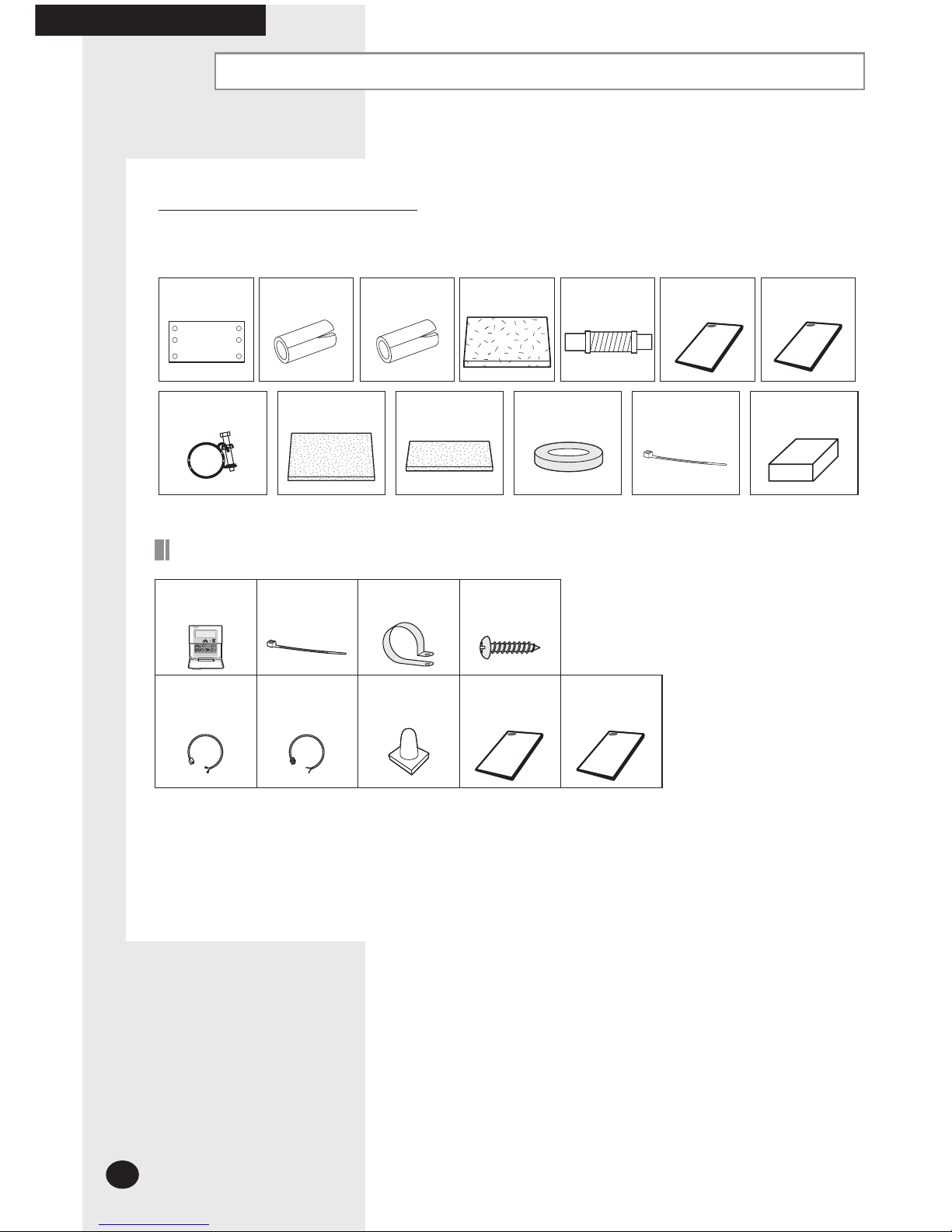
Air Conditioner and Accessories
Accessories in the Indoor Unit Case
The following accessories are supplied with the indoor unit.
Pattern Sheet Insulation A Insulation B Insulation C Flexible hose
Drain pipe holder Insulation
D Insulation
cover band E
Putty Cable-Tie Wired remote
controller box
Wired remote control accessories
Wired remote
control
Cable-tie Cable clamp M4x16
tapped screw
Indoor unit power
drawing cable
Communication
cable of the wired
remote control
Wire joint User’s
manual
Installation
manual
Installation
manual
User’s
manual
 Loading...