

Samsung LE27S73BD, LE32S66BD, LE40S73BD, LE32S74BD, LE32S73BD Service Manual
...
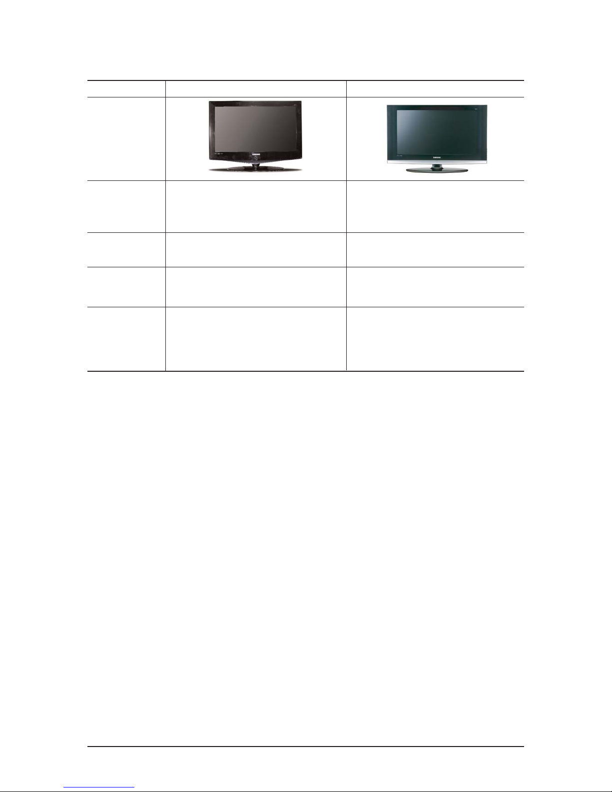
TFT-LCD TV
Chassis GSD27SEN
GSD32HEU
GSD37SEN
GSD40SEN
Model LE27S73BD
LE32S73BD
LE32S66BD
LE37S73BD
LE40S73BD
LE32S74BD
Manual
SERVICE
TFT-LCD TV Fashion Feature
- Luxurious Slim Design
- Supreme Picture Quality
- Supreme Sound Quality
- Supreme Convenience Quality
- Convenience for Users
- DVB-T, iDTV
- MHP (Only for Italy, Spain)

ii
Copyright
ⓒ 2007 by Samsung Electronics Co., Ltd.
All rights reserved.
This manual may not, in whole or in part, be copied,
photocopied, reproduced, translated, or converted to any
electronic or machine readable form without prior
written permission of Samsung Electronics Co., Ltd.
LE27S73BD/LE32S66BD/LE37S73BD/
LE40S74BD Service Manual
First edition April 2007.
Printed in Korea.
Trademarks
Samsung is the registered trademark of Samsung
Electronics Co., Ltd.
LE27S73BD/LE32S66BD/LE37S73BD/
LE40S74BD and Macmaster Cable Adapter are
trademarks of Samsung Electronics Co., Ltd.
Macintosh and Power Macintosh are trademarks of
Apple Computer, Inc.
All other trademarks are the property of their respective
owners.

Contents
11. Precautions
………………………………………………………………………………………………………………………………………
11-1
1-1 Safety Precautions ……………………………………………………………………………………………………………………… 1-1
1-2 Servicing Precautions …………………………………………………………………………………………………………………… 1-2
1-3 Static Electricity Precautions …………………………………………………………………………………………………………… 1-3
1-4 Installation Precautions…………………………………………………………………………………………………………………… 1-4
2
2. Product specifications
…………………………………………………………………………………………………………………………
22-1
2-1 Fashion Feature…………………………………………………………………………………………………………………………… 2-1
2-2 Technical and Environmental Specifications…………………………………………………………………………………………… 2-2
2-3 LE27S73BD Specifications ……………………………………………………………………………………………………………… 2-4
2-4 LE32S73BD Specifications ……………………………………………………………………………………………………………… 2-5
2-5 LE37S73BD Specifications ……………………………………………………………………………………………………………… 2-6
2-6 LE40S73BD Specifications ……………………………………………………………………………………………………………… 2-7
2-7 DTV Specification ………………………………………………………………………………………………………………………… 2-8
2-8 Spec Comparison ………………………………………………………………………………………………………………………… 2-9
2-9 Option Specification …………………………………………………………………………………………………………………… 2-10
3
3. Alignments and Adjustments
…………………………………………………………………………………………………………………
33-1
3-1 Service Instruction ……………………………………………………………………………………………………………………… 3-1
3-2 How to Access Service Mode …………………………………………………………………………………………………………… 3-2
3-3 Factory Data ……………………………………………………………………………………………………………………………… 3-3
3-4 Service Adjustment ……………………………………………………………………………………………………………………… 3-6
3-5 Software Upgrade ………………………………………………………………………………………………………………………… 3-8
3-6 DTV Program Download & Generals …………………………………………………………………………………………………… 3-9
4
4. Troubleshooting
………………………………………………………………………………………………………………………………
44-1
4-1 First Checklist for Troubleshooting ………………………………………………………………………………………………………4-1
4-2 Checkpoints by Error Mode ……………………………………………………………………………………………………………… 4-2
5
5. Exploded View and Parts List
…………………………………………………………………………………………………………………
55-1
5-1 LE27S73BD Exploded View …………………………………………………………………………………………………………… 5-1
5-2 LE27S73BD Parts list …………………………………………………………………………………………………………………… 5-2
5-3 LE32S66BD Exploded View …………………………………………………………………………………………………………… 5-3
5-4 LE32S66BD Parts list …………………………………………………………………………………………………………………… 5-4
5-5 LE37S73BD Exploded View …………………………………………………………………………………………………………… 5-5
5-6 LE37S73BD Parts list …………………………………………………………………………………………………………………… 5-6
5-7 LE40S73BD / LE40S74BD Exploded View …………………………………………………………………………………………… 5-7
5-8 LE40S73BD / LE40S74BD Parts list …………………………………………………………………………………………………… 5-8
6
6. Electrical Parts List
……………………………………………………………………………………………………………………………
66-1
6-1 LE27S73BD Parts List …………………………………………………………………………………………………………………… 6-1
6-2 LE32S66BD Parts List ………………………………………………………………………………………………………………… 6-25
6-3 LE37S73BD Parts List ………………………………………………………………………………………………………………… 6-47
6-4 LE40S73BD / LE40S74BD Parts List ………………………………………………………………………………………………… 6-68

Contents
77. Block Diagram
…………………………………………………………………………………………………………………………………
77-1
7-1 Main Block Diagram ……………………………………………………………………………………………………………………… 7-1
7-2 DTV Block Diagram ……………………………………………………………………………………………………………………… 7-2
7-3 DTV Block Diagram(Only for Italy/Spain) ……………………………………………………………………………………………… 7-5
7-4 DTV Power Block Diagram ……………………………………………………………………………………………………………… 7-6
8
8. Wiring Diagram
…………………………………………………………………………………………………………………………………
88-1
8-1 LE27S73BD/LE32S73BD/LE37S73BD/LE40S73BD Wiring Diagram ……………………………………………………………… 8-1
8-2 Main Board Layout ……………………………………………………………………………………………………………………… 8-2
8-3 PIN characteristic ………………………………………………………………………………………………………………………… 8-5
8-4 Power Board Layout ……………………………………………………………………………………………………………………… 8-6
9
9. Schematic Diagrams
……………………………………………………………………………………………………………………………
99-1
10. OOperating Instructions and Installation
………………………………………………………………………………………………………
110-1
10-1 Front …………………………………………………………………………………………………………………………………… 10-1
10-2 Connection Panel ……………………………………………………………………………………………………………………… 10-2
10-3 Remote Control ………………………………………………………………………………………………………………………… 10-5
10-4 Installing the Stand …………………………………………………………………………………………………………………… 10-6
10-5 Installing the Wall Mount Kit ………………………………………………………………………………………………………… 10-6
1
11. Disassembly and Reassembly
………………………………………………………………………………………………………………
111-1
11-1 Disassembly …………………………………………………………………………………………………………………………… 11-1
11-2 Reassembly …………………………………………………………………………………………………………………………… 11-5
1
12. PCB Diagram
…………………………………………………………………………………………………………………………………
112-1
12-1 27" Main PCB Diagram ……………………………………………………………………………………………………………… 12-1
12-2 32", 37", 40" Main PCB Diagram …………………………………………………………………………………………………… 12-2
12-3 DTV MODULE PCB Diagram (Only for Italy/Spain) ……………………………………………………………………………… 12-3
12-4 DTV MODULE PCB Diagram ………………………………………………………………………………………………………… 12-4
113. Circuit Descriptions
……………………………………………………………………………………………………………………………
113-1
13-1 Main Signal Description ……………………………………………………………………………………………………………… 13-1
13-2 DTV Signal Description ……………………………………………………………………………………………………………… 13-2
13-3 DTV Signal Description (Only for Italy/Spain)
……………………………………………………………………………………… 13-3
13-4 RF/DTV Tuner (DNOS303ZH261B(S)) SPEC.. …………………………………………………………………………………… 13-4
13-5 DTV MAIN ChipSet …………………………………………………………………………………………………………………… 13-8
13-6 DTV MAIN Chipset (Only for Italy/Spain) ………………………………………………………………………………………… 13-11
114. Reference Infomation
…………………………………………………………………………………………………………………………
114-1
14-1 Technical Terms ……………………………………………………………………………………………………………………… 14-1
14-2 Pin Assignments ……………………………………………………………………………………………………………………… 14-4
14-3 Timing Chart …………………………………………………………………………………………………………………………… 14-7
14-4 Panel Description …………………………………………………………………………………………………………………… 14-11
Samsung Electronics Co.,Ltd.
416, Maetan-3Dong, Yeongtong-Gu, Suwon City,
Gyeonggi-Do, Korea, 443-742
Printed in Korea
P/N : BN82-00139V-00
URL : http://itself.sec.samsung.co.kr/
- This Service Manual is a property of
Samsung Electronics Co., Ltd.
Any unauthorized use of Manual can be
punished under applicable International
and/or domestic law.
1 Precautions
1-1
1-1-1 Warnings
1. For continued safety, do not attempt to modify the
circuit board.
2. Disconnect the AC power and DC Power Jack before
servicing.
1-1-2 Servicing the LCD Monitor
1. When servicing the LCD Monitor Disconnect the AC
line cord from the AC outlet.
2. It is essential that service technicians have an accurate
voltage meter available at all times. Check the
calibration of this meter periodically.
1-1-3 Fire and Shock Hazard
Before returning the monitor to the user, perform the
following safety checks:
1. Inspect each lead dress to make certain that the leads
are not pinched or that hardware is not lodged between
the chassis and other metal parts in the monitor.
2. Inspect all protective devices such as nonmetallic
control knobs, insulating materials, cabinet backs,
adjustment and compartment covers or shields,
isolation resistor-capacitor networks, mechanical
insulators, etc.
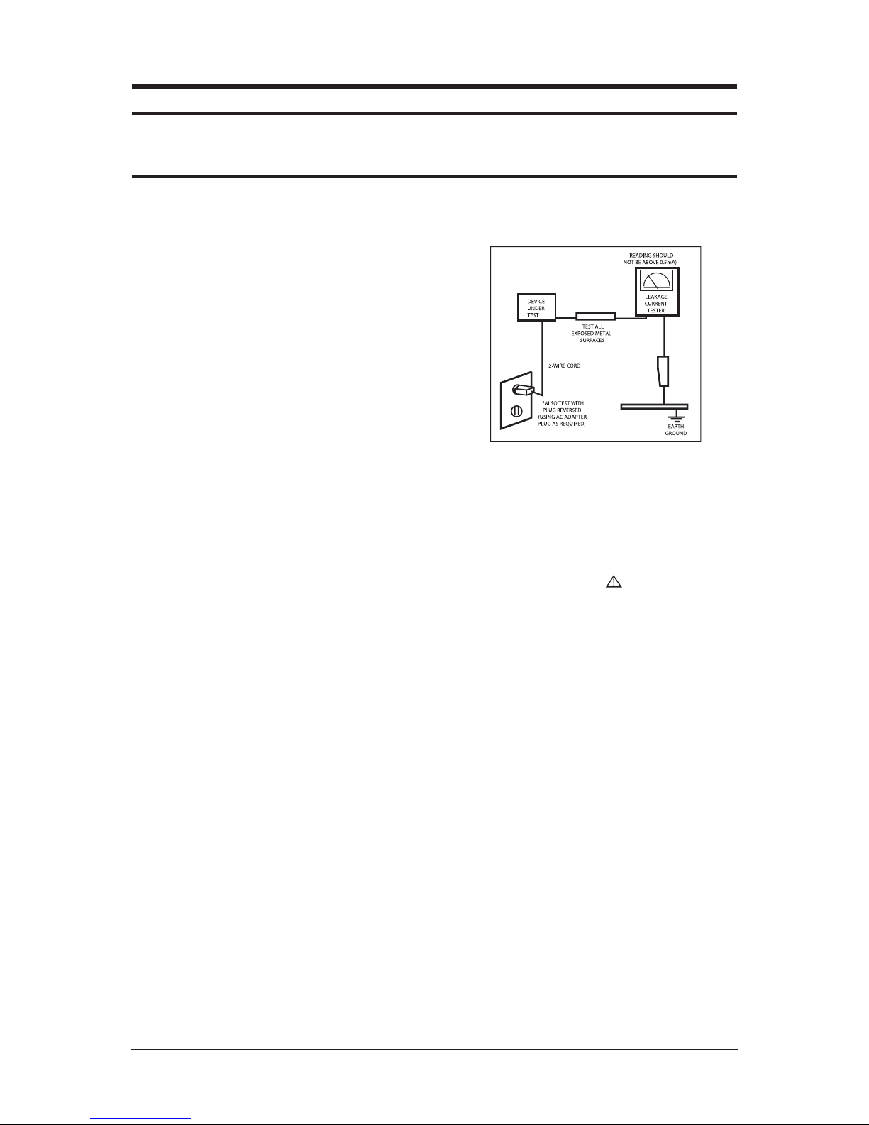
3. Leakage Current Hot Check (Figure 1-1):
WARNING: Do not use an isolation
transformer during
this test.
Use a leakage current tester or a metering system that
complies with American National Standards Institute
(ANSI C101.1, Leakage Current for Appliances), and
Underwriters Laboratories (UL Publication UL1410,
59.7).
Figure 1-1. Leakage Current Test Circuit
1-1-4 Product Safety Notices
Some electrical and mechanical parts have special
safety-related characteristics which are often not evident
from visual inspection. The protection they give may not
be obtained by replacing them with components rated for
higher voltage, wattage, etc. Parts that have special safety
characteristics are identified by on schematics and parts
lists. A substitute replacement that does not have the same
safety characteristics as the recommended replacement part
might create shock, fire and/or other hazards. Product
safety is under review continuously and new instructions
are issued whenever appropriate.
1 Precautions
Follow these safety, servicing and ESD precautions to prevent damage and to protect against potential hazards such as electrical shock.
1-1 Safety Precautions

1 Precautions
1-2
1-2-1 General Ser vicing
Precautions
1. Always unplug the units AC power cord from the AC
power source and disconnect the DC Power Jack
before attempting to:
(a) remove or reinstall any component or assembly, (b)
disconnect PCB plugs or connectors, (c) connect a test
component in parallel with an electrolytic capacitor.
2. Some components are raised above the printed circuit
board for safety. An insulation tube or tape is
sometimes used. The internal wiring is sometimes
clamped to prevent contact with thermally hot
components. Reinstall all such elements to their
original position.
3. After servicing, always check that the screws,
components and wiring have been correctly
reinstalled. Make sure that the area around the
serviced part has not been damaged.
1. Immediately before handling any semiconductor
components or assemblies, drain the electrostatic
charge from your body by touching a known earth
ground. Alternatively, wear a discharging wrist-strap
device. To avoid a shock hazard, be sure to remove the
wrist strap before applying power to the monitor.
2. After removing an ESD-equipped assembly, place it
on a conductive surface such as aluminum foil to
prevent accumulation of an electrostatic charge.
3. Do not use freon-propelled chemicals. These can
generate electrical charges sufficient to damage ESDs.
4. Use only a grounded-tip soldering iron to solder or
desolder ESDs.
5. Use only an anti-static solder removal device. Some
solder removal devices not classified as anti-static
can generate electrical charges sufficient to damage
ESDs.
4. Check the insulation between the blades of the AC
plug and accessible conductive parts (examples: metal
panels, input terminals and earphone jacks).
5. Insulation Checking Procedure: Disconnect the power
cord from the AC source and turn the power switch
ON. Connect an insulation resistance meter (500 V) to
the blades of the AC plug.
The insulation resistance between each blade of the
AC plug and accessible conductive parts (see above)
should be greater than 1 megohm.
6. Always connect a test instruments ground lead to the
instrument chassis ground before connecting the
positive lead; always remove the instruments ground
lead last.
6. Do not remove a replacement ESD from its protective
package until you are ready to install it. Most
replacement ESDs are packaged with leads that are
electrically shorted together by conductive foam,
aluminum foil or other conductive materials.
7. Immediately before removing the protective material
from the leads of a replacement ESD, touch the
protective material to the chassis or circuit assembly
into which the device will be installed.
Caution: Be sure no power is applied to
the chassis or circuit and
observe all other safety
precautions.
8. Minimize body motions when handling unpackaged
replacement ESDs. Motions such as brushing clothes
together, or lifting your foot from a carpeted floor can
generate enough static electricity to damage an ESD.
1-3 Static Electricity Precautions
Some semiconductor (solid state) devices can be easily damaged by static electricity. Such components are commonly called
Electrostatically Sensitive Devices (ESD). Examples of typical ESD are integrated circuits and some field-effect transistors.
The following techniques will reduce the incidence of component damage caused by static electricity.
1-2 Ser vicing Precautions
WARNING: An electrolytic capacitor installed with the wrong polarity might explode.
Caution: Before servicing units covered by this service manual, read and follow the Safety
Precautions section of this manual.
Note: If unforeseen circumstances create conflict between the following servicing precautions and any of the safety
precautions, always follow the safety precautions.

1. For safety reasons, more than two people are
required for carrying the product.
2. Keep the power cord away from any heat emitting
devices, as a melted covering may cause fire or
electric shock.
3. Do not place the product in areas with poor
ventilation such as a bookshelf or closet. The
increased internal temperature may cause fire.
4. Bend the external antenna cable when connecting
it to the product. This is a measure to protect it
from being exposed to moisture. Otherwise, it
may cause a fire or electric shock.
5. Make sure to turn the power off and unplug the
power cord from the outlet before repositioning
the product. Also check the antenna cable or the
external connectors if they are fully unplugged.
Damage to the cord may cause fire or electric
shock.
6. Keep the antenna far away from any high-voltage
cables and install it firmly. Contact with the highvoltage cable or the antenna falling over may
cause fire or electric shock.
7. When installing the product, leave enough space
(10cm) between the product and the wall for
ventilation purposes.
A rise in temperature within the product may
cause fire.
1 Precautions
1-3
1-4 Installation Precautions

Memo
1 Precautions
1-4

2 Product Specifications
2-1
2 Product specifications
2-1 Fashion Feature
Supreme Digital Interface & Networking
-With a built-in HD digital tuner, it supports HD broadcasting with no particular set-top box and provides
simple access with a single remote control.
Excellent Picture Quality
-DNIe technology provides life-like clear images.
Dynamic Contrast
-Automatically detects the input visual signal and adjusts to create optimum contrast.
SRS TruSurround XT
-SRS TruSurround XT provides a virtual Dolby surround system.
Convenience
-The TV utilizes the HDMI system to implement perfect digital sound and picture quality.
-Supports DVB-CI (Common Interface)
-Supports Modem (Only for Italy/Spain)
-Supports SMART CARD (NON CAS / Only for Italy / Spain)
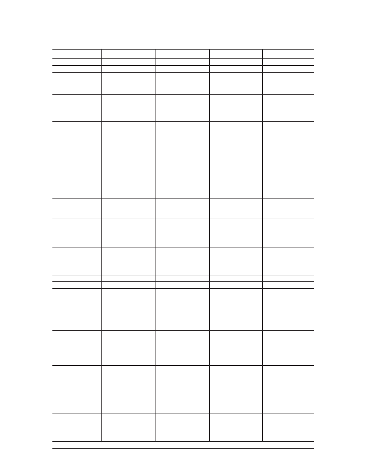
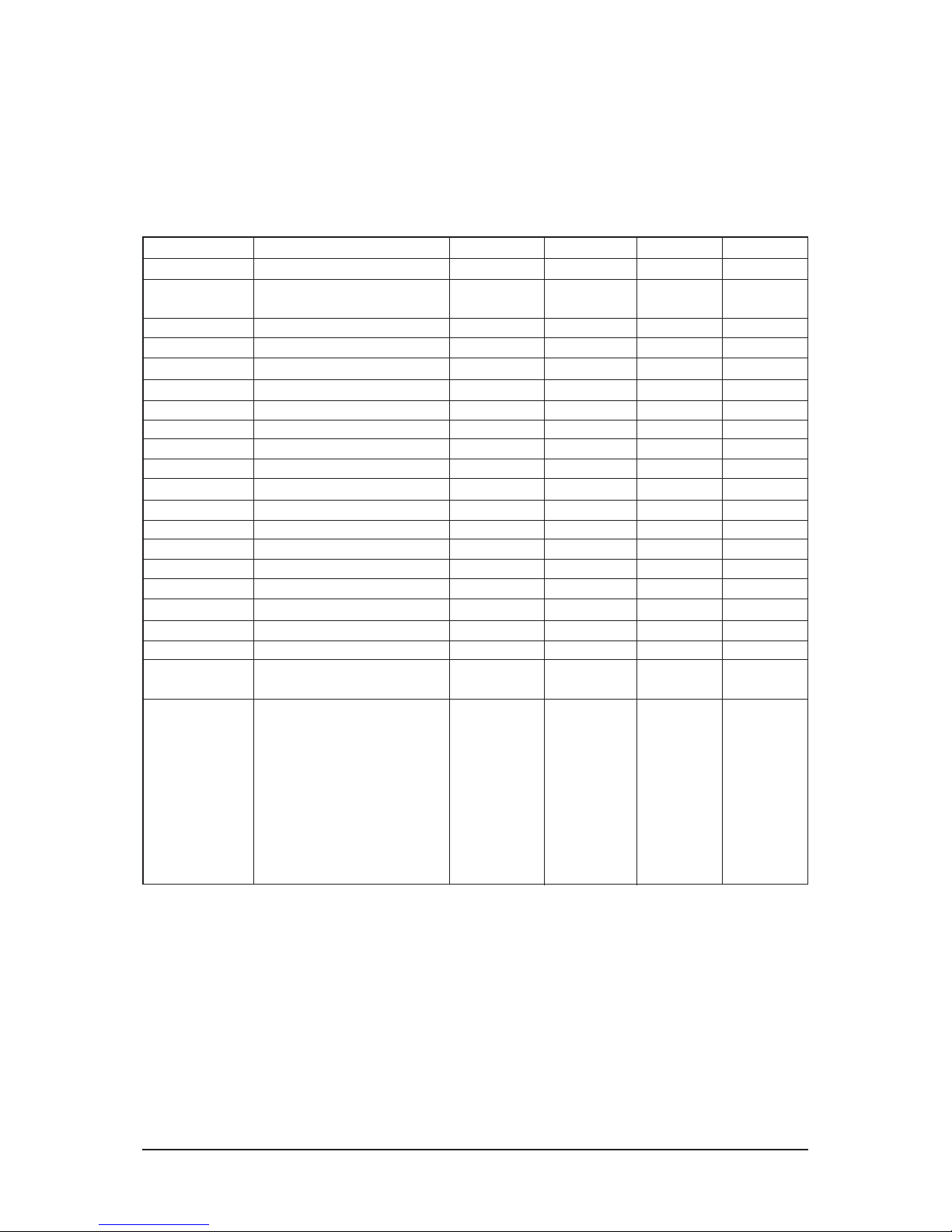
2-2 Technical and Environmental Specifications
2 Product Specifications
2-2
Model Name LE27S73BD LE32S73BD LE37S73BD LE40S73BD
Screen Size (Diagonal)
PC Resolution
Input Signal
Sync.
Video Signal
TV
Colour System
Sound System
DTV Signal Reception
UHF Cgannel
Demodulation
DTV Video/ Audio Decoding
Video Decoding
Bit rate
Resolution
Audio Decoding
Sound Mode
Video
Colour System
Video System
SCART 1
Video Input/Output
RGB Input
Audio Input/Output
SCART 2
Video Input/Output
Audio Input/Output
Power Supply
Power Consumption
Stand-by
Dimension (W x D x H)
Body
With stand
Weight (With stand)
Environmental Considerations
Operating Temperature
Operating Humidity
Storage Temperature
Storage Humidity
Audio Characteristics
Audio Input
Audio Input (PC)
Headphone Output
Frequency
Response
Sound
Output
3D Surround
Stereo
27 inch
1360 x 768 @ 60 Hz
H/V Separate, TTL, P. or N.
0.7 Vp-p @ 75 ohm
PAL, SECAM-B/G, D/K,
I, I/I, L/L¡¯, NTPB (AV3.58, 4.43)
BG, DK, I, L
Channel 21~68 (474~850 MHz)
Bandwidth 8 MHz
DVB-T
MPEG2 DVB Compliant
(Main Profile @ Main Level)
UP to 1 5 Mb/s
720 x 576 pixels
MPEG-2 Layer I & II
Mono/Stereo
PAL/NTSC/SECAM
CVBS, S-VHS, RGB
1.0 Vp-p @ 75 ohm
0.7 Vp-p @ 75 ohm
500 mVrms
1.0 Vp-p @ 75 ohm
500 mVrms
AC220-240V 50 Hz
140 W
< 1 W
769.0 X 79.0 X 471.0 mm
(30.3 X 3.1 X 1 8.5 inches)
769.0 X 226.0 X 526.0 mm
(30.3 X 8.9 X 20.7 inches)
10.4 kg (22.9 Ibs)
10 ¡ÆC to 40 ¡ÆC (50 ¡ÆF to 1 04 ¡ÆF)
10 % to 80 %, non-condensing
-20 ¡ÆC to 45 ¡ÆC (-4 ¡ÆF to 11 3 ¡ÆF)
5 % to 95 %, non-condensing
RCA Jack(L, R), 0.5 Vrms(-9 dB)
3.5 ¨ª Stereo Jack, 0.5 Vrms (-9 dB)
Max. 1 0 mW Output
(3.5 ¨ª Stereo Jack, 32 ¥Ø)
RF: 80 Hz ~ 1 5 kHz (at -3 dB)
A/V: 80 Hz ~ 20 kHz (at -3 dB)
5 W X 2
SRS TrusurroundXT
Nicam/A2
32 inch
1360 x 768 @ 60 Hz
H/V Separate, TTL, P. or N.
0.7 Vp-p @ 75 ohm
PAL, SECAM-B/G, D/K,
I, I/I, L/L¡¯, NTPB (AV3.58, 4.43)
BG, DK, I, L
Channel 21~68 (474~850 MHz)
Bandwidth 8 MHz
DVB-T
MPEG2 DVB Compliant
(Main Profile @ Main Level)
UP to 1 5 Mb/s
720 x 576 pixels
MPEG-2 Layer I & II
Mono/Stereo
PAL/NTSC/SECAM
CVBS, S-VHS, RGB
1.0 Vp-p @ 75 ohm
0.7 Vp-p @ 75 ohm
500 mVrms
1.0 Vp-p @ 75 ohm
500 mVrms
AC220-240V 50 Hz
152 W
< 1 W
892.5 X 82.0 X 544.0 mm
(35.1 X 3.2 X 21.4 inches)
892.5 X 249.0 X 615.0 mm
(35.1 X 9.8 X 24.2 inches)
13.9 kg (30.6 Ibs)
10 ¡ÆC to 40 ¡ÆC (50 ¡ÆF to 1 04 ¡ÆF)
10 % to 80 %, non-condensing
-20 ¡ÆC to 45 ¡ÆC (-4 ¡ÆF to 11 3 ¡ÆF)
5 % to 95 %, non-condensing
RCA Jack(L, R), 0.5 Vrms(-9 dB)
3.5 ¨ª Stereo Jack, 0.5 Vrms (-9 dB)
Max. 1 0 mW Output
(3.5 ¨ª Stereo Jack, 32 ¥Ø)
RF: 80 Hz ~ 1 5 kHz (at -3 dB)
A/V: 80 Hz ~ 20 kHz (at -3 dB)
10 W X 2
SRS TrusurroundXT
Nicam/A2
37 inch
1360 x 768 @ 60 Hz
H/V Separate, TTL, P. or N.
0.7 Vp-p @ 75 ohm
PAL, SECAM-B/G, D/K,
I, I/I, L/L¡¯, NTPB (AV3.58, 4.43)
BG, DK, I, L
Channel 21~68 (474~850 MHz)
Bandwidth 8 MHz
DVB-T
MPEG2 DVB Compliant
(Main Profile @ Main Level)
UP to 1 5 Mb/s
720 x 576 pixels
MPEG-2 Layer I & II
Mono/Stereo
PAL/NTSC/SECAM
CVBS, S-VHS, RGB
1.0 Vp-p @ 75 ohm
0.7 Vp-p @ 75 ohm
500 mVrms
1.0 Vp-p @ 75 ohm
500 mVrms
AC220-240V 50 Hz
170 W
<1W
1026.5 ¡¿ 94.1 ¡¿ 626.1 mm
(40.4 X 3.7 X 24.6 inches)
1026.5 ¡¿ 330.0 ¡¿ 698.8 mm
(40.4 X 1 3.0 X 27.5 inches)
22.5 kg (49.6 Ibs)
10 ¡ÆC to 40 ¡ÆC (50 ¡ÆF to 1 04 ¡ÆF)
10 % to 80 %, non-condensing
-20 ¡ÆC to 45 ¡ÆC (-4 ¡ÆF to 11 3 ¡ÆF)
5 % to 95 %, non-condensing
RCA Jack(L, R), 0.5 Vrms(-9 dB)
3.5 ¨ª Stereo Jack, 0.5 Vrms (-9 dB)
Max. 1 0 mW Output
(3.5 ¨ª Stereo Jack, 32 ¥Ø)
RF: 80 Hz ~ 1 5 kHz (at -3 dB)
A/V: 80 Hz ~ 20 kHz (at -3 dB)
10 W X 2
SRS TrusurroundXT
Nicam/A2
40 inch
1360 x 768 @ 60 Hz
H/V Separate, TTL, P. or N.
0.7 Vp-p @ 75 ohm
PAL, SECAM-B/G, D/K,
I, I/I, L/L¡¯, NTPB (AV3.58, 4.43)
BG, DK, I, L
Channel 21~68 (474~850 MHz)
Bandwidth 8 MHz
DVB-T
MPEG2 DVB Compliant
(Main Profile @ Main Level)
UP to 1 5 Mb/s
720 x 576 pixels
MPEG-2 Layer I & II
Mono/Stereo
PAL/NTSC/SECAM
CVBS, S-VHS, RGB
1.0 Vp-p @ 75 ohm
0.7 Vp-p @ 75 ohm
500 mVrms
1.0 Vp-p @ 75 ohm
500 mVrms
AC220-240V 50 Hz
190 W
< 1 W
11 00.5 X 95.0 X 661.0 mm
(43.3 X 1 3.0 X 28.8 inches)
11 00.5 X 330.0 X 732.5 mm
(43.3 X 1 3.0 X 28.8 inches)
23.7 kg (52.2 Ibs)
10 ¡ÆC to 40 ¡ÆC (50 ¡ÆF to 1 04 ¡ÆF)
10 % to 80 %, non-condensing
-20 ¡ÆC to 45 ¡ÆC (-4 ¡ÆF to 11 3 ¡ÆF)
5 % to 95 %, non-condensing
RCA Jack(L, R), 0.5 Vrms(-9 dB)
3.5 ¨ª Stereo Jack, 0.5 Vrms (-9 dB)
Max. 1 0 mW Output
(3.5 ¨ª Stereo Jack, 32 ¥Ø)
RF: 80 Hz ~ 1 5 kHz (at -3 dB)
A/V: 80 Hz ~ 20 kHz (at -3 dB)
10 W X 2
SRS TrusurroundXT
Nicam/A2
2 Product Specifications
2-3
2-3 LE27S73BD Specifications
±
° ° ° °
° ° ° °
Item
Description
2 Product Specifications
2-4
LCD Panel
TFT-LCD panel, RGB vertical stripe, normaly white, 32-Inch viewable, 0.511 (H) x 0.511 (V) mm pixel pitchh
Scanning Frequency Horizontal : 30 kHz ~ 61 kHz (Automatic) / Vertical : 60 Hz ~ 75 Hz (Automatic)
Display Colors 16,777,216 colours
Maximum Resolution Horizontal : 1360 Pixels
Vertical : 768 Pixels
Input Video Signal Analog 0.7 Vp-p ± 5% positive at 75
, internally terminated
Input Sync Signal Type : Seperate H/V
Level : TTL level
Maximum Pixel Clock rate
80 MHz
Active Display
Horizontal/Vertical 697.685(H) x 392.3(V)
AC power voltage & Frequency AC 220 ~ 240V, 50 ~ 60 Hz
Power Consumption 152 W
Dimensions(W x D x H)
Set 892.5x249.0x615.0mm(35.13x9.8x24.21 inches)After installation Stand
892.5x82.0x544.0mm(35.13x3.22x21.41 inches) Without stand
Weight
Set
(After installation Stand) 13.9 kg (30.6 lbs)
TV System Tunning Frequency Synthesize
System PAL, SECEM
Sound MONO, STEREO, NICAM
Environmental Operating Temperature : 50°F ~ 104°F (10°C ~ 40°C)
Considerations Operating Humidity : 10 % ~ 80 %
Storage Temperature : -4°F ~ 113°F (-20°C ~ 45°C)
Storage Humidity : 5 % ~ 95 %
Antena Input 75
-MAX Internal speaker Out : Right : 10W / Left : 10W
-BASS Control Range : -8 dB ~ + 8dB
Sound Characteristic -TREBLE Control Range : -8 dB ~ +8 dB
-Headphone Out : 10 mW MAX
-Output Frequency : RF : 80 Hz ~ 15 kHz
A/V : 80 Hz ~ 20 kHz
Item
Description
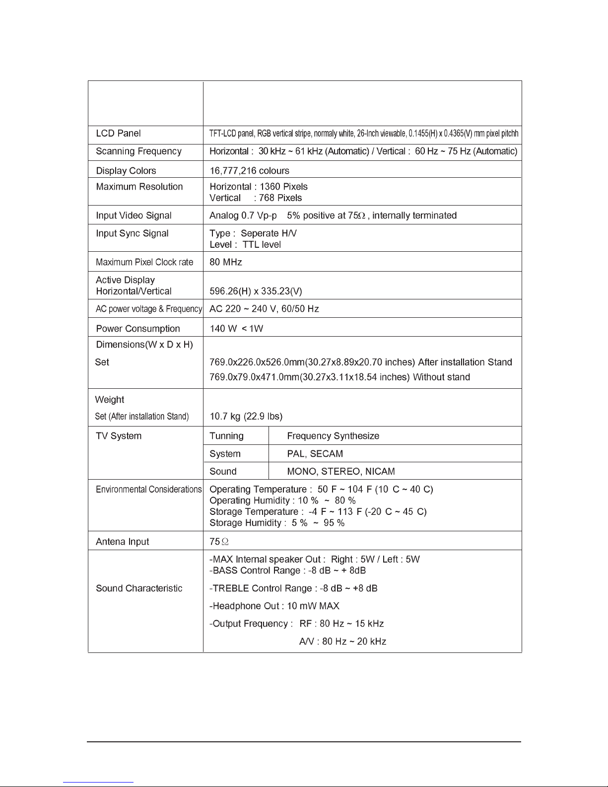
2-4 LE32S73BD Specifications
2 Product Specifications
2-5
LCD Panel
TFT-LCD panel, RGB vertical stripe, normaly white, 37-Inch viewable, 0.6 (H) x 0.6 (V) mm pixel pitch
Scanning Frequency Horizontal : 30 kHz ~ 61 kHz (Automatic) / Vertical : 60 Hz ~ 75 Hz (Automatic)
Display Colors 16,777,216 colours
Maximum Resolution Horizontal : 1360 Pixels
Vertical : 768 Pixels
Input Video Signal Analog 0.7 Vp-p ± 5% positive at 75
, internally terminated
Input Sync Signal Type : Seperate H/V
Level : TTL level
Maximum Pixel Clock rate
80 MHz
Active Display
Horizontal/Vertical 556.4 mm / 339.8 mm
AC power voltage & Frequency AC 220 ~ 240V, 50 ~ 60 Hz
Power Consumption 170 W
Dimensions(W x D x H)
Set 1026.5x330.0x698.8mm(40.4x13.0x27.5 inches) After installation Stand
1026.5x94.1x626.1mm(40.4x3.7x24.6 inches) Without stand
Weight
Set(After installation Stand) 21.5 kg (47.4 lbs)
TV System Tunning Frequency Synthesize
System PAL, SECEM
Sound MONO, STEREO, NICAM
Environmental Operating Temperature : 50°F ~ 104°F (10°C ~ 40°C)
Considerations Operating Humidity : 10 % ~ 80 %
Storage Temperature : -4°F ~ 113°F (-20°C ~ 45°C)
Storage Humidity : 5 % ~ 95 %
Antena Input 75
-MAX Internal speaker Out : Right : 5W / Left : 5W
-BASS Control Range : -8 dB ~ + 8dB
Sound Characteristic -TREBLE Control Range : -8 dB ~ +8 dB
-Headphone Out : 10 mW MAX
-Output Frequency : RF : 80 Hz ~ 15 kHz
A/V : 80 Hz ~ 20 kHz
Item
Description
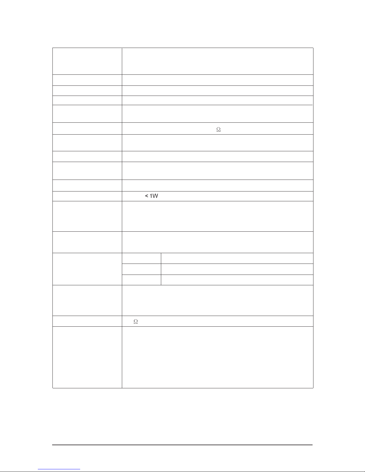
2-5 LE37S73BD Specifications

2 Product Specifications
2-6
LCD Panel
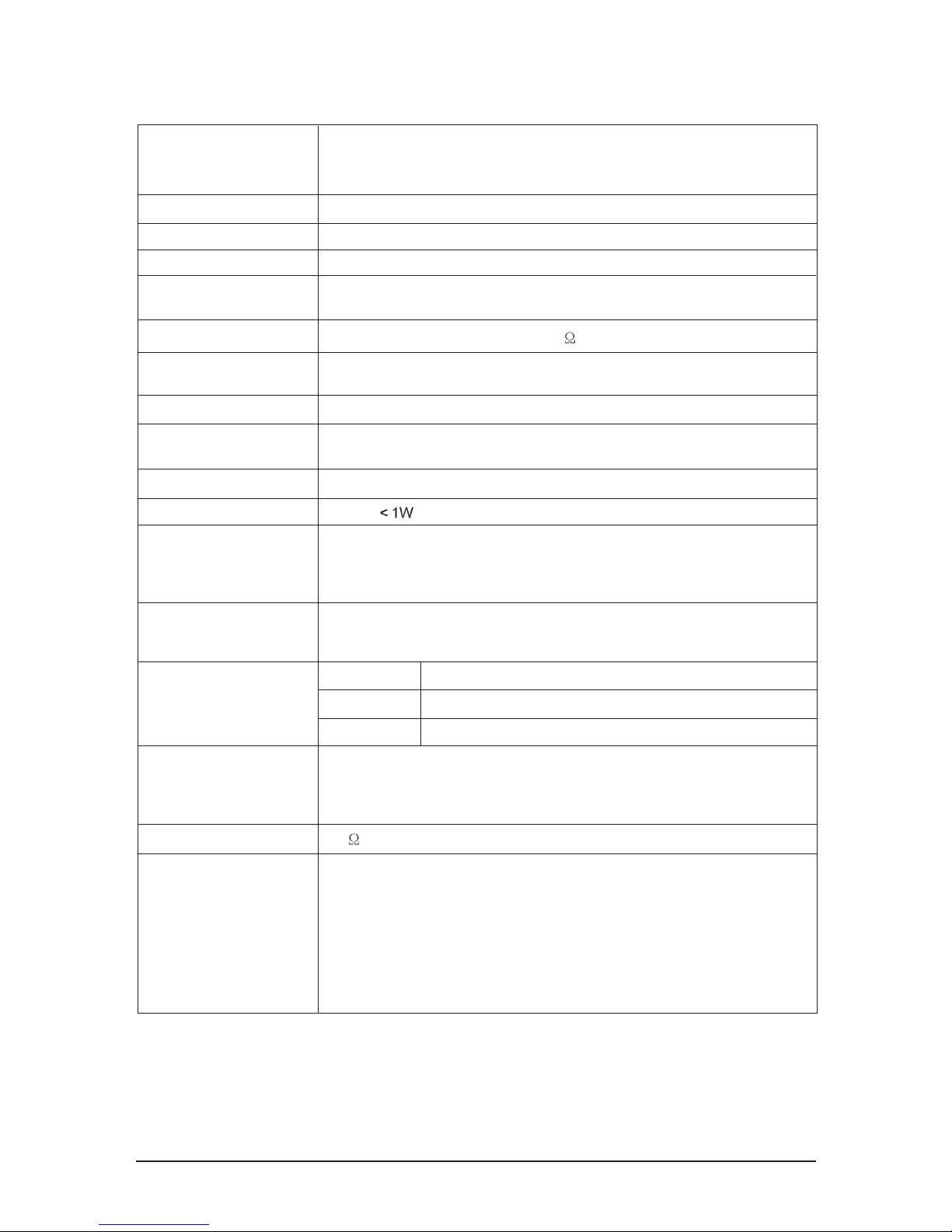
TFT-LCD panel, RGB vertical stripe, normaly white, 40-Inch viewable, 0.648(H) x 0.216(V) mm pixel pitch
Scanning Frequency Horizontal : 30 kHz ~ 61 kHz (Automatic) / Vertical : 60 Hz ~ 75 Hz (Automatic)
Display Colors 16,777,216 colours
Maximum Resolution Horizontal : 1360 Pixels
Vertical : 768 Pixels
Input Video Signal Analog 0.7 Vp-p ± 5% positive at 75 , internally terminated
Input Sync Signal Type : Seperate H/V
Level : TTL level
Maximum Pixel Clock rate
80 MHz
Active Display
Horizontal/Vertical 556.4 mm / 339.8 mm
AC power voltage & Frequency AC 220 ~ 240V, 50 ~ 60 Hz
Power Consumption 190 W
Dimensions(W x D x H)
Set
1100.5x330.0x732.5mm(43.32x12.99x28.83 inches) After installation Stand
1100.5x95.0x661.0mm(43.32x3.74x26.02 inches) Without stand
Weight
Set
(After installation Stand) 23.7 kg (52.2 lbs)
TV System Tunning Frequency Synthesize
System PAL, SECEM
Sound MONO, STEREO, NICAM
Environmental Considerations Operating Temperature : 50°F ~ 104°F (10°C ~ 40°C)
Operating Humidity : 10 % ~ 80 %
Storage Temperature : -4°F ~ 113°F (-20°C ~ 45°C)
Storage Humidity : 5 % ~ 95 %
Antena Input 75
-MAX Internal speaker Out : Right : 10W / Left : 10W
-BASS Control Range : -8 dB ~ + 8dB
Sound Characteristic -TREBLE Control Range : -8 dB ~ +8 dB
-Headphone Out : 10 mW MAX
-Output Frequency : RF : 80 Hz ~ 15 kHz
A/V : 80 Hz ~ 20 kHz
Item
Description
2-6 LE40S73BD Specifications
2 Product Specifications
2-7
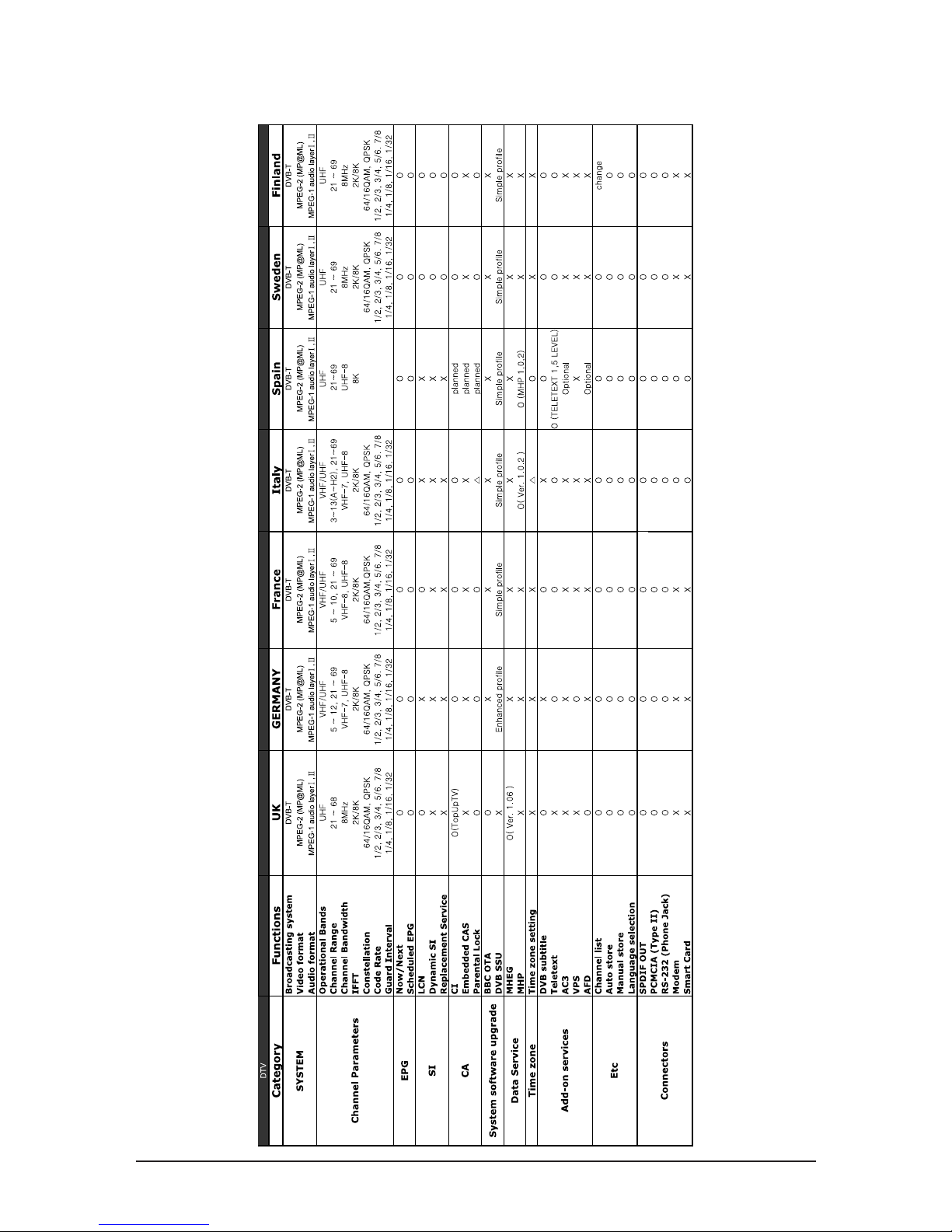
2-7 DTV Specification
2 Product Specifications
2-8
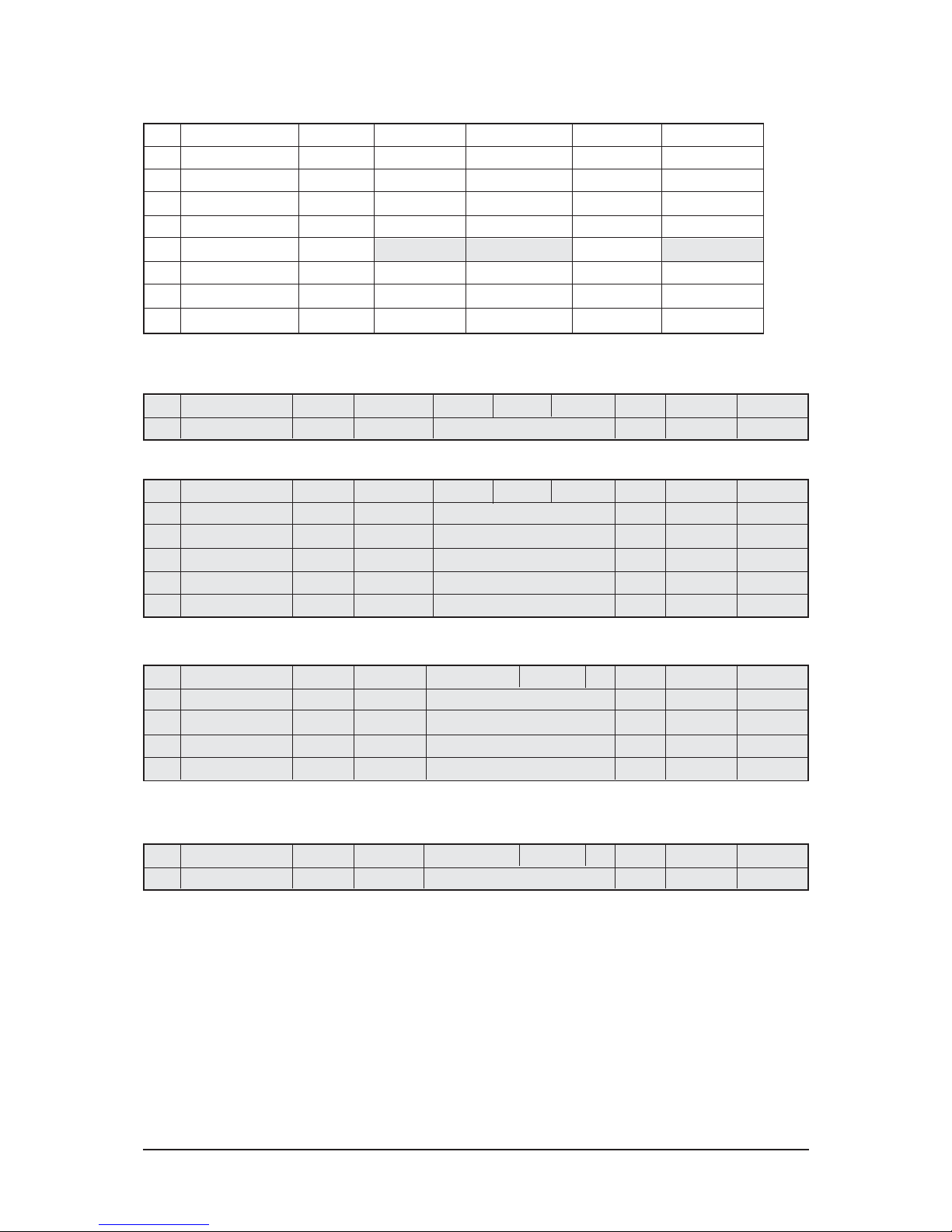
2-8 Spec Comparison
LE26R73BD/LE32R73BD/LE37R74BD/LE40R73BD
Model
Design
Frequency
Horizontal
Vertical
Display Color
30 ~ 61 kHz
60 ~ 75 Hz
16,777,216 colors
30 ~ 61 kHz
60 ~ 75 Hz
16,777,216 colors
PC Resolution
Maximum mode
Input Signal
Sync Signal
Video Signal
Power
Consumption
Normal
Power Saving
120W / 152W / 170W / 190W
< 1W
140W / 152W / 170W / 190W
< 1W
H/V Separate, TTL, P. or N.
0.7 Vp-p @ 75ohm
H/V Separate, TTL, P. or N.
0.7 Vp-p @ 75ohm
WXGA, 1360 x 768 @ 60 Hz WXGA, 1360 x 768 @ 60 Hz
LE27S73BD/LE32S73BD/LE37S73BD/LE40S73BD
2 Product Specifications
2-9
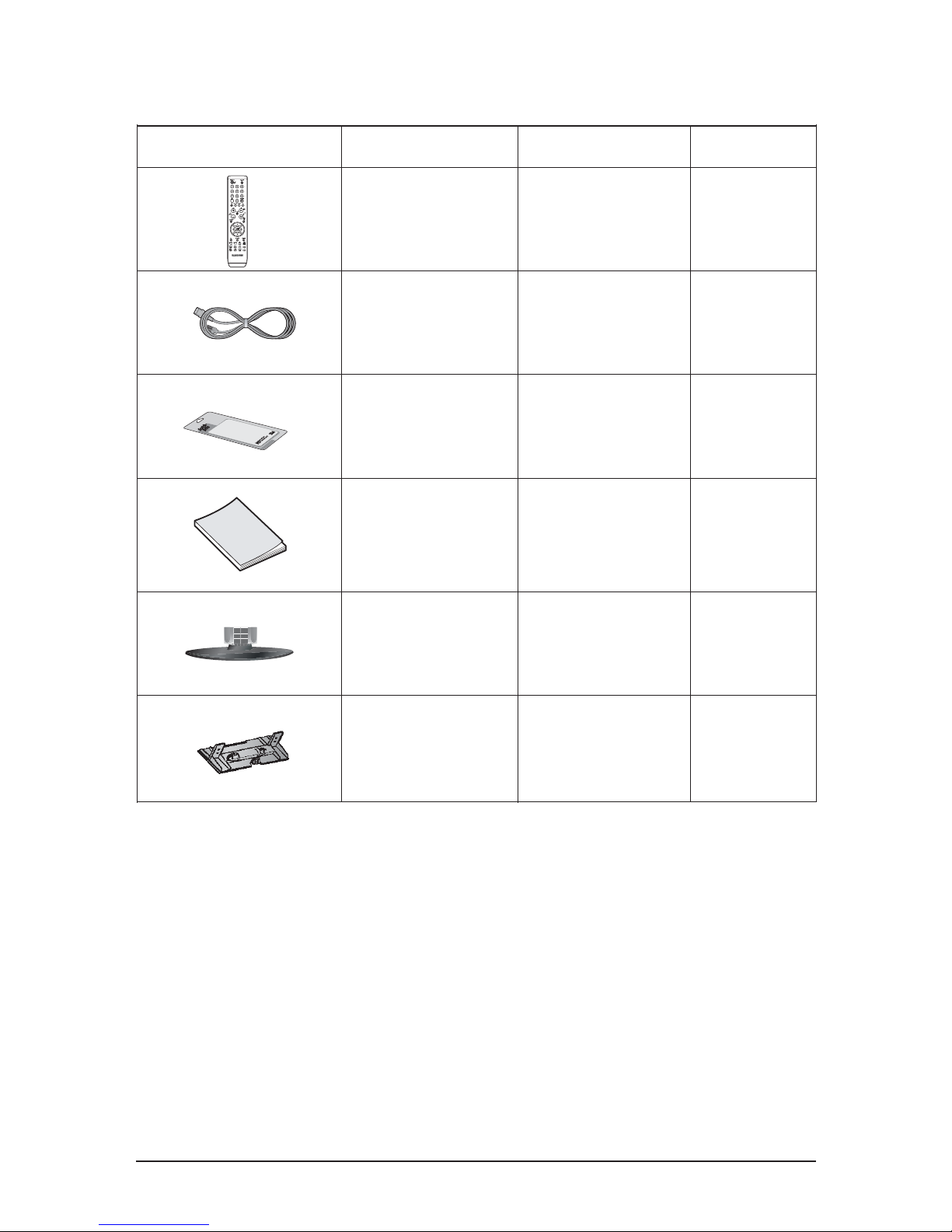
2-9 Option Specification
Item Item Name
Remote Control
&
Batteries (AAA x 2)
Power Cord
Cleaning Cloth
Owner's
Instructions
Stand
Cover-Bottom
BN59-00516A
BN59-00517A
(Only for Italy / Spain)
3903-000193
(Only for U.K)
3903-000145
BN63-001798A
BN68-01007K(U.K)
BN68-01007L
(Sweden/Finland)
BN68-01007M
(Italy/Spain)
27" : BN90-01005A
32" : BN90-00967A
37" : BN90-00966A
40" : BN90-00966A
27" : BN63-02415B
32" : BN63-02415B
37" : BN63-02416B
40" : BN63-02416B
Code.No Remark

Memo
2 Product Specifications
2-10

3 Alignments and Adjustments
3-1
3 Alignments and Adjustments
3-1 Ser vice Instr uction
1. Usually, a color TV-VCR needs only slight touch-up adjustment upon installation.
Check the basic characteristics such as height, horizontal and vertical sync.
2. Use the specified test equipment or its equivalent.
3. Correct impedance matching is essential.
4. Avoid overload. Excessive signal from a sweep generator might overload the front-end
of the TV. When inserting signal markers, do not allow the marker generator to distort
test result.
5. Connect the TV only to an AC power source with voltage and frequency as specified on
the backcover nameplate.
6. Do not attempt to connect or disconnect any wire while the TV is turned on. Make sure
that the power cord is disconnected before replacing any parts.
7. To protect aganist shock hazard, use an isolation transform.

3 Alignments and Adjustments
3-2
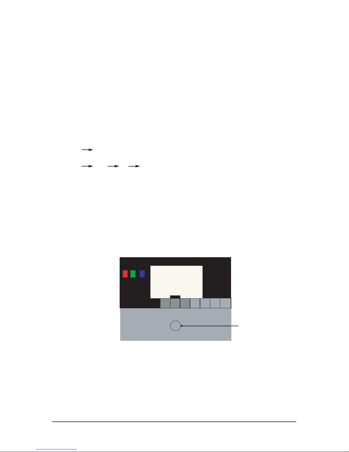
3-2 How to Access Service Mode
3-2-1 Entering Factory Mode
" "
- If you have Factory remote - control
Power OFF
PICTURE ON
DISPLAY
FACTORY
Power ON
INFO
MUTE
MENU
- The buttons are active in the service mode.
1. Remote - Control Key : Power, Arrow Up, Arrow Down, Arrow Left
Arrow Right, Menu, Enter, Number Key(0~9)
2. Function - Control Key : Power, CH +, CH -, VOL +, VOL -,
Menu, TV/VIDEO(Enter)
3-2-2 Panel Check
Specially for LE32R71B, You have to check Panel Maker Because of different adjustments as follows.
First of all, Check the label rating!
1) Label Rating File
2) If Panel Mark is "A", Set the factory mode indicating as follows.
* Option Byte
1. Inch Option 32"
2. Gamma 32"AUO
3. Panel Option AUO
Others are same shown below.
* If not printed you could consider S(sec) panel mark.

3 Alignments and Adjustments
3-3
3-3 Factory Data
1. Calibration
2. Option Table XXXX XXXX
3. White Balance
4. SVP-PX
5. Option Block
6. STV8257/STA323W
7. YC Delay
8. Adjust
9. I2C Check
10. W/B MOVIE
11. Checksum
12. Reset
13. Spread Spectrum
T-BRDMPEUD-0036 (Main Micom Ver)
T-CBGMPEUS-0004 (Sub Micom Ver)
Month / Day / Year / Hour / Min. / Sec.
3 Alignments and Adjustments
3-4
Inch Option
Gamma
Panel Option
2HDMI
Brt.Sensor
Energy Save
LBE/FBE
FRC (Micronas)
FRC2X
LNA
Carrier Mute
Language
Auto FM
High Deviation
TTX
TTX List
ACR
Dynamic CE
Dynamic Dimming
Turner TOP
TTX Group
Auto Power
Magazine LNA
Volume Mode
Shop Mode
Debug
Ch. Table
iDTV_Cntry
Dynamic Contrast
27"
CMO
CMO
Off
Off
On
Off
Off
Off
On
Off
English
On
Off
On
Flof
Off
On
On
8
Auto
On
Off
Small
Off
Off
SUWON
UK/Spain/Finland
Off
32"
Off/CMO
AMLCD_INT/
AUO_MVA
Off
Off
On
Off
Off
Off
On
Off
English
On
Off
On
Flof
Off
On
On
8
Auto
On
Off
Small
Off
Off
SUWON
UK/Spain/Finland
Off
37"
AUO
AUO
Off
Off
On
Off
Off
Off
On
Off
English
On
Off
On
Flof
Off
On
On
8
Auto
On
Off
Small
Off
Off
SUWON
UK/Spain/Finland
Off
40"
AMLCD
AMLCD_INT
Off
Off
On
Off
Off
Off
On
Off
English
On
Off
On
Flof
Off
On
On
8
Auto
On
Off
Small
Off
Off
SUWON
UK/Spain/Finland
Off
27/32/37/40
Off/AUO/CMO/AMLCD
AUO/CMO/AMLCD/AMLCD_INT/
Panel3/4/5/6
On/Off
On/Off
On/Off
On/Off
On/Off
On/Off
On/Off
On/Off
18 Language Support
On/Off
On/Off
On/Off
Flof/List
On/Off
Auto/West/East/Russian/Greek/
Turkey/Arabic/Farsian/Arab, Hbrw
On/Off
On/Off
Fix
On/Off
On/Off
UK/France/Germay/Sweden/
Italy/Spain/Finland
On/Off
2. Option Table XXXX XXXX
1. Calibration
1) AV Calibration
2) COMP Calibration
3) PC Calibration
4) HDMI Calibration
3 Alignments and Adjustments
3-5
3. White Balance
4. SVP-EX
1) Comb Filter
No
1
2
3
4
5
6
7
8
Item
Sub-Brightness
R-offset
G-offset
B-offset
Sub-Contrast
R-Gain
G-Gain
B-Gain
TV/AV
80
120
128
113
36
140
128
150
Component
115
130
128
128
32
129
128
129
PC
128
128
128
128
32
128
128
128
DVI(HDMI)
140
129
128
128
28
130
128
120
Range
0~255
0~255
0~255
0~255
0~63
0~255
0~255
0~255
No
1
Item
Y-Filter
EEPROM NTSC PAL
X
80h
SECAM Control IC RemarkRange
0~255
No
1
Item
Monitor
EEPROM
X
80h
Control IC RemarkRange
0~255
No
1
2
3
4
5
Item
Y-Peaking
Peaking Delay
Peaking Gain
Peaking Width
Peaking f0
EEPROM TV AV
X
X
X
X
X
80h
80h
80h
80h
80h
Component
Control IC RemarkRange
0~255
0~255
0~255
0~255
0~255
2) Peaking
No
1
2
3
4
Item
Y-NR-Off
C-NR-Off
Y-NR-ON
C-NR-ON
EEPROM
TV/AV/S-Video Component
X
X
X
X
80h
80h
80h
80h
PC
TV/AV/S-Video Component
PC
Control IC RemarkRange
0~255
0~255
0~255
0~255
3) NR
4) Delnterlace
3 Alignments and Adjustments
3-6
No
1
2
3
4
5
6
7
8
9
10
11
12
13
Item
TCD3 Contrast
TCD3 Brightness
TCD3 CR Saturation
TCD3 CB Saturation
TCD3 YC Delay
Analog Y offset
Analog PB offset
Analog PR offset
Analog Y Gain
Analog PB Gain
Analog PR Gain
Black Level Setting
Brightness (SVP)
EEPROM TV/AV/S-Video
78h
20h
78h
78h
00h
40h
80h
80h
D6h
FEh
FEh
78h
20h
78h
78h
00h
40h
80h
80h
D6h
FEh
FEh
AV Calibration(78h)
AV Calibration(20h)
78h
78h
00h
40h
80h
80h
D6h
FEh
FEh
78h
20h
78h
78h
00h
3
DTV Calibration(80h)
DTV Calibration(80h)
DTV Calibration(D6h)
FEh
FEh
PCComponent
00h
00h
DVI/HDMIRange
0~255
0~255
0~255
0~255
0~15
00~255
00~255
00~255
00~255
00~255
00~255
00~255
0~255
5) Picture Gain Adjust
No
1
2
3
4
5
6
Item
R-offset
G-offset
B-offset
R-Gain
G-Gain
B-Gain
EEPROM TV/AV/S-Video
PC Calibration(128)
PC Calibration(128)
PC Calibration(128)
PC Calibration(192)
PC Calibration(192)
PC Calibration(192)
151 (SC1 RGB)
151 (SC1 RGB)
151 (SC1 RGB)
123 (SC1 RGB)
123 (SC1 RGB)
123 (SC1 RGB)
XX
PC
Component
DVI/HDMIRange
00~255
00~255
00~255
00~255
00~255
00~255
5. MST9883
No
1
2
3
4
5
6
7
8
9
10
Item
FM-Prescale
NT-M-Prescale
SECAM-L-Prescale
NICAM-Prescale
AV-Prescale
12S_1 Prescale
12S_12 Prescale
Carrier Mute
Pilot High
Pilot Low
EEPROM PAL
20h
20h
22h
42h
1Ah
10h
10h
42h
14
7
Range
00~255
00~255
00~255
00~255
00~255
00~255
00~255
00~255
00~255
00~255
6. MSP34XX/44XX
3 Alignments and Adjustments
3-7
No
1
2
3
4
5
6
7
8
9
10
11
12
13
Item
RF PAL-B/G
RF PAL-D/K
PF PAL-I
RF SECAM-B/G
PF SECAM-D/K
RF SECAM-L/L'
RF NTSC 3.58
RF NTSC 4.43
AV PAL
AV SECAM
AV NTSC 3.58
AV NTSC 4.43
AV PAL60
EEPROM TV/AV/S-Video
77h
88h
66h
88h
77h
88h
66h
CCh
77h
BBh
66h
CCh
77h
PCComponent
88h
88h 88h
DVI/HDMIRange
00~255
00~255
00~255
00~255
00~255
00~255
00~255
00~255
00~255
00~255
00~255
00~255
00~255
7. YC Delay
8. Adjust
No
1
2
3
4
5
6
7
8
9
10
11
12
13
14
15
16
17
No
1
2
3
4
5
Item
Video Mute Time
Melody Volume
Ana_Dimm_Max
TTX Contrast
TTX Brightness
TTX Color
Dynamic Contrast
Dynamic Brightness
Dynamic Color
Dynamic Sharpness
Standard Contrast
Standard Brightness
Standard Color
Standard Sharpness
Movie Contrast
Movie Brightness
Movie Color
Movie Sharpness
Item
LNA PLUS
RFDB_1 Level
RFDB_2 Level
RFDB_3 Level
RFDB_4 Level
EEPROM
EEPROM
Component/PC/HDMI
Dynamic
Mode
Standard
Mode
Movie
Mode
P4 CVD2 0x7F
[07..00]
X
TV/AV/S-Video
10
5
FEH
50
50
50
100
50
55
75
80
50
50
50
70
50
25
45
TV/AV/S-Video
1
5
10
16
Component DVI/HDMIPC Control IC RemarkRange
0~20
0~100
0~100
0~100
0~100
0~100
0~100
0~100
0~100
0~100
0~100
0~100
0~100
0~100
0~100
0~100
Range
3 Alignments and Adjustments
3-8
9. 12C Check
10. Chip Debugger : OFF
11. Checksum XXXX XXXX
12. Reset
13. Spread Spectrum
1
2
3
4
Spectrum
Delta
Positive
Negative
ON
-3
8
2
3 Alignments and Adjustments
3-9
3-4 Ser vice Adjustment
3-4-1 White Balance - Calibration
If picture color is wrong, do calibration first.
Equipment : CA210, Patten : chess pattern
Execute calibration in Factory Mode
Source AV : PAL composite, Component : 1280*720/60Hz
PC : 1024*768/60Hz
3-4-2 White Balance - Adjustment
If picture color is wrong, check White Balance condition.
Equipment : CA210, Patten : Toshiba
Adjust W/B in Factory Mode
Sub brightness and R/G/B Offset controls low light region
Sub contrast and R/G/B Gain controls high light region
Source AV : PAL composite, Component : 1280*720/60Hz
HDMI[DVI] : 1280*720/60Hz
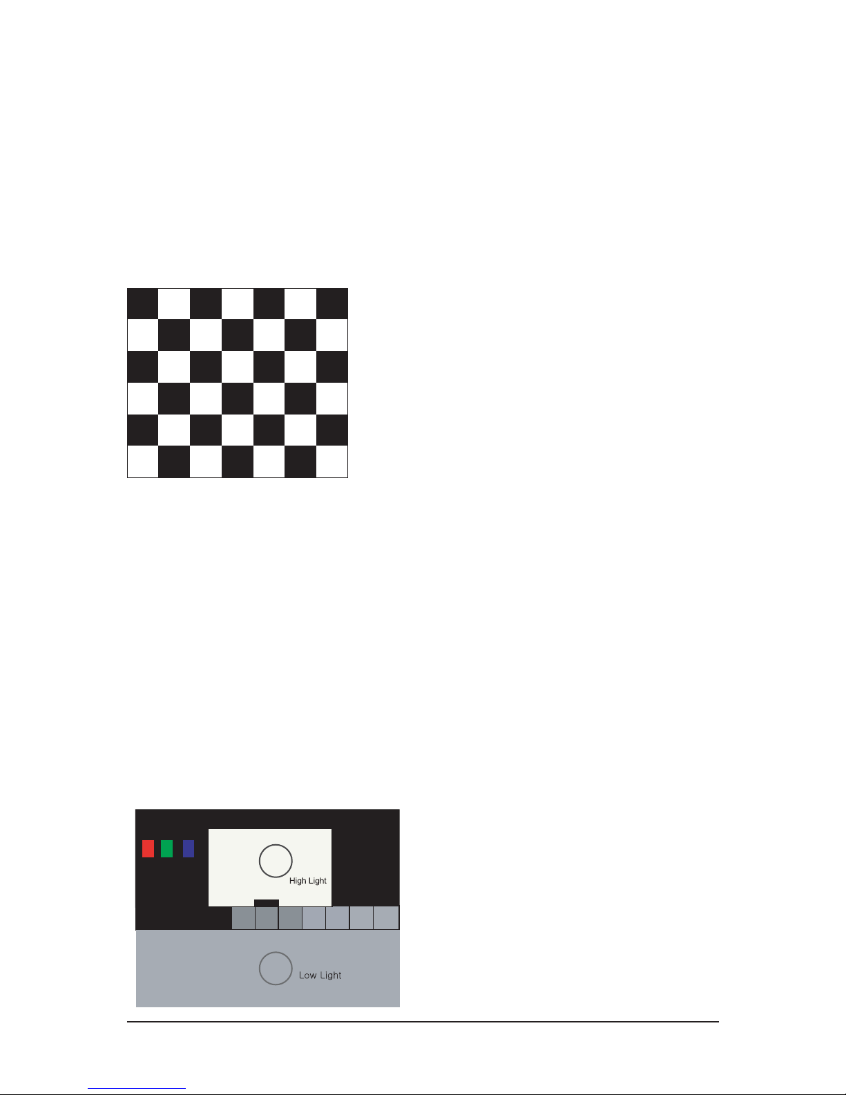
Toshiba Patten
[ Test Pattern : MSPG-945 Series Pattern #16 ]
*Color temperature
1500K +/-500, -6 ~-20 MPCD
*Color coordinate
H/L : 267/263 +/- 2 35.0 Ft +/- 2.0Ft
L/L : 270/260 +/- 3 1.5 Ft +/- 0.2Ft
( chess patten )
3 Alignments and Adjustments
3-10
3-4-3 Conditions for Measurement
1. On the basis of toshiba ABL pattern : High Light level (57 IRE)
- INPUT SIGNAL GENERATOR : MSPG-925LTH
* Mode NO 2 : 744X484@60 Hz
NO 6 : 1280X720@60 Hz
NO 21 : 1024X768@60 Hz
* Pattern NO 36 : 16 Color Pattern
NO 16 : Toshiba ABL Pattern
2. Optical measuring device : CA210 (FL)
Please use the MSPG-925 LTH generator for model
LE26M51B/LE32M51B/LE40M51B/LE46M51B
.
3-4-4 Method of Adjustment
1. Adjust the white balance of AV, Component and DVI Modes.
(AV Component)
a) Set the input to the mode in which the adjustment will be made
(RF DTV PC DVI).
* Input signal - VIDEO Mode : Model #2 (744*484 Mode), Pattern #16
- DTV,DVI Mode : Model #6 (1280*720 Mode), Pattern #16
- HDMI Mode: Model #6(1280*720 Mode), Pattern #16
b) Enter factory color control, confirm the data.
c) Adjust the low light. (Refer to table 1, 2 in adjustment position by mode)
- Adjust sub - Brightness to set the 'Y' value.
- Adjust red offset ('x') and blue offset ('y') to the color coordinates.
* Do not adjust green offset data.
d) Adjust the high light. (Refer to table 1, 2 in adjustment position by mode)
- Adjust red gain ('x') and blue gain ('y') to the color coordinates.
* Do not adjust the green gain and sub-contrast (Y) data.
Picture 4-2 Toshiba ABL Pattern
Low light
Measurement point
3 Alignments and Adjustments
3-11
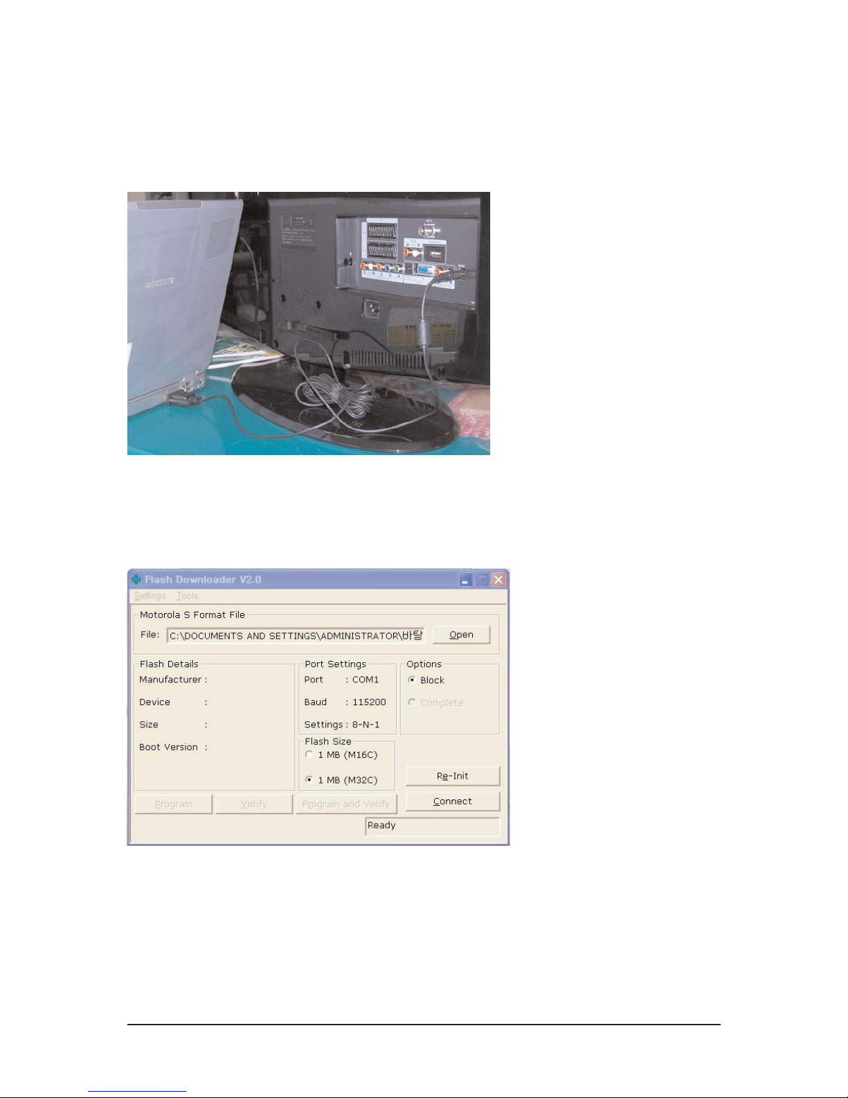
3-5 Software Upgrade
3-5-1 How to Update Flash ROM
1. Installthe Flash Downloader
ConnectSet(Service Jack)and Jig Cable to execute Program Update.
2. Flash Downloader program update
-Before Turning on the set,Click "connect"which is under of OSD Screen!
-Turn on the Set.
 Loading...