

Samsung iBG3026 Installation Manual


COPYRIGHT
This manual is proprietary to SAMSUNG Electronics Co., Ltd. and is protected by copyright.
No information contained herein may be copied, translated, transcribed or duplicated for any
commercial purposes or disclosed to third parties in any form without the prior written consent of
SAMSUNG Electronics Co., Ltd.
TRADEMARKS
Ubigate iBG3026 is registered trademarks of SAMSNUG Electronics.
All other company and product names may be trademarks of the respective companies with which
they are associated.
This manual should be read before the installation and operation, and the operator should
correctly install and operate the product by using this manual.
This manual may be changed for the system improvement, standardization and other technical reasons
without prior notice.
For further information on the updated manual or have a question for the content of manual, contact the
homepage below.
Homepage: http://www.samsungdocs.com
©2007~2008 SAMSUNG Electronics Co., Ltd. All rights reserved.

Ubigate iBG3026 Installation Manual
GENERAL USER INFORMATION
Radio Frequency Interference
This equipment has been tested and found to comply with the limits for a
Class A digital device, pursuant to Part 15 of the FCC Rules. These limits are
designed to provide reasonable protection against harmful interference when
the equipment is operated in a commercial environment. This equipment
generates, uses, and can radiate radio frequency energy and, if not installed
and used in accordance with the instruction manual, may cause harmful
interference to radio communications. Operation of this equipment in a
residential area is likely to cause harmful interference in which case the user
will be required to correct the interference at his own expense.
FCC Requirements
This equipment, the iBG3026, complies with Part 68 of the FCC rules and the
requirements adopted by the ATCA. On the left of this equipment is a label
that contains, among other information, a product identifier in the format
US: A3LIS00BiBG3026. If requested, this number must be provided to the
telephone company.
Unauthorized Modifications
Any changes or modifications performed on this equipment that are not
expressly approved in writing by SAMSUNG ELECTRONICS, CO., LTD.
could cause non-compliance with the FCC rules and void the user’s authority
to operate the equipment.
© SAMSUNG Electronics Co., Ltd.
I

GENERAL USER INFORMATION
Allowing this equipment to be operated in such a manner as not to
provide for proper answer supervision is a violation of Part 68 of the
FCC’s rules.
Telephone Connection Requirement
A plug and jack used to connect this equipment to the premises wiring and
telephone network must comply with the applicable FCC Part 68 rules and
requirements adopted by the ACTA. A compliant telephone cord and modular
plug is provided with this product. It is designed to connect to a compatible
modular jack that is also compliant. See installation instructions for details.
FCC Part 68
This equipment complies with Part 68 of the FCC rules. The FCC Part 68 label
is located on the left chassis panel. This label contains the FCC Registration
Number and Ringer Equivalence Number (REN) for this equipment.
If requested, this information must be provided to your telephone company.
Connection to the telephone network should be made by using standard
modular telephone jacks, type RJ-11C. The RJ-11C plug and/or jacks used
must comply with the FCC Part 68 rules.
CIRCUIT TYPE MODULE TYPE
LOOP START
LINE
DID LINE FXS-4M, FXS-24
E&M TIE LINE E&M-2M
FXO-4M
T1E1-2M
T1E1-4
T1E1-2M
T1E1-4
T1E1-2M
T1E1-4
FACILITY
INTERFACE CODE
02LS2
04DU9.DN
04DU9.1KN
04DU9.1SN
04DU9.1SN (PRI)
04DU9.DN
04DU9.1KN
04DU9.1SN
04DU9.1SN (PRI)
02RV2.T
04DU9.BN
04DU9.BN
TL11M
04DU9.BN
04DU9-BN
NETWORK
JACK
RJ11C
RJ48C
RJ48C
RJ11C
RJ48C
RJ48C
RJ45S
RJ48C
RJ48C
II
© SAMSUNG Electronics Co., Ltd.

Ubigate iBG3026 Installation Manual/Ed.01
Ringer Equivalence Number
The REN is used to determine the number of devices that may be connected to
a telephone line. Excessive RENs on a telephone line may result in the devices
not ringing in response to an incoming call. In most but not all areas, the sum
of RENs should not exceed five (5.0). To be certain of the number of devices
that may be connected to a line, as determined by the total RENs, contact the
local telephone company. For earlier products, the REN is separately shown
on the label.
Incidence of Harm
If this equipment, the iBG3026, causes harm to the telephone network, the
telephone company will notify you in advance that temporary discontinuance
of service may be required. But if advance notice is not practical, the telephone
company will notify the customer as soon as possible. Also, you will be advised
of your right to file a complaint with the FCC if you believe it is necessary.
Changes to Telephone Company Equipment or Facilities
The telephone company may make changes in its facilities, equipment,
operations or procedures that could affect the operation of the equipment.
If this happens, the telephone company will provide advance notice in order
for you to make necessary modifications to maintain uninterrupted service.
Service Center
If trouble is experienced with the iBG3026, please contact your local office of
SAMSUNG ELECTRONICS, CO., LTD. for repair or warranty information.
If the trouble is causing harm to the telephone network, the telephone
company may request that you remove the equipment from the network until
the problem is resolved.
Field Repairs
Only technicians certified on the iBG3026, are authorized by SAMSUNG
ELECTRONICS, CO., LTD. To perform system repairs. Certified technicians
may replace modular parts of a system to repair or diagnose trouble. Defective
modular parts can be returned to SAMSUNG ELECTRONICS, CO., LTD. for
repair.
© SAMSUNG Electronics Co., Ltd.
III

GENERAL USER INFORMATION
General
Connection to party line service is subject to state tariffs. Contact the state
public utility commission, public service commission or corporation
commission for information.
Equipment with Direct Inward Dialing (‘DID’)
ALLOWING THIS EQUIPMENT TO BE OPERATED IN SUCH A
MANNER AS NOT TO PROVIDE FOR PROPER ANSWER
SUPERVISION IS A VIOLATION OF PART 68 OF THE FCC’S RULES
PROPER ANSWER SUPERVISION IS WHEN:
A) This equipment returns answer supervision to the Public Switched
Telephone Network (PSTN) when DID calls are:
y Answered by the called station
y Answered by the attendant
y Routed to a recorded announcement that can be administered by the
Customer Premises Equipment (CPE) user.
y Routed to a dial prompt
B) This equipment returns answer supervision on all DID calls forwarded to
the PSTN.
y Permissible exceptions are:
y A call is unanswered
y A busy tone is received
y A reorder tone is received
Equal Access Requirements
This equipment is capable of providing user’s access to interstate providers of
operator services using access codes. Modification of this equipment by call
aggregators to block access dialing codes is a violation of the Telephone
Operator consumers Act of 1990.
IV
© SAMSUNG Electronics Co., Ltd.
Ubigate iBG3026 Installation Manual/Ed.01
Electrical Safety Advisory
Parties responsible for equipment requiring AC power should consider
including an advisory notice in their customer information suggesting the
customer use a surge arrestor. Telephone companies report that electrical
surges, typically lightning transients, are very destructive to customer terminal
equipment connected to AC power sources. This has been identified as a
major nationwide problem.
Music on Hold Warning
In accordance with US copyright laws, a license may be required from
the American Society of Composers, Authors and Publishers
(ASCAP) or other similar organizations if copyright music is
transmitted through the Music on Hold feature.
SAMSUNG ELECTRONICS, CO., LTD. hereby disclaims any liability
arising out of failure to obtain such a license.
DISA Warning
Lines that are used for the Direct Inward System Access feature must have the
disconnect supervision options provided by the telephone company.
As it is impossible to control who may access your DISA line it is
suggested that you do not turn this feature on unless you intend to
use it. If you do use this feature, it is good practice to frequently
change pass codes and periodically review your telephone records for
unauthorized use.
© SAMSUNG Electronics Co., Ltd.
V
GENERAL USER INFORMATION
Safety Warning
High touch current earth connection essential before making
telecommunication network connection.
Energy Hazard-careful treatment is needed.
Every wire for communication should be larger than 26 AWG.
Double pole/neutral fusing.
Underwriters Laboratories
The iBG3026 system has been tested to comply with safety standards in the
United States and Canada. This system is listed with Underwriters
Laboratories. The cUL Mark is separately shown on the label.
The following statement from Underwriters Labs applies to the Ubigate
iBG3026 System:
1.
Separation of TNV and SELV - Pluggable A:
INSTRUCTION: The separate protective earthing terminal provided on
this product shall be permanently connected to earth.
2.
Separation of TNV and SELV - Pluggable B:
INSTRUCTION: Disconnect TNV circuit connector (s) before
disconnecting power.’
VI
© SAMSUNG Electronics Co., Ltd.

Ubigate iBG3026 Installation Manual/Ed.01
3.
Warning to service personnel:
CAUTION: Double pole/neutral fusing.
4.
Telephone line cord:
CAUTION: To reduce the risk of fire, use only No. 26 AWG or larger
(e.g., 24 AWG) UL Listed or CSA Certified Telecommunication Line
Cord.
5.
Leakage currents due to ringing voltage - Earthing installation
instructions: ‘1.A supplementary equipment earthing conductor is to be
installed between the product or system and earth, that is, in addition to
the equipment earthing conductor in the power supply cord. 2.The
supplementary equipment earthing conductor may not be smaller in size
than the unearthed branch-circuit supply conductors. The equipment
earthing conductor is to be connected to the product at the terminal
provided, and connected to earth in a manner that ill retain the earth
connection when the power supply cord is unplugged. The connection to
earth of the supplementary earthing conductor shall be in compliance
with the appropriate rules for terminating bonding jumpers in Part K of
Article 250 of the National Electrical Code, ANSI/NFPA 70 and Article
10 of Part 1 of the Canadian Electrical Code, Part 1, C22.1. Termination
of the supplementary earthing conductor is permitted to be made to
building steel, to a metal electrical raceway system, or to any earthed
item that is permanently and reliably connected to the electrical service
equipment earthed. 3.Bare, covered, or insulated earthing conductors are
acceptable.
A covered or insulated conductor must have a continuous outer finish
that is either green, or green with one or more yellow stripes.’
6.
Safety Instructions - Rack Mount ‘Rack Mount Instructions -
The following or similar rack-mount instructions are included with the
installation instructions:
A) Elevated Operating Ambient - If installed in a closed or multi - unitrack
assembly, the operating ambient temperature of the rack environment
may be greater than room ambient. Therefore, consideration should be
given to installing the equipment in an environment compatible with
the maximum ambient temperature (Tma) specified by the
manufacturer.
© SAMSUNG Electronics Co., Ltd.
VII

GENERAL USER INFORMATION
B) Reduced Air Flow - Installation of the equipment in a rack should be
such that the amount of air flow required for safe operation of the
equipment is not compromised.
C) Mechanical Loading - Mounting of the equipment in the rack should be
such that a hazardous condition is not achieved due to uneven
mechanical loading.
D) Circuit Overloading - Consideration should be given to the connection
of the equipment to the supply circuit and the effect that overloading of
the circuits might have on overcurrent protection and supply wiring.
Appropriate consideration of equipment nameplate ratings should be
used when addressing this concern.
E) Reliable Earthing - Reliable earthing of rack-mounted equipment
should be maintained. Particular attention should be given to supply
connections other than direct connections to the branch circuit (e.g.,
use of power strips).’
VIII
© SAMSUNG Electronics Co., Ltd.

INTRODUCTION
Purpose
iBG3026™ Installation Manual provides instructions on installing the iBG3026,
including hardware descriptions, safety information, chassis installation,
module installation, interconnection, and troubling shooting descriptions.
Ubigate iBG3026 Installation Manual
Document Content and Organization
This manual is composed of five Chapters and two Annexes.
CHAPTER 1. iBG3026 Overview
y iBG3026 Chassis
y iBG3026 Hardware
CHAPTER 2. Pre-Installation Requirements
y Safety Recommendations
y General Site Requirements
y Inspecting the iBG3026
y Required Tools and Materials
CHAPTER 3. Router Installation
y Mounting the iBG3026
y Connecting the iBG3026
y Powering Up the iBG3026
© SAMSUNG Electronics Co., Ltd.
IX

INTRODUCTION
CHAPTER 4. Module and Internal Option Card Installation
y Safety Recommendations
y Modules and Internal Option Cards Types
y Port Numbering
y Connecting Modules and Optional Cards
y Installing Modules
CHAPTER 5. Components Installation
y Installing Power Supplies
y Changing the Fan Tray Assembly
y Modifying the Width of Network Module Slots
y Installing and Removing Voice Carrier Module
y Installing Compact Flash Memory Cards
y Installing DDR SDRAM SODIMM
ANNEX A. Specifications
ANNEX B. Cable Specifications
X
© SAMSUNG Electronics Co., Ltd.

Ubigate iBG3026 Installation Manual/Ed.01
Conventions
The following types of paragraphs contain special information that must be
carefully read and thoroughly understood. Such information may or may not
be enclosed in a rectangular box, separating it from the main text, but is
always preceded by an icon and/or a bold title.
WARNING
Provides information or instructions that the reader should follow in
order to avoid personal injury or fatality.
CAUTION
Provides information or instructions that the reader should follow in
order to avoid a service failure or damage to the system.
NOTE
Indicates additional information as a reference.
Information for Product and Technical Support
For questions regarding the product and technical supports:
http://www.samsungnetwork.com
Revision History
EDITION DATE OF ISSUE REMARKS
00 10. 2007. First edition
01 08. 2008. Add VPN-SSL module
© SAMSUNG Electronics Co., Ltd.
XI

INTRODUCTION
This page is intentionally left blank.
XII
© SAMSUNG Electronics Co., Ltd.
Ubigate iBG3026 Installation Manual
SAFETY CONCERNS
The purpose of the Safety Concerns section is to ensure the safety of users and prevent property
damage. Please read this document carefully for proper use.
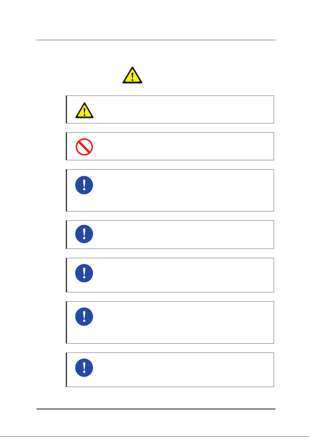
Symbols
Caution
Indication of a general caution.
Restriction
Indication for prohibiting an action for a product.
Instruction
Indication for commanding a specifically required action.
© SAMSUNG Electronics Co., Ltd.
XIII
SAFETY CONCERNS
Warning
Electric hazard exists. Verify the power is turned off. Do not work on
Invisible laser radiation may be emitted from disconnected fibers or
Laser radiation and EMI are present when the router cover panel is
WARNING
energized equipment. Working on energized equipment can result in
serious electrical shock.
connectors.
Do not stare into beams or view directly with optical instruments.
open.
To avoid electric shock, do not connect safety extra-low voltage
(SELV) circuits (as found in LAN ports) to telephone-network voltage
(TNV) circuits (as found in WAN ports).
When handling iBG3026 components, wear grounding wrist straps to
avoid ESD damage to the card. Do not directly touch the backplane
with your hand or any metal tool, or you could shock yourself.
AC power to the iBG3026 router is double fused. Fuses are installed
on both line and neutral conductors.
A neutral fuse failure may present a hazard to service personnel.
Disconnect the AC Line Cord or remove both AC fuses before
servicing the unit.
When you connect DC power to the Ubigate iBG3026, disconnect all
power sources before servicing.
XIV
© SAMSUNG Electronics Co., Ltd.
Ubigate iBG3026 Installation Manual/Ed.01
Caution
CAUTION
As a general safety precaution, be sure to provide DC power through
a circuit breaker on the equipment rack.
Do not place any items that weigh more than 4.5 kg on top of the
chassis, and do not stack routers on a desktop.
This equipment must be installed and maintained by properly trained
service personnel. Make sure the proper electrical service is available
before plugging this unit in and turning it on. Disconnect the
telecommunications lines before unplugging the main power connector.
Practice good safety habits. Use two people to mount the router into a
rack.
To comply with the Telcordia GR-1089 NEBS standard for
electromagnetic compatibility and safety, connect only to intra-building
or non-exposed wiring or cabling.
SFPs include a laser transceiver on the fiber-optic uplink port.
Use of controls or adjustments of performance or procedures other
than those specified in this manual may result in hazardous radiation
exposure.
To prevent damage to the iBG3026, do not remove a Compact Flash
memory card from the chassis while it is being accessed (when the
CF LED is blinking).
© SAMSUNG Electronics Co., Ltd.
XV

SAFETY CONCERNS
This page is intentionally left blank.
XVI
© SAMSUNG Electronics Co., Ltd.

Ubigate iBG3026 Installation Manual
TABLE OF CONTENTS
GENERAL USER INFORMATION I
Radio Frequency Interference ........................................................................................ I
FCC Requirements......................................................................................................... I
Music on Hold Warning..................................................................................................V
DISA Warning ................................................................................................................V
Safety Warning .............................................................................................................VI
Underwriters Laboratories ............................................................................................VI
INTRODUCTION IX
Purpose ........................................................................................................................IX
Document Content and Organization ...........................................................................IX
Conventions..................................................................................................................XI
Information for Product and Technical Support.............................................................XI
Revision History............................................................................................................XI
SAFETY CONCERNS XIII
Symbols...................................................................................................................... XIII
Warning ..................................................................................................................... XIV
Caution ....................................................................................................................... XV
CHAPTER 1. iBG3026 Overview 1
iBG3026 Chassis ................................................................................................................2
iBG3026 Front Panel ..................................................................................................... 2
iBG3026 Main Board View............................................................................................. 4
iBG3026 Hardware.............................................................................................................. 7
Modules and Internal Option Cards ............................................................................... 7
Memory..........................................................................................................................8
Power ............................................................................................................................ 8
Ventilation...................................................................................................................... 9
© SAMSUNG Electronics Co., Ltd.
XVII

TABLE OF CONTENTS
Real-Time Clock and NVRAM........................................................................................9
CHAPTER 2. Pre-Installation Requirements 11
Safety Recommendations................................................................................................ 11
Class 1 Laser Product.................................................................................................. 12
Cover Panels ...............................................................................................................12
Electrostatic Discharge (ESD) Warning ....................................................................... 12
Best Practices-Safety...................................................................................................13
Safety Instructions on Rack Mounting the Router........................................................ 13
Fuse Replacement....................................................................................................... 14
PoE Requirements....................................................................................................... 14
General Maintenance Guidelines................................................................................. 14
General Site Requirements.............................................................................................. 15
Site Preparation ........................................................................................................... 15
Environment................................................................................................................. 15
Power Requirements ...................................................................................................16
Inspecting the iBG3026 .................................................................................................... 17
Required Tools and Materials .......................................................................................... 18
Cables..........................................................................................................................18
Tools ............................................................................................................................18
Materials ...................................................................................................................... 18
CHAPTER 3. Router Installation 19
Mounting the iBG3026...................................................................................................... 19
Desktop Installation...................................................................................................... 19
Rack Mount Installation................................................................................................ 20
Closed Rack Installation Recommendations................................................................ 24
Grounding the iBG3026 ............................................................................................... 25
Connecting the iBG3026 .................................................................................................. 26
LAN Interface............................................................................................................... 26
Management Interface................................................................................................. 27
Console Interface......................................................................................................... 27
Auxiliary Interface (for Remote Access)....................................................................... 28
Powering Up the iBG3026 ................................................................................................31
iBG3026 Power Prerequisites...................................................................................... 31
Applying Power............................................................................................................ 34
XVIII
© SAMSUNG Electronics Co., Ltd.

Ubigate iBG3026 Installation Manual/Ed.01
CHAPTER 4. Module and Internal Option Card Installation 35
Safety Recommendations................................................................................................ 35
Modules and Internal Option Cards Types..................................................................... 37
Port Numbering ................................................................................................................ 39
LAN Ports .................................................................................................................... 39
WAN Ports................................................................................................................... 41
Mini Modules ............................................................................................................... 43
Port Numbering Examples........................................................................................... 44
Connecting Modules and Option Cards ......................................................................... 45
Internal Option Cards .................................................................................................. 45
WAN Interface Module................................................................................................. 46
LAN Interface Modules ................................................................................................ 55
Voice Modules ............................................................................................................. 64
Installing Modules ............................................................................................................ 70
Installing Main Module................................................................................................. 70
Installing Network Modules.......................................................................................... 71
Installing Mini Modules ................................................................................................ 73
Installing LMG-44/LMGP-44 Module............................................................................ 74
Installing ESG-8/ESF-10 Module................................................................................. 76
Installing Internal Option Card ..................................................................................... 77
Installing SFP Modules ................................................................................................ 78
CHAPTER 5. Components Installation 79
Installing Power Supplies................................................................................................ 79
Changing the Fan Tray Assembly ................................................................................... 82
Modifying the Width of Network Module Slots............................................................... 84
Installing and Removing Voice Carrier Module.............................................................. 84
Installing Compact Flash Memory Cards ....................................................................... 85
Installing DDR SDRAM SODIMM ..................................................................................... 86
ANNEX A. Specifications 89
Ubigate iBG3026 Product Specifications ....................................................................... 89
Interface ............................................................................................................................ 91
© SAMSUNG Electronics Co., Ltd.
XIX

TABLE OF CONTENTS
E1 WAN Interface ........................................................................................................91
T1 WAN Interface ........................................................................................................91
Ethernet LAN Interface ................................................................................................92
ANNEX B. Cable Specifications 93
Console Port (Main Board) Cable.................................................................................... 93
Auxiliary Port (Main Board) Cable................................................................................... 94
BRI-2U Mini Module Cable ............................................................................................... 95
BRI-2ST Mini Module Cable ............................................................................................. 96
ESG-8, LMG-20, LMF-20, LMP-20, LMG-44, LMGP-44 Module Cable............................ 97
T1E1-4, T1E1-2M Module Cable....................................................................................... 98
HSSI-1 Module Cable........................................................................................................ 99
HSSI-1 Module Cable (Null Modem Case)..................................................................... 100
FXS-24 Module Cable ..................................................................................................... 101
E&M-2M Module Cable ................................................................................................... 102
FXO-4M, FXS-4M Module Cable..................................................................................... 103
XX
© SAMSUNG Electronics Co., Ltd.

Ubigate iBG3026 Installation Manual/Ed.01
LIST OF FIGURES
Figure 1.1 iBG3026 Front View................................................................................... 2
Figure 1.2 iBG3026 Rear View ................................................................................... 5
Figure 2.1 Air flow of the iBG3026 ............................................................................ 15
Figure 3.1 Mounting Brackets ................................................................................... 20
Figure 3.2 Bracket Installation for Front Mounting .................................................... 21
Figure 3.3 Bracket Installation for Rear Mounting ..................................................... 22
Figure 3.4 Bracket Installation for Center Mounting with Rear Panel Forward.......... 22
Figure 3.5 Rack mounting the Router ....................................................................... 23
Figure 3.6 Ground Connection on iBG3026.............................................................. 25
Figure 3.7 Connecting LAN Cables........................................................................... 26
Figure 3.8 Connecting Management Cable............................................................... 27
Figure 3.9 Connecting Console Cable ...................................................................... 28
Figure 3.10 Remotely Accessing an iBG3026 Router ............................................... 28
Figure 3.11 Connecting Auxiliary Cable .................................................................... 30
Figure 3.12 AC Power Connection............................................................................ 31
Figure 3.13 AC Power with PoE Connection............................................................. 32
Figure 3.14 DC Power with PoE Connection ............................................................ 33
Figure 4.1 Modules and Internal Option Card ........................................................... 38
Figure 4.2 Main Board LAN Port Numbering............................................................. 39
Figure 4.3 Ethernet Switch Gigabit Module Port Numbering..................................... 40
Figure 4.4 20-port Network Module Port Numbering................................................. 40
Figure 4.5 44-port Network Module Port Numbering................................................. 41
Figure 4.6 2-Port Mini Module Port Numbering......................................................... 41
Figure 4.7 4-Port Mini Module Port Numbering......................................................... 41
Figure 4.8 1-Port WAN Module Port Numbering ....................................................... 42
Figure 4.9 4-Port WAN Module Port Numbering ....................................................... 42
Figure 4.10 Main Board Mini Module Ports Numbering............................................. 43
Figure 4.11 Voice Carrier and Mini Module Ports Numbering.................................... 43
Figure 4.12 VPN-A, VPN-SSL Internal Option Cards................................................ 45
Figure 4.13 VoP-32, 64, 128 Internal Option Cards .................................................. 45
Figure 4.14 BRI-2ST Mini Module............................................................................. 46
Figure 4.15 Connecting BRI-2ST Mini Module.......................................................... 47
Figure 4.16 BRI-2U Mini Module ............................................................................... 47
© SAMSUNG Electronics Co., Ltd.
XXI

TABLE OF CONTENTS
Figure 4.17 Connecting BRI-2U Mini Module ............................................................ 48
Figure 4.18 T1E1-2M Mini Module ............................................................................49
Figure 4.19 Connecting the T1E1-2M Mini Module ................................................... 50
Figure 4.20 T1E1-4 Network Module.........................................................................50
Figure 4.21 Connecting the T1E1-4 Network Module ............................................... 51
Figure 4.22 WTE-4S Network Module....................................................................... 52
Figure 4.23 Connecting the WTE-4S Network Module .............................................. 52
Figure 4.24 HSSI-1 Network Module......................................................................... 53
Figure 4.25 Connecting the HSSI-1 Network Module ................................................ 53
Figure 4.26 WT3-1C Module ..................................................................................... 54
Figure 4.27 Connecting the WT3-1C Network Module.............................................. 54
Figure 4.28 ESG-8 Network Module..........................................................................56
Figure 4.29 Connecting the ESG-8 Network Module ................................................56
Figure 4.30 ESF-10 Network Module ........................................................................ 57
Figure 4.31 Connecting the ESF-10 Network Module ............................................... 58
Figure 4.32 LMG-20 Network Module .......................................................................59
Figure 4.33 Connecting the LMG-20 Network Module ..............................................59
Figure 4.34 LMF-20 Network Module........................................................................ 60
Figure 4.35 Connecting the LMF-20 Network Module............................................... 60
Figure 4.36 LMP-20 Network Module........................................................................ 61
Figure 4.37 Connecting the LMP-20 Network Module............................................... 61
Figure 4.38 LMG-44 Network Module .......................................................................62
Figure 4.39 Connecting the LMG-44 Network Module ..............................................62
Figure 4.40 LMGP-44 Network Module ..................................................................... 63
Figure 4.41 Connecting the LMGP-44 Network Module ............................................ 63
Figure 4.42 VCU-A Network Module ......................................................................... 64
Figure 4.43 FXO-4M Mini Module ............................................................................. 64
Figure 4.44 Connecting the FXO-4M Mini Module .................................................... 65
Figure 4.45 FXS-4M Mini Module.............................................................................. 65
Figure 4.46 Connecting the FXS-4M Mini Module..................................................... 66
Figure 4.47 E&M-2M Mini Module............................................................................. 66
Figure 4.48 Connecting the E&M-2M Mini Module.................................................... 67
Figure 4.49 FXS-24 Network Module ........................................................................68
Figure 4.50 Connecting the FXS-24 Network Module ............................................... 69
Figure 4.51 Install the Main Board.............................................................................70
Figure 4.52 Preparing a Network Module slot for Module insertion........................... 71
Figure 4.53 Aligning the new Network Module .......................................................... 72
Figure 4.54 Preparing a Mini module slot for module insertion ................................. 73
Figure 4.55 Aligning the new Mini module................................................................. 73
XXII
© SAMSUNG Electronics Co., Ltd.

Ubigate iBG3026 Installation Manual/Ed.01
Figure 4.56 Removing the Mid-span Support............................................................ 74
Figure 4.57 Aligning the new Network Module.......................................................... 75
Figure 4.58 Preparing a ESG-8/ESF-10 Module slot for Module insertion ................ 76
Figure 4.59 Aligning the new Network Module.......................................................... 76
Figure 4.60 Installing the Internal Option Card.......................................................... 77
Figure 4.61 Installing SFP Modules .......................................................................... 78
Figure 4.62 Removing SFP Modules ........................................................................ 78
Figure 5.1 AC Power Supply..................................................................................... 79
Figure 5.2 AC Power Supply with POE..................................................................... 80
Figure 5.3 DC Power Supply with POE..................................................................... 80
Figure 5.4 Installing a Power Supply ......................................................................... 81
Figure 5.5 iBG3026 Router Front Panel.................................................................... 82
Figure 5.6 Removing/Replacing the Mid-span Support............................................. 84
Figure 5.7 Inserting a Voice Carrier Module.............................................................. 84
Figure 5.8 Removing a Compact Flash Memory Card .............................................. 85
Figure 5.9 Removing a DDR SDRAM SODIMM module........................................... 86
Figure A.1 Console Port Cable.................................................................................. 93
Figure A.2 Auxiliary Port Cable ................................................................................. 94
Figure A.3 BRI-2U Mini Module Cable ...................................................................... 95
Figure A.4 BRI-2ST Module Cable ............................................................................ 96
Figure A.5 ESG-8, LMG-20, LMF-20, LMP-20, LMG-44 Module Cable .................... 97
Figure A.6 T1E1-4, T1E1-2M Module Cable ............................................................. 98
Figure A.7 HSSI-1 Module Cable .............................................................................. 99
Figure A.8 HSSI-1 Module Cable (Null Modem Case) ............................................ 100
Figure A.9 FXS-24 Module Cable ........................................................................... 101
Figure A.10 E&M-2M Module Cable........................................................................ 102
Figure A.11 FXO-4M, FXS-4M Module Cable ......................................................... 103
© SAMSUNG Electronics Co., Ltd.
XXIII

TABLE OF CONTENTS
This page is intentionally left blank.
XXIV
© SAMSUNG Electronics Co., Ltd.

Ubigate iBG3026 Installation Manual
CHAPTER 1. iBG3026 Overview
Chapter1 provides an overview of the Ubigate iBG3026 router.
This chapter provides an overview of the iBG3026 router including information
about front and back panels for iBG3026 router. In addition, information is
provided about cable connection ports and panel components.
The iBG3026 router is a modular WAN/LAN router. It is a 2U rack-mount
unit with redundant power supplies and a number of slots for interchangeable
interface modules. The router is a WAN/LAN router that supports WAN/LAN,
multi-protocol routing. An optional IPSec VPN and SSL VPN option cards
provide high-performance encryption and decryption services for the core
router.
In addition, an Ethernet switch/route Subsystem and a Voice Subsystem may
be incorporated into the router by adding appropriate optional cards and
modules. These support multi-Gigabit Ethernet Layer-2 switching, Layer-3 IP
routing, and VoIP processing for up to 256 voice calls, respectively.
© SAMSUNG Electronics Co., Ltd.
1
CHAPTER 1. iBG3026 Overview
iBG3026 Chassis
This section describes front and back-panel components of the iBG3026 router.
Additional information is also provided about external cables, wiring, and
connection points.
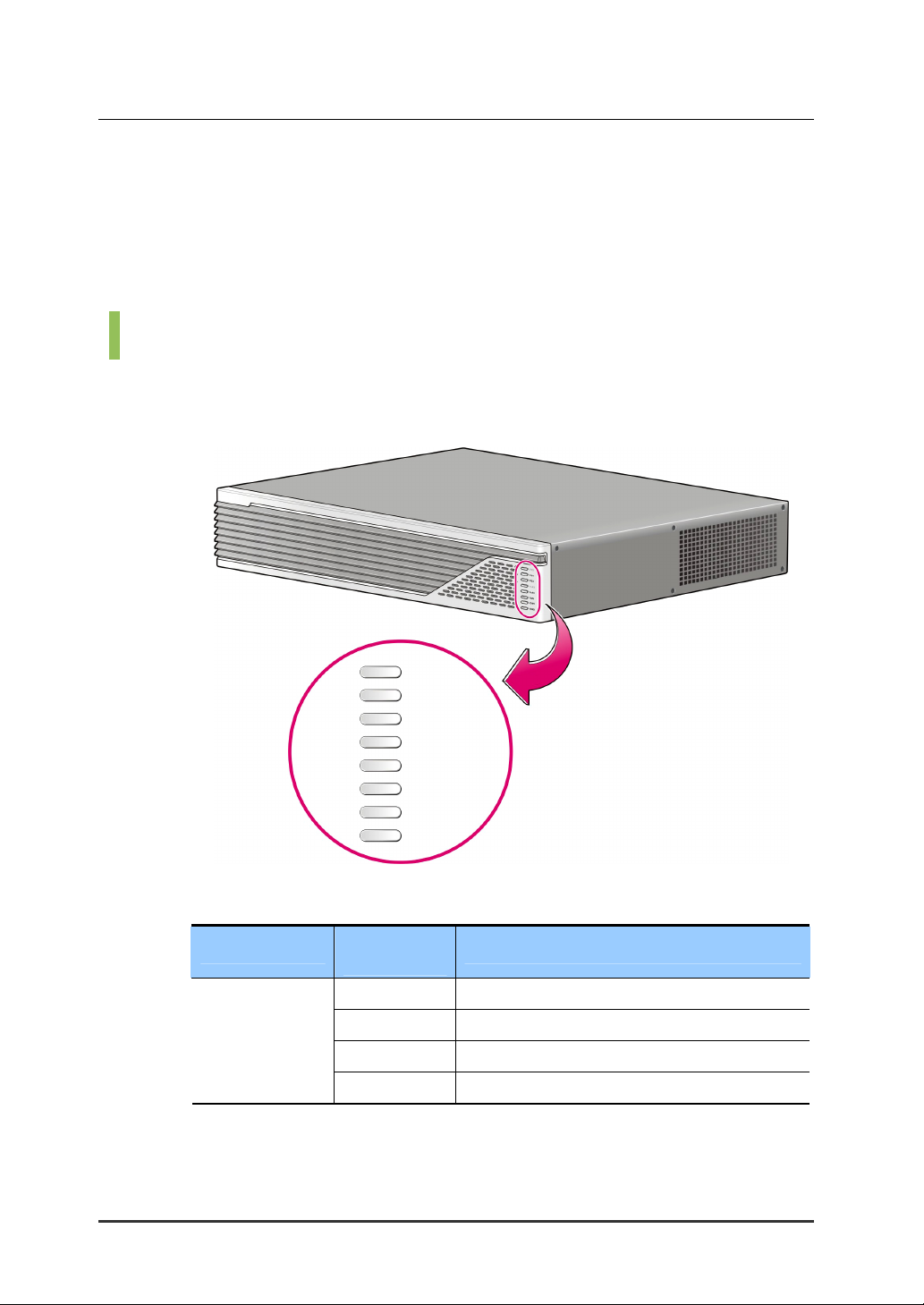
iBG3026 Front Panel
The front panel of the iBG3026 provides status of the router’s performance
and operation by using LEDs. Proper LED status is shown as following.
LED
SYS
(Router Power)
SYS
PSU1
PSU2
PoE1
PoE2
FAN
VoP
VPN
Figure 1.1 iBG3026 Front View
Indication
& Color
Solid green System is operating normally.
Blinking green Running ROM monitor with no errors detected.
Amber Router is receiving power but malfunctioning.
Off Router is not receiving power.
Description
2
© SAMSUNG Electronics Co., Ltd.

Ubigate iBG3026 Installation Manual/Ed.01
(Continued)
LED
PSU1
(Power Supply 1)
PSU2
(Power Supply 2)
PoE1
(PoE Power 1)
PoE2
(PoE Power 2)
FAN
Indication
& Color
Solid green
Power supply 1 installed and operating normally.
Description
Amber Power supply 1 installed and powered off, or
fault condition detected.
Off Power supply 1 not present.
Solid green
Power supply 2 installed and operating normally.
Amber Power supply 2 installed and powered off, or
fault condition detected.
Off Power supply 2 not present.
Solid green -48 V power module 1 installed and operating
normally.
Amber -48 V power module 1 installed and powered
off, or fault condition detected.
Off -48 V power module 1 not present.
Solid green -48 V power module 2 installed and operating
normally.
Amber -48 V power module 2 installed and powered
off, or fault condition detected.
Off -48 V power module 2 not present.
Solid green Fan is operating properly
VoP
VPN
© SAMSUNG Electronics Co., Ltd.
Amber Fan present with failure
Solid green VoP card present and enabled.
Amber or Red VoP card present with failure.
Off VoP card not present
Solid green VPN card present and enabled.
Amber or Red VPN card present with failure.
Off VPN card not present
3
CHAPTER 1. iBG3026 Overview
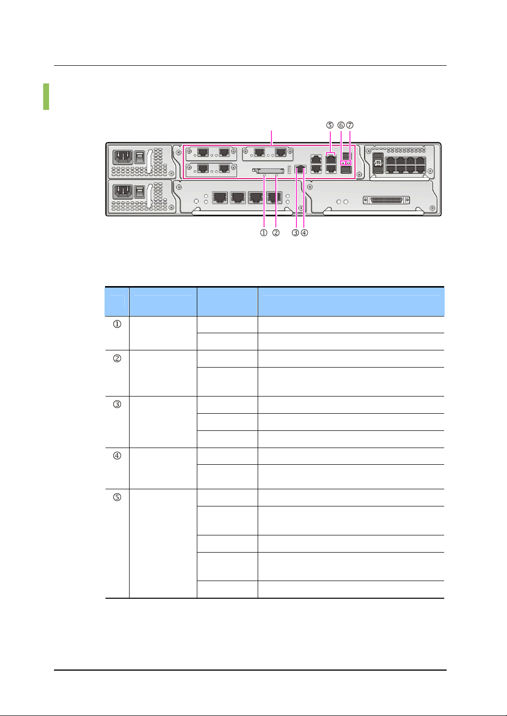
iBG3026 Main Board View
Main Board LED Description
No. LED
SYS RDY
Indication
& Color
Solid green The module’s power is normal status.
Main Board
Description
CF
Management
port Left LED
(Link)
Management
port Right LED
(Speed)
UTP GbE Port
LED
Off Power fail or removal status.
Solid green Compact Flash being accessed
Off Compact Flash not mounted or not being
accessed.
Solid Green The management link connected.
Green Blink Link connect and transmit data
Off The management port is not connected.
Solid Amber The link speed is 100Mbps.
Off The link speed is 10Mbps.
Solid Green Link is established with speed 10/100 Mbps.
Green Blink Blinking green indicates transmit/receive
activity with speed 10/100 Mbps.
Solid Amber Link is established with speed 1000 Mbps.
Amber Blink Blinking amber indicates transmit/receive
activity with speed 1000 Mbps.
Off Link fail or no connect.
4
© SAMSUNG Electronics Co., Ltd.
 Loading...