

Samsung ELSR362-00004 Installation Manual
Australia (Eng.) 05/2015. Rev1.1
Installation Manual
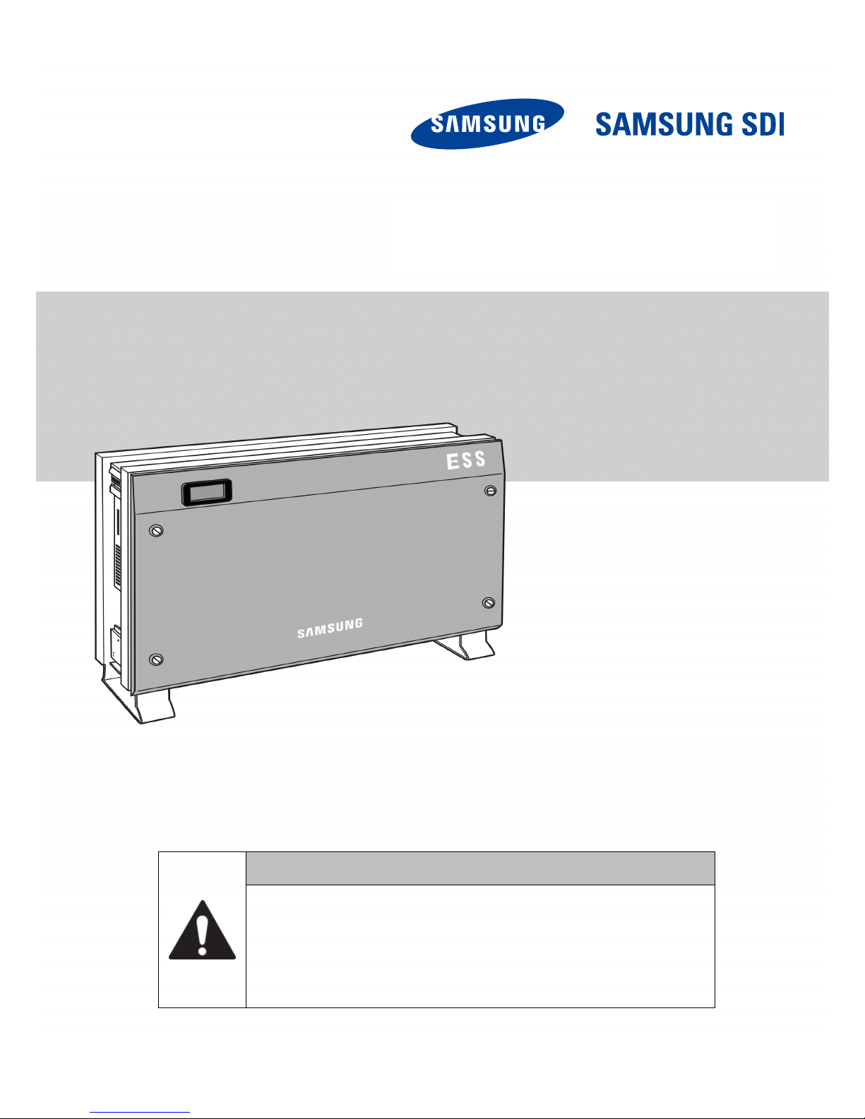
RES 3.6 kWh All In One
CAUTION
Do not operate with other components not approved by the ESS systems.
(Connecting other products in parallel to Samsung SDI's products may result in
abnormal operation.)
The internet connection is required to use all functions of the ESS system.
If you have a problem, please contact the installer.
The Specications of the product may be modied without prior notice to improve
product qu
ality.
ELSR362-00004

Table of Contents
Table of Contents
Table of Contents ......................................................................................................... i
Table of Tables ........................................................................................................... iv
Table of Figures ........................................................................................................... v
1. About this Manual ................................................................................................. 1
1.1 Valid Range ................................................................................................................................................. 1
1.2 Targ e t Group .............................................................................................................................................. 1
1.3 Manual Storage ......................................................................................................................................... 1
1.4 Symbols Used ............................................................................................................................................ 1
2. Safety ...................................................................................................................... 4
2.1 Intended Use .............................................................................................................................................. 4
2.2 Safety Precautions .................................................................................................................................... 6
2.3 Product Overview ..................................................................................................................................... 7
2.3.1 Basic Specifications .................................................................................................................... 8
2.3.2 Grounding the PV Inverter ....................................................................................................... 8
3. Package Removal and Inspection ......................................................................... 9
3.1 Package Removal and Tray Assembly ................................................................................................. 9
3.1.1 Removing the Enclosure Package ......................................................................................... 9
3.1.2 Removing the Battery Tray Package................................................................................... 10
3.1.3 Checking Components on the Packing List ...................................................................... 11
3.1.4 Assembling the Battery Tray ................................................................................................. 12
3.2 Checking for damage in Delivery ..................................................................................................... 12
3.3 Identifying Samsung 3.6 kWh All in One ........................................................................................ 12
4. Installation ........................................................................................................... 14
4.1 Selection of Installation Location ..................................................................................................... 14
4.1.1 Dimensions and Weight ......................................................................................................... 15
4.1.2 Ambient Conditions and Temperatures ............................................................................ 15
4.1.3 Minimum Clearance ................................................................................................................ 15
4.1.4 Position (Location Selection) ................................................................................................ 16
4.2 Mounting Instructions ......................................................................................................................... 17
5. Electrical Connections ......................................................................................... 20
5.1 The Overview of Electrical Connection........................................................................................... 21
5.2 Opening the Front Case Cover .......................................................................................................... 26
5.3 The Overview of the Connection Area ............................................................................................ 27
5.4 Battery Installation ................................................................................................................................ 28
5.5 Inner Wiring Connection (Power and Signal Wire Connection for BMS) .............................. 30
5.6 Closing the Front Case Cover ............................................................................................................. 32
5.7 A Method of Locking the Distribution Box (Board) ..................................................................... 35
Australia (Eng.) 05/2015. Rev1.1 i

Table of Contents
5.7.1 AC Circuit Breaker and DC Disconnect Switch ................................................................ 36
5.7.2 RCD (residual current device) Leakage Circuit Breaker ................................................ 36
5.8 An Installation Method of Energy Meter Electrical Connection .............................................. 37
5.9 A Connecting Method of the DC Line from the PV ..................................................................... 37
6. Communication Connection ............................................................................... 42
6.1 Internet Connection ............................................................................................................................. 42
6.1.1 Components .............................................................................................................................. 42
6.1.2 Connection Block Diagram ................................................................................................... 42
6.1.3 Connection Method ................................................................................................................ 42
6.2 Energy Meter Connection ................................................................................................................... 42
6.2.1 D0 Interface ............................................................................................................................... 42
6.2.2 RS485 Interface ......................................................................................................................... 43
6.3 Recommended Energy Meter List .................................................................................................... 45
6.4 The Communication Terminal ........................................................................................................... 45
6.5 Homepage ............................................................................................................................................... 46
6.5.1 Service Terms............................................................................................................................. 46
6.5.2 Membership .............................................................................................................................. 46
6.5.3 Membership Withdrawal ....................................................................................................... 46
6.5.4 Log-In........................................................................................................................................... 46
6.5.5 Password Initialization ............................................................................................................ 47
6.5.6 Types of Service Offered ........................................................................................................ 47
6.5.7 Mobile Service .......................................................................................................................... 50
7. Entering Initial Installation Information ............................................................ 51
7.1 Information Input Administrator ...................................................................................................... 51
7.2 System Information input stage ....................................................................................................... 51
7.3 PC Direct Connection and Local Setting Value ............................................................................. 51
7.3.1 PC Direct Connection Flow ................................................................................................... 51
7.3.2 Inserting Jumper Wire ............................................................................................................ 52
7.3.3 LAN Cable Connection between PC and System ........................................................... 52
7.3.4 SIM (System Install Manager) Connection ....................................................................... 52
7.3.5 Entering Setting Value ............................................................................................................ 54
7.4 Web Page Connection.......................................................................................................................... 55
7.4.1 Web Page Connection ............................................................................................................ 55
7.4.2 Login & “ESS List ”menu ........................................................................................................ 55
7.4.3 Adding New ESS Information ............................................................................................... 55
7.4.4 Checking the Current Status of ESS.................................................................................... 57
7.4.5 Changing Inverter’s Feed-In Setting .................................................................................. 57
7.4.6 Changing the Inverter’s Output Setting ........................................................................... 59
8. Operation Test ..................................................................................................... 60
8.1 Starting the System............................................................................................................................... 60
8.2 Turning off the System ......................................................................................................................... 60
8.3 Descriptions of Operation Mode ...................................................................................................... 61
8.3.1 PV-Auto Mode ........................................................................................................................... 61
ii Australia (Eng.) 05/2015. Rev1.1

Table of Contents
8.3.2 PV-Only Mode ........................................................................................................................... 62
8.3.3 Battery-Discharge Mode ........................................................................................................ 62
8.3.4 Standby Mode........................................................................................................................... 63
8.3.5 Forced-Charge Mode (Maintenance mode) .................................................................... 63
8.3.6 Stand-Alone Mode .................................................................................................................. 63
8.3.7 Event Check Mode ................................................................................................................... 64
8.3.8 Application Download Mode ............................................................................................... 68
9. Problem Confirmation ......................................................................................... 69
9.1 General Events ........................................................................................................................................ 69
9.1.1 INVERTER General Events (Warnings) ................................................................................ 69
9.1.2 INVERTER General Events (Protection) .............................................................................. 70
9.1.3 Battery Discharge General Events ...................................................................................... 72
9.1.4 PV General Events (Protection) ............................................................................................ 73
9.1.5 System General Events (Protection) ................................................................................... 75
9.1.6 BMS General Events ................................................................................................................ 75
9.1.7 EMS/Communication Events ................................................................................................ 77
9.1.8 Single Fault Events ................................................................................................................... 77
9.2 Significant Events .................................................................................................................................. 78
10.Maintenance ........................................................................................................ 80
10.1 Cleaning the Fan and the Cover ........................................................................................................ 80
10.2 Checking and Exchanging Various Components ........................................................................ 82
10.2.1 Fuse Check ................................................................................................................................. 82
10.2.2 Input / Output Terminal Check ............................................................................................ 82
10.2.3 DC Link Check ........................................................................................................................... 82
10.2.4 FAN Operation Check ............................................................................................................. 83
10.3 Battery Maintenance ............................................................................................................................ 84
10.3.1 Checking Battery Problem .................................................................................................... 84
10.3.2 Battery Exchange Procedure ................................................................................................ 84
10.4 The List of Replaceable Parts ............................................................................................................. 86
10.4.1 Li-Ion Battery Tray .................................................................................................................... 86
10.4.2 PV Connector ............................................................................................................................ 87
10.4.3 FAN 1 & FAN 2 ............................................................................................................................ 87
11.Technical Specifications ...................................................................................... 88
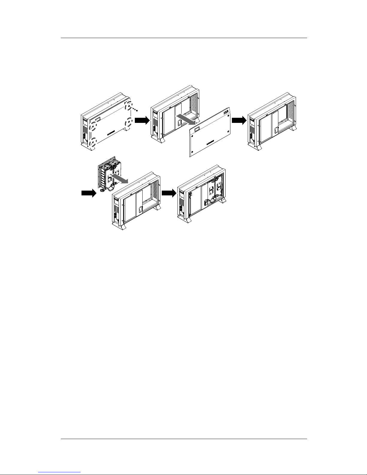
12.Disassembly ......................................................................................................... 92
12.1 Disassembly ............................................................................................................................................ 92
12.1.1 Removing Electric Connection ............................................................................................ 92
12.1.2 Disassembling the Main Body of 3.6 kWh All in One .................................................... 92
12.2 Packaging................................................................................................................................................. 93
12.3 Storage ...................................................................................................................................................... 93
12.4 Disposal .................................................................................................................................................... 93
13.Contact ................................................................................................................. 94
Australia (Eng.) 05/2015. Rev1.1 iii

Table of Tables
Table of Tables
[Table 1-1: Symbol Description] .................................................................................................................... 3
[Table 2-1: Part Description] ........................................................................................................................... 7
[Table 2-2: Basic Specifications] ..................................................................................................................... 8
[Table 3-1: Component Description] ........................................................................................................ 11
[Table 4-1: Weight of All in One] ................................................................................................................ 15
[Table 4-2: Specifications for anchor bolt] .............................................................................................. 17
[Table 5-1: Component Description] ........................................................................................................ 23
[Table 5-2: Part List] ........................................................................................................................................ 25
[Table 5-3: Front Case Open Process] ....................................................................................................... 26
[Table 5-4: Front and Rear view of All in One] ........................................................................................ 27
[Table 5-5: Circuit breaker, DC Disconnection Switch and power line specification] ................ 36
[Table 5-6: RCD Leakage circuit breaker description] .......................................................................... 36
[Table 5-7: Wire Standard] ............................................................................................................................ 38
[Table 6-1: Recommended Meter List] ..................................................................................................... 45
[Table 7-1: Registration Item list] ............................................................................................................... 57
[Table 9-1: Inverter general events warning list] ................................................................................... 70
[Table 9-2: Inverter protection list] ............................................................................................................ 72
[Table 9-3: Battery operation general events list .................................................................................. 73
[Table 9-4: PV general events protection list] ........................................................................................ 74
[Table 9-5: System general events protection list] ............................................................................... 75
[Table 9-6: BMS general events list] .......................................................................................................... 77
[Table 9-7: EMS/communication events list] .......................................................................................... 77
[Table 9-8: Single fault events list] ............................................................................................................. 78
[Table 9-9: Significant events list] .............................................................................................................. 79
[Table 10-1: Replaceable parts list] ............................................................................................................ 86
[Table 11-1: Technical specifications] ....................................................................................................... 89
iv Australia (Eng.) 05/2015. Rev1.1

Table of Figures
Table of Figures
[Figure 2-1: Connection Diagram] ................................................................................................................ 5
[Figure 2-2: Part View of Samsung All in One] .......................................................................................... 7
[Figure 3-1: Process for the enclosure package removal]................................................................... 10
[Figure 3-2: Process for the battery package removal] ....................................................................... 10
[Figure 3-3: Packing List] ............................................................................................................................... 11
[Figure 3-4: Process for the battery assembly] ....................................................................................... 12
[Figure 3-5: Name Plate] ............................................................................................................................... 13
[Figure 4-1: Dimension of All in One] ........................................................................................................ 15
[Figure 4-2: Minimum Clearance for All in One] .................................................................................... 16
[Figure 4-3: Restriction for the surface gradient] .................................................................................. 16
[Figure 4-4: Spanner for fastening anchor nuts] ................................................................................... 17
[Figure 4-5: Anchor Bolt] ............................................................................................................................... 17
[Figure 4-6: A Flat head driver for the front cover knob (larger than 10mm)] ............................. 18
[Figure 4-7: The Plus head driver (No.2) for the tray, the side cover, and grounding] .............. 18
[Figure 4-8: A spanner for fastening use] ................................................................................................ 18
[Figure 4-9: A fork lifter with height of 85-200mm] ............................................................................. 19
[Figure 5-1: Electrical connections] ........................................................................................................... 21
[Figure 5-2: PV connections] ........................................................................................................................ 22
[Figure 5-3: Front Inside View] .................................................................................................................... 24
[Figure 5-4: Rear Inside View] ...................................................................................................................... 24
[Figure 5-5: Side View] ................................................................................................................................... 25
[Figure 5-6: Rear Inside View] ...................................................................................................................... 28
[Figure 5-7: Battery Tray Rear View] .......................................................................................................... 28
[Figure 5-8: Battery Connection] ................................................................................................................ 28
[Figure 5-9: Battery Docking description] ............................................................................................... 29
[Figure 5-10: Battery to BMS Connection] ............................................................................................... 30
[Figure 5-11: Cable Stuff Method].............................................................................................................. 30
[Figure 5-12: Battery Power Connection] ................................................................................................ 31
[Figure 5-13: Front Cover Assembly process 1] ..................................................................................... 32
[Figure 5-14: Front Cover Assembly process 2] ..................................................................................... 33
[Figure 5-15: Front Cover Assembly process 3] ..................................................................................... 33
[Figure 5-16: Front Cover Assembly process 4] ..................................................................................... 34
[Figure 5-17: Distribution box connection diagram] ........................................................................... 35
[Figure 5-18: Electric cable connection for energy meter installation] .......................................... 37
[Figure 5-19: PV connector (Female) and PV line (Male)] ................................................................... 38
[Figure 5-20: Side cover opening] .............................................................................................................. 38
[Figure 5-21: PV connector connection (MC4 connector connection)] ......................................... 39
[Figure 5-22: L and N AC line connection method] .............................................................................. 39
[Figure 5-23: Terminal Block] ....................................................................................................................... 40
[Figure 5-24: Power Cable connection to the terminal block] .......................................................... 40
[Figure 5-25: Side view after side cover assembly] ............................................................................... 41
[Figure 6-1: Internet Connection] .............................................................................................................. 42
[Figure 6-2: Bi-directional D0 Meter Connection] ................................................................................. 43
[Figure 6-3: Bi-directional RS485 Meter Connection (For EM24)] .................................................... 44
[Figure 6-4: RS485 terminal block] ............................................................................................................. 44
[Figure 6-5: Communication terminal] ..................................................................................................... 45
[Figure 6-6: Log-in page] .............................................................................................................................. 46
[Figure 6-7: Password initialization page] ............................................................................................... 47
[Figure 6-8: Monitoring page] ..................................................................................................................... 48
Australia (Eng.) 05/2015. Rev1.1 v

Table of Figures
[Figure 6-9: Consumption report page] ................................................................................................... 48
[Figure 6-10: Forecast page] ........................................................................................................................ 49
[Figure 6-11: Setting page] .......................................................................................................................... 50
[Figure 6-12: Mobile service page] ............................................................................................................ 50
[Figure 7-1: Jumper] ....................................................................................................................................... 52
[Figure 7-2: Initial setup page] .................................................................................................................... 53
[Figure 7-3: Engineer log in page] ............................................................................................................. 55
[Figure 7-4: New ESS add page] ................................................................................................................. 56
[Figure 7-5: ESS status page] ....................................................................................................................... 57
[Figure 7-6: Inverter feed in limit setup page] ....................................................................................... 58
[Figure 7-7: ESS status detail information page] ................................................................................... 58
[Figure 7-8: ESS output setup page] ......................................................................................................... 59
[Figure 7-9: PCS information page] ........................................................................................................... 59
[Figure 8-1: Initial indication screen on power on]............................................................................... 60
[Figure 8-2: Standby state indication screen before the EMS command] ..................................... 60
[Figure 8-3: PV generation, battery charge, Load use, sell remaining amount] .......................... 61
[Figure 8-4: PV generation, battery discharge, Load use, buy shortage amount] ...................... 61
[Figure 8-5: PV generation, Battery standby, Load use, sell remaining amount] ........................ 61
[Figure 8-6: PV generation, Sell remaining amount] ............................................................................ 62
[Figure 8-7: PV generation, Buy shortage amount] .............................................................................. 62
[Figure 8-8: Battery discharge, Load use] ................................................................................................ 62
[Figure 8-9: Battery discharge, Load use, Buy shortage amount] .................................................... 62
[Figure 8-10: Indication screen on Standby Mode] .............................................................................. 63
[Figure 8-11: Indication screen on Forced charged Mode] ................................................................ 63
[Figure 8-12: Indication screen on stand-alone mode] ....................................................................... 63
[Figure 8-13: Event occurrence, Grid RMS over current protection] ............................................... 64
[Figure 8-14: Event occurrence, DC link over voltage protection] ................................................... 64
[Figure 8-15: Event occurrence, PV string1 reverse connection protection] ................................ 64
[Figure 8-16: Event occurrence, PV string2 reverse connection protection] ................................ 64
[Figure 8-17: Event occurrence, PV string1 over voltage protection] ............................................. 65
[Figure 8-18: Event occurrence, PV string1 over current protection] ............................................. 65
[Figure 8-19: Event occurrence, PV string2 over voltage protection] ............................................. 65
[Figure 8-20: Event occurrence, PV string2 over current protection] ............................................. 65
[Figure 8-21: Event occurrence, Battery over voltage protection] .................................................. 65
[Figure 8-22: Event occurrence, Battery over current protection] ................................................... 66
[Figure 8-23: Event occurrence, On sequence Inverter DC link event] ........................................... 66
[Figure 8-24: Event occurrence, On sequence Battery V/I event] .................................................... 66
[Figure 8-25: Event occurrence, Normal Inverter DC link event] ...................................................... 66
[Figure 8-26: Event occurrence, Normal Battery V/I & BDC DC link event].................................... 66
[Figure 8-27: Event occurrence, On sequence Inverter DC link event] ........................................... 67
[Figure 8-28: Event occurrence, Normal Inverter DC link & PV I event] .......................................... 67
[Figure 8-29: Event occurrence, Temperature protection] ................................................................ 67
[Figure 8-30: Event occurrence, Over Current TZ Fault]...................................................................... 67
[Figure 8-31: Events occurrence, temperature sensor connection error] ..................................... 67
[Figure 8-32: Event occurrence, PV mis-wiring] ..................................................................................... 68
[Figure 8-33: Event occurrence, SPI communication event] ............................................................. 68
[Figure 8-34: Event occurrence, Single fault event] ............................................................................. 68
[Figure 8-35: Event occurrence, Continuously 3 times Inverter fault] ............................................ 68
[Figure 8-36: Indication screen on Application Download Mode] .................................................. 68
[Figure 10-1: PV MC4 connector] ............................................................................................................... 80
[Figure 10-2: Side cover removal] .............................................................................................................. 81
[Figure 10-3: Fan removal] ........................................................................................................................... 81
[Figure 10-4: Li-Ion Battery tray (manufactured by SAMSUNG SDI)]............................................... 86
vi Australia (Eng.) 05/2015. Rev1.1

Table of Figures
[Figure 10-5: PV Connector (MC4)] ............................................................................................................ 87
[Figure 11-1: Derating Curve] ...................................................................................................................... 90
[Figure 11-2: Power efficiency curve of System] ................................................................................... 90
[Figure 11-3: Power efficiency curve of PV Generation] ..................................................................... 91
Australia (Eng.) 05/2015. Rev1.1 vii
1. About this Manual
1. About this Manual
1.1 Valid Range
This is the installation manual for the 3.6 kWh All In One system. Please read this installation
and user manual carefully before installing and operating the 3.6 kWh all in one system.
It contains important safety instructions. The warranty will be void if you fail to follow the
instructions in this manual.
1.2 Target Group
This installation manual applies only to the Samsung 3.6 kWh All in One.
1.3 Manual Storage
The user manual and installation manual can be downloaded from the product download
section at
“https://myess.samsungsdi.com”. The specifications of the product can be
changed for improvement without notice.
Also, the software can be updated automatically without notice over the Internet.
1.4 Symbols Used
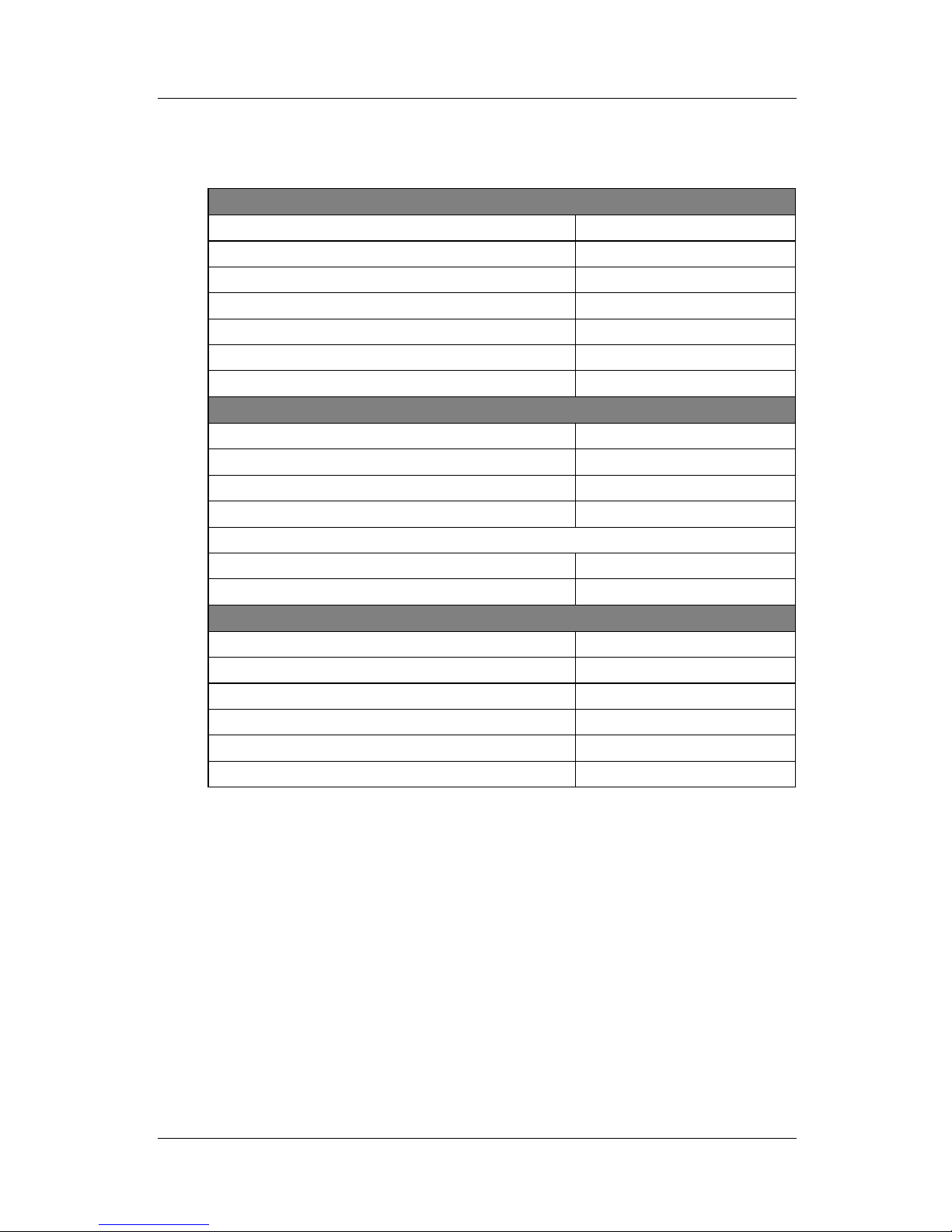
Symbols Meaning
CAUTION
This symbol indicates a hazardous situation which could
result in a light injury, if not avoided.
NOTICE
This symbol indicates a hazardous situation which could
result in damage to the property, if not avoided.
Information
This symbol indicates valuable tips for optimum installation
and operation of the product.
Australia (Eng.) 05/2015. Rev1.1 1
1. About this Manual
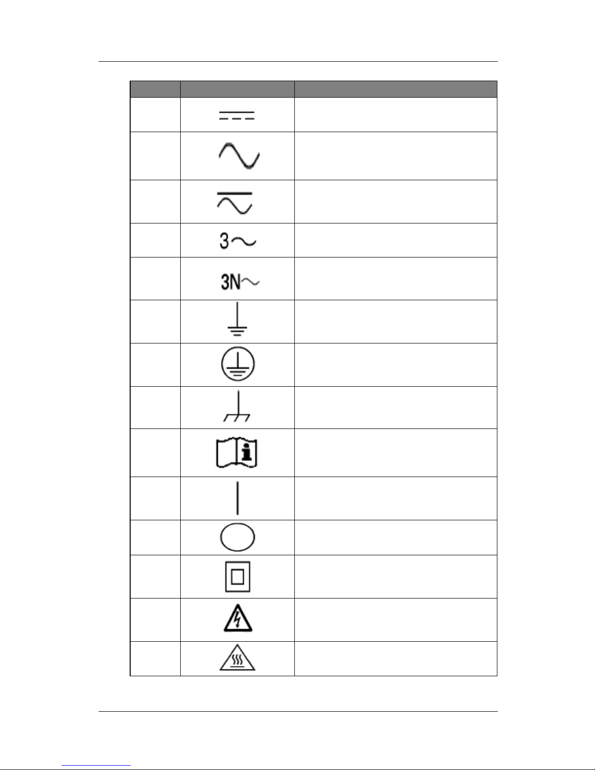
Number Symbol Description
1
Direct current
2
Alternating current
3
Both direct and alternating current
4
Three-phase alternating current
5
Three-phase alternating current with neutral
conductor
6
Earth terminal
7
Protective conductor terminal
8
Frame or chassis terminal
9
Refer to the operating instructions
10
On (supply)
11
Off (supply)
12
Equipment protected throughout by double
insulation or reinforced insulation
13
Caution: Risk of Electric Shock
14
Caution: Hot Surface
2 Australia (Eng.) 05/2015. Rev1.1
1. About this Manual
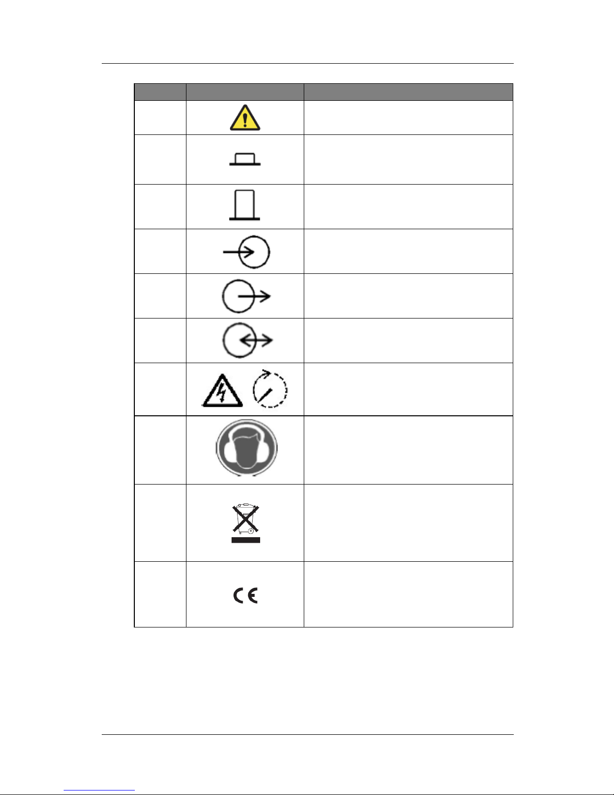
Number Symbol Description
15
Caution: Risk of Danger
16
In position of a bi-stable push control
17
Out position of a bi-stable push control
18
Input terminal or rating
19
Output terminal or rating
20
Bidirectional terminal rating
21
Caution: Risk of Electric Shock and Energy
Storage Timed Discharge
22
Caution: Risk of Hearing Damage and Wear
Hearing Protection Wear hearing protection
23
Do not dispose of the inverter with household
wastes.
For further information on disposal, refer to the
installation manual provided.
24
The CE Indication:
The relevant equipment complies with the
requirements in the EC guidelines.
[Table 1-1: Symbol Description]
Australia (Eng.) 05/2015. Rev1.1 3
2. Safety
2. Safety
2.1 Intended Use
NOTICE
The 3.6 kWh All in One system is intended for residential use only.
The 3.6 kWh All in One system should not be used for commercial or
building.
The 3.6 kWh All in One system is designed for residential use. It is a single-phase, gridconnected system of solar energy sources and Li-on Battery energy storage.
The 3.6 kWh All In One system uses solar energy power connected to the input/output
terminal installed on the side of the device in order to:
1) charge the Li-Ion battery energy storage,
2) provide a supply to the household load, and
3) convert direct current (DC) electricity of the battery to alternating current (AC) to
discharge as household single-phase load or electric system.
This device should not be used for any purpose other than the purpose described in this
installation manual. Any substitute use of this device, random change in any of its parts, and
use of components other than sold or recommended by Samsung SDI will nullify the
product
’s guarantee. For example, Samsung Li-Ion battery energy storage should not be
replaced by other manufacturer’s battery storages. For further information on proper use of
this device, contact the Samsung SDI Service line or visit at “www.samsungsdi.com”.
4 Australia (Eng.) 05/2015. Rev1.1
2. Safety
[Figure 2-1: Connection Diagram]
Australia (Eng.) 05/2015. Rev1.1 5
2. Safety
2.2 Safety Precautions
CAUTION
High voltages in power conditioning circuits. Lethal hazard of electric shock
or serious burns.
All work on the PV modules, inverters, converters, and battery systems must
be carried out by qualified personnel only.
Wear rubber gloves and protective clothing (protective glasses and boots)
when working on high voltage/high current systems such as INVERTER and
battery systems.
CAUTION
Li-Ion battery energy storage system (ESS) inside. When assembling the
system, do not intentionally short the positive (+) and negative (-) terminals
with metallic object.
All work on the ESS and electrical connections must be carried out by
qualified personnel only. The ESS within 3.6 kWh All In One provides a safe
source of electrical energy when operated as intended and as designed.
A potentially hazardous circumstance such as excessive heat or electrolyte
mist may occur due to improper operating conditions, damage, misuse
and/or abuse. The following safety precautions and the warning messages
described in this section must be observed. If any of the following
precautions are not fully understood, or if you have any questions, contact
Customer Support for guidance (see chapter 13).
The safety section may not include all regulations for your locale; personnel
working with 3.6 kWh All In One must review applicable federal, state and
local regulations as well as the industry standards regarding this product.
CAUTION
This product is intended to be used for PV source inputs and residential
home grids (AC 230V). If not used as intended, the protection provided by
the equipment may be impaired.
CAUTION
This device is designed appropriate for two-
PV string structure. Therefore, the
PV string 1 and PV string 2 must be connected to PV input 1 and PV input 2,
respectively.
Do not split one PV string output for connecting it into the PV input terminal
1 and input terminal 2.
6 Australia (Eng.) 05/2015. Rev1.1
2. Safety
2.3 Product Overview
The All In One system includes the PV inverter, battery charger/discharger, Li-Ion battery, and
EMS.
The basic operating modes consist of PV generation mode, PV generation +
charge/discharge mode. The operation mode of this product is automatically determined by
the EMS algorithm.
[Figure 2-2: Part View of Samsung All in One]
No. Description
1 Li-Ion battery
2 INVERTER (PV inverter and battery charger / discharger)
3 Tray BMS
4 Input / Output terminal (MC4-2set and Grid connection terminal -L/N/PE)
5 Cooling Fan
6 Communication
7 Carrying handle
[Table 2-1: Part Description]
Australia (Eng.) 05/2015. Rev1.1 7
2. Safety
2.3.1 Basic Specifications
PV Generator Data (DC)
Max. input total power 6.6 kWp
Max. input power per string 3.3 kWp
Max. input voltage 550 V
Min. input voltage/Initial input voltage 125 V/150 V
MPPT voltage range 125 V~500 V
Max. input current per string 15 A
Number of independent MPP trackers 2
Battery Data (DC)
Battery nominal capacity/usable capacity 3.6 kWh/3.24kWh
DOD(Depth of Discharge)/Range 90% (5~95%)
Battery voltage range/nominal voltage 48.0 V~65.9 V/60 V
Battery Max. current 46.3 A
Battery DC/DC Converter Data
Rated Power 2.0 kW
Technology Isolated
Grid Connection Data (AC)
Rated power 4.6 kW
Max. apparent AC power 5 kVA
Max. current 20 A
Max. allowed current for fuse protection 32 A
Nominal AC voltage/range 230 V/184 V~264 V
Rated power frequency 50 Hz
[Table 2-2: Basic Specifications]
2.3.2 Grounding the PV Inverter
The PV inverter complies with the local requirements for grounding the PV inverter.
Samsung SDI recommends connecting and grounding the PV inverter
’s frame and other
electricity conducting surfaces in such a way that there is continuous conduction in order to
achieve maximum protection for systems and persons. And the PV inverter
’s DC (+) pole
and DC (-) pole are not permitted to be grounded.
8 Australia (Eng.) 05/2015. Rev1.1
3. Package Removal and Inspection
3. Package Removal and Inspection
CAUTION
Included in this box are a battery and printed circuit board, and the entire
weight amounts to 95 kg. Therefore, special care must be taken in handling.
Make sure to have at least two persons deliver and remove the package.
3.1 Package Removal and Tray Assembly
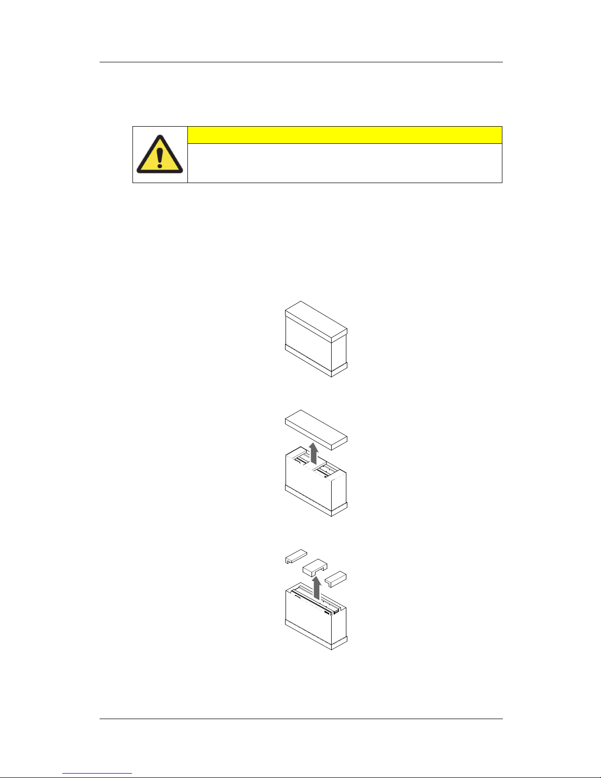
3.1.1 Removing the Enclosure Package
As shown in the figure in this section, remove the package components from the enclosure
in the following order.
1. Place the system on the installation location.
2. Open the upper part of the battery case.
3. Remove both sides of the cover in the front of the product.
Australia (Eng.) 05/2015. Rev1.1 9
3. Package Removal and Inspection
4. Lift the package.
5. Open the side support on the bottom.
[Figure 3-1: Process for the enclosure package removal]
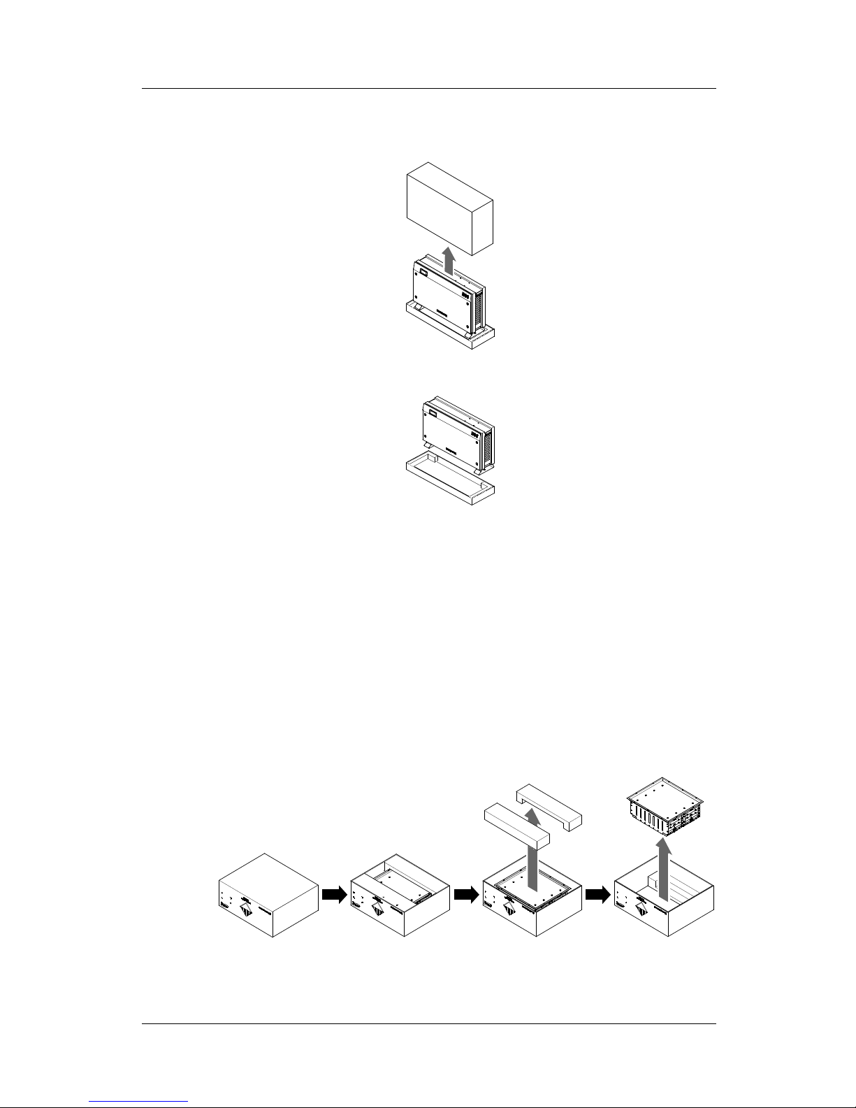
3.1.2 Removing the Battery Tray Package
As shown in the [Figure 3-2], remove the package for the battery tray.
1. Open the box cover of the product.
2. Remove the buffers with a straight pull.
3. Take out the battery tray by grabbing the handle and pulling it up.
Note: The tray weighs approximately 45 kg, so make sure to have at least two persons lift it.
[Figure 3-2: Process for the battery package removal]
10 Australia (Eng.) 05/2015. Rev1.1
3. Package Removal and Inspection
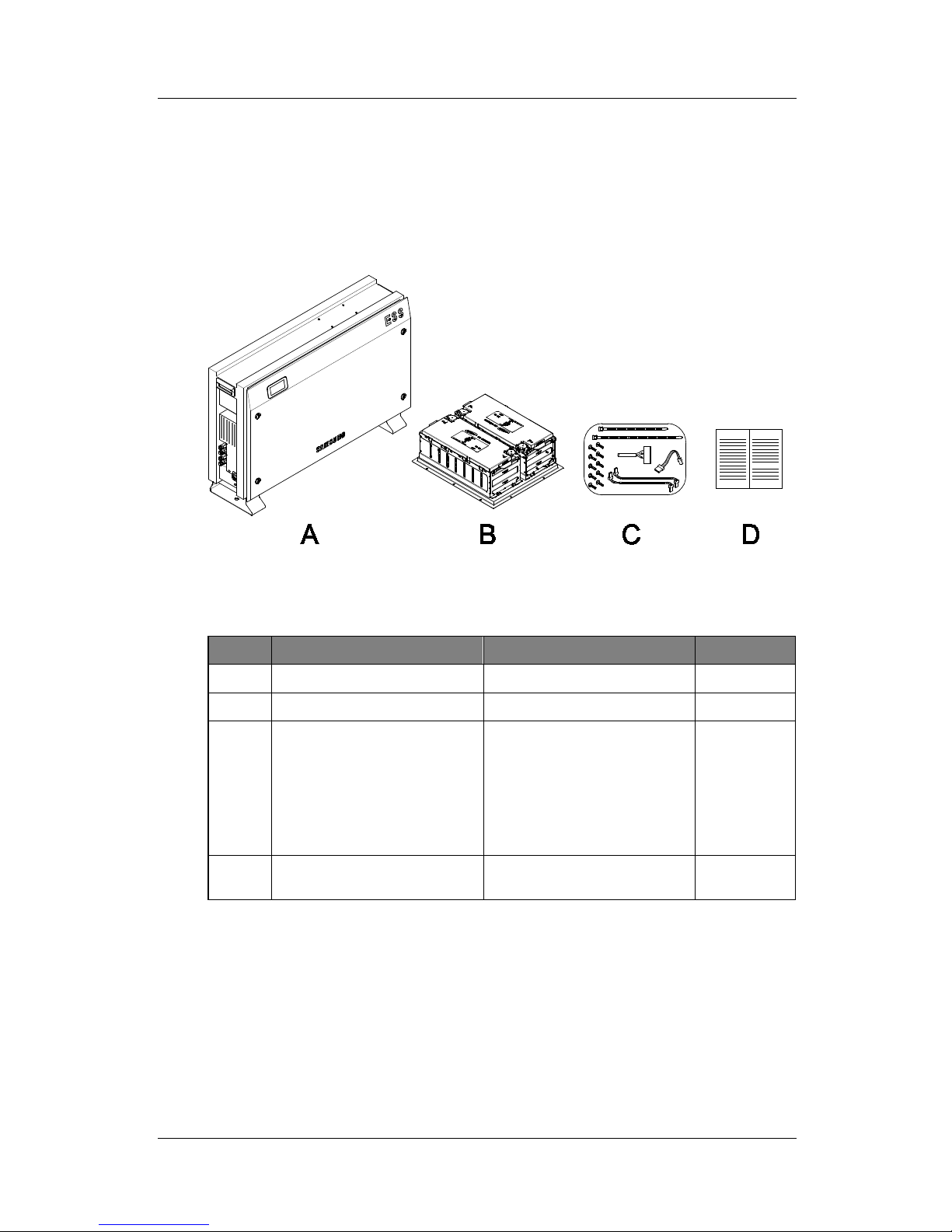
3.1.3 Checking Components on the Packing List
Once the product has been delivered, refer to the figure [Figure 3-3] and [Table 3-1], identify
the entire components included in the package and the correct number of the quantity
listed in the table.
Packing List
[Figure 3-3: Packing List]
Object
Part Name Code No. Quantity
A INVERTER ASSY SJ94-00108D 1
B TRAY ASSY (2nd Module) ELPT362-00002 1
C 1. SCREW(M4xL16)
2. EXTENTION WIRE
3. EXTENTION WIRE (*)
4. EXTENTION WIRE
5. CABLE TIE (A: Long, B: Short)
6. JUMPER WIRE
SJ81-01146
3901-000819
3901-000820
3901-000821
-
3901-000859
10
1
1
1
2
1
D Installation Quick Guide
Manual
SJ68-02069D 1
(*): 3. EXTENTION WIRE may not be needed depending on the type of battery tray
[Table 3-1: Component Description]
Australia (Eng.) 05/2015. Rev1.1 11
3. Package Removal and Inspection
3.1.4 Assembling the Battery Tray
The [Figure 3-4] shows the assembly process for the battery tray. Refer to Clause 5.4 and
assemble the battery tray as described in it.
[Figure 3-4: Process for the battery assembly]
3.2 Checking for damage in Delivery
When opening the box that contains Samsung 3.6 kWh All In One system in it, check for any
possible damage caused in transit and ensure the correct number of the components
therein. If there is a scratch on the enclosure, contact your local dealer for inspection and
service.
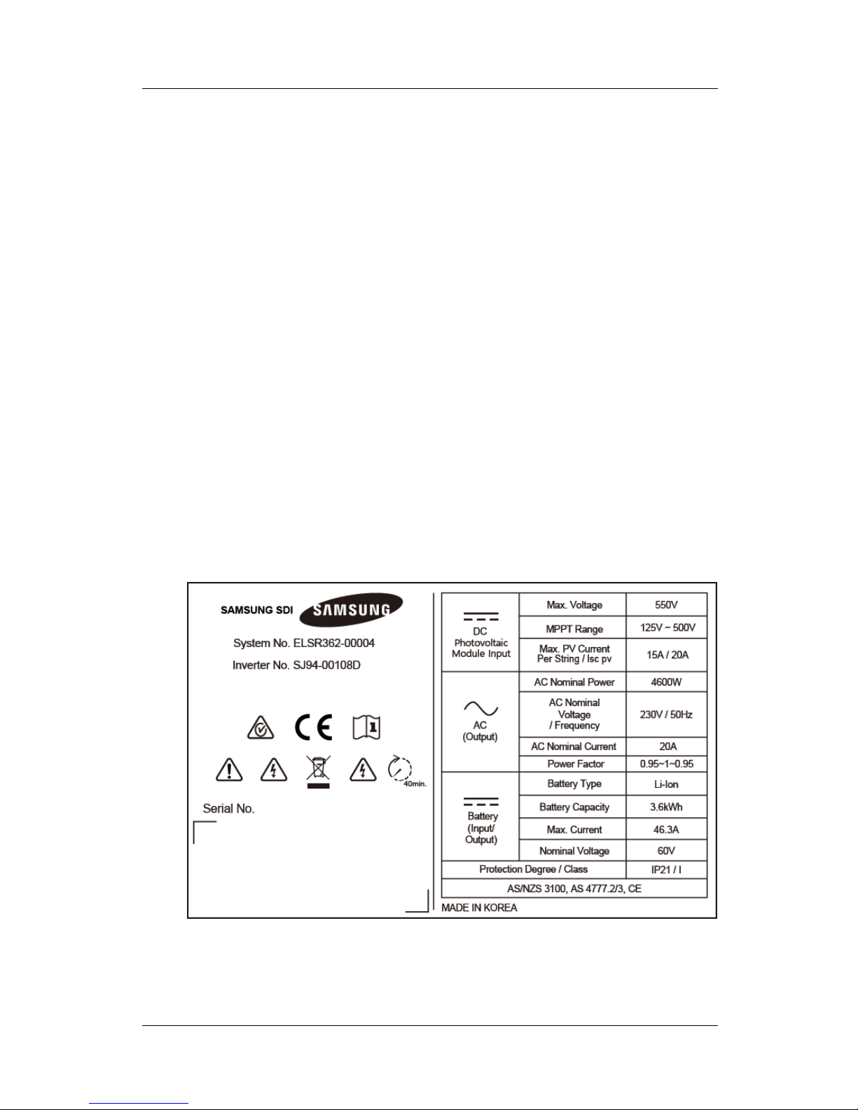
3.3 Identifying Samsung 3.6 kWh All in One
Attached on the enclosure of this product is the Type Label where the identity of this
product is described. For safe usage, make sure that the following product information is
indicated on the Type Label.
■ Product Name
■ Device Type (Model)
■ Serial Number (Serial No.)
■ Device-specific characteristics
■ Certification Lists
12 Australia (Eng.) 05/2015. Rev1.1
3. Package Removal and Inspection
■ Warnings and Notification
The model No. of 3.6 kWh All In One system is defined as below.
■ ELSR362-00004
• ELSR: Residential application
• 36: Battery capacity (x0.1kWh)
• 2: Battery capacity group (Less than 10kW)
• 00004: product line number
The model No. of INVERTER (power conditioning system) is defined as below.
■ SJ94-00108D
• SJ: battery for ESS
• 94: Ass’y
• 00108: product number
• D: National Code (Australia)
The Type Label is shown in the [Figure 3-5].
[Figure 3-5: Name Plate]
Australia (Eng.) 05/2015. Rev1.1 13
4. Installation
4. Installation
4.1 Selection of Installation Location
CAUTION
Danger to life due to fire or explosion!
Danger to life due to high voltages!
Despite careful construction, a fire can occur with electrical devices.
Do not install the 3.6 kWh All In One on the following locations:
On flammable construction materials;
In potentially explosive areas; and
In areas where highly flammable materials are stored!
CAUTION
Li-Ion battery energy storage is equipped within 3.6 kWh All in One.
The ESS within 3.6 kWh All In One provides a safe source of electrical
energy when operated as intended and as designed.
A potentially hazardous circumstance such as excessive heat or
electrolyte mist may occur due to improper operating conditions,
damage, misuse and/or abuse. The following safety precautions and
the warning messages described in this section must be observed.
If any of the following precautions are not fully understood, or if you
have any questions, contact Customer Support for guidance. The
Safety Section may not include all regulations for your locale;
Personnel working with 3.6 kWh All In One must review applicable
federal, state and local regulations as well as the industry standards
regarding this product.
CAUTION
All work on the ESS and electrical connections must be carried out by
qualified personnel only.
14 Australia (Eng.) 05/2015. Rev1.1
4. Installation
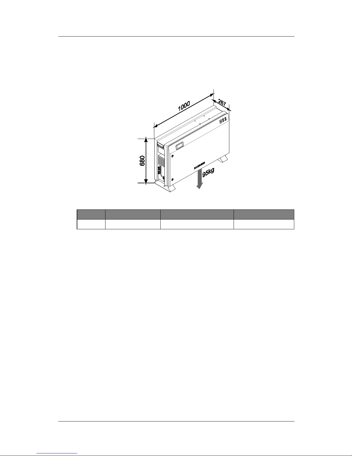
4.1.1 Dimensions and Weight
Once the 3.6 kWh All In One system has been assembled, its dimension is 1000 x 680 x
267mm, and its weight is approximately 95kg. The [Figure 4-1] and [Table 4-1] show the
outer dimensions and the weight of the device after assembly, respectively.
[Figure 4-1: Dimension of All in One]
Battery Inverter ( Include case) Total
Weight 45kg 50kg 95kg
[Table 4-1: Weight of All in One]
4.1.2 Ambient Conditions and Temperatures
Identify a proper installation location to install and remove the device easily at any time.
This device must be located within reach distance.
The ambient temperature of the installation location will range from -10°C to +40°C.
4.1.3 Minimum Clearance
This device is required to maintain a minimum clearance distance for the safe installation of
the product. Refer to the [Figure 4-2] to secure enough space and keep a distance of 0.1m
from the wall, 1m in the front of the device, 1m and 0.3m on each side, and 0.3m on top.
Australia (Eng.) 05/2015. Rev1.1 15
4. Installation
[Figure 4-2: Minimum Clearance for All in One]
4.1.4 Position (Location Selection)
As shown in the [Figure 4-3], install the device on a flat surface. (Front, back, left, right
gradient within ±0.5°)
To allow for natural ventilation, the side of the system must be kept away from the wall
about 0.3m at least. Make sure not to have foreign substances and objects stuck in the
blowing fan, ventilation entrance and exit sides.
[Figure 4-3: Restriction for the surface gradient]
16 Australia (Eng.) 05/2015. Rev1.1
4. Installation
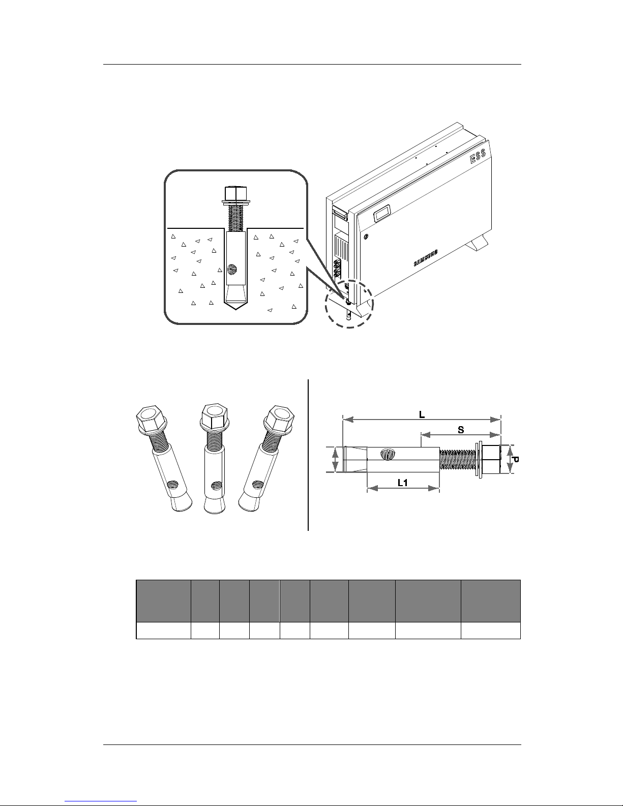
4.2 Mounting Instructions
[Figure 4-4: Spanner for fastening anchor nuts]
[Figure 4-5: Anchor Bolt]
Screw
name
L S D L1
Drill
Used
Drill
depth
(Min.)
Tensile
capacity
(Max.)
Shear
Capacity
(Max.)
1/2 (M12) 100 60 17 50 17 55 (mm) 3,200 (kgf ) 3,400 (kgf )
[Table 4-2: Specifications for anchor bolt]
Australia (Eng.) 05/2015. Rev1.1 17
4. Installation
1. Select the drill proper for specifications for drilling specifications.
2. Remove the dust from the hole, then separate the nut and the washer to insert both the
bolt and the cap.
3. Set the product in place, assemble the washer and the nut to the bolt, and then use the
spanner to fasten the nut (7N∙m).
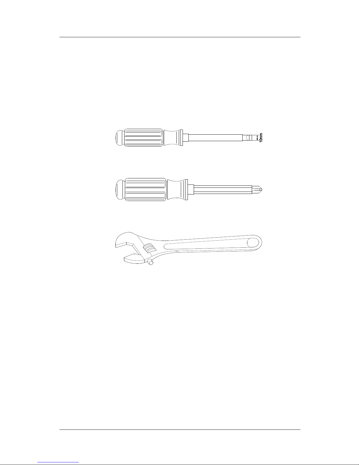
Required tools for installation
[Figure 4-6: A Flat head driver for the front cover knob (larger than 10mm)]
[Figure 4-7: The Plus head driver (No.2) for the tray, the side cover, and grounding]
[Figure 4-8: A spanner for fastening use]
18 Australia (Eng.) 05/2015. Rev1.1
4. Installation
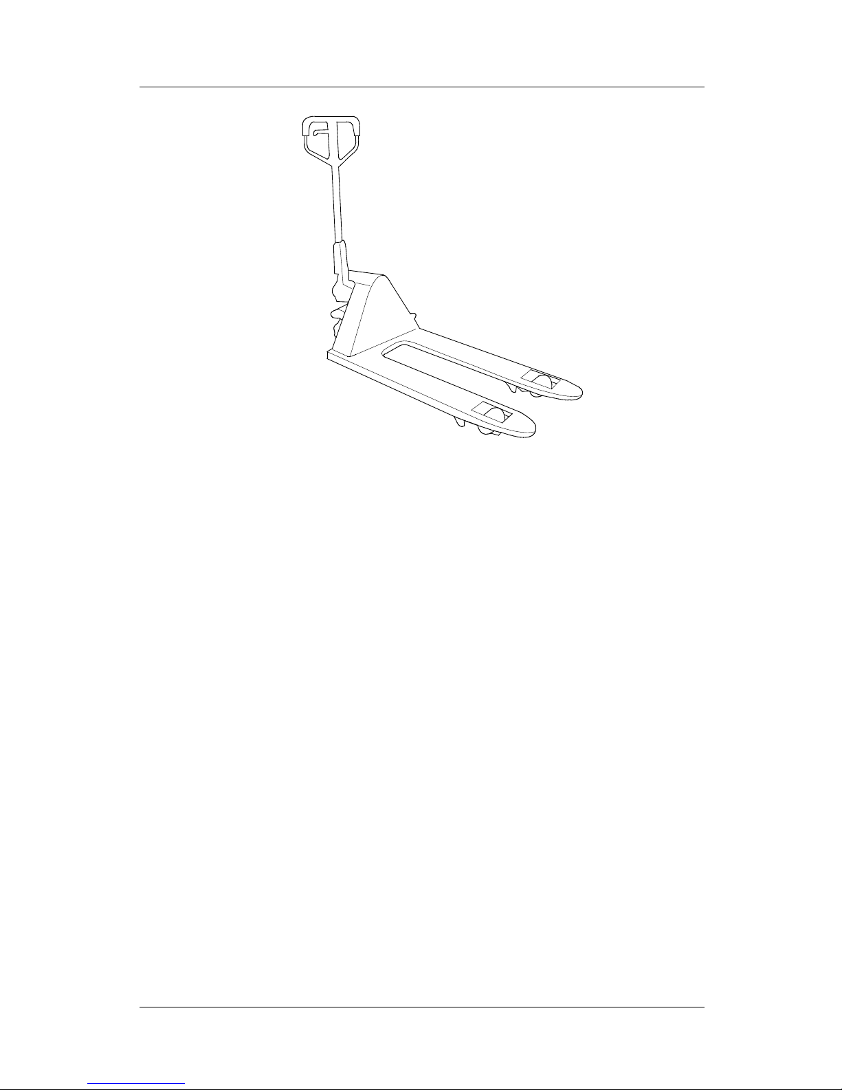
[Figure 4-9: A fork lifter with height of 85-200mm]
Australia (Eng.) 05/2015. Rev1.1 19
5. Electrical Connections
5. Electrical Connections
NOTICE
The 3.6 kWh All In One system can be damaged by static discharge.
Before you touch a component inside the 3.6 kWh All in One, ground
yourself by touching PE or a grounded object
CAUTION
When handling with the Li-Ion Battery Tray for the 3.6 kWh All in One, you
must wear the following personal protective equipment:
High voltage rated rubber gloves
Safety goggles or other protective eye equipment
40-minute standby period of time to complete discharging in the system
before testing electrical parts inside the system!
Follow the guidelines below when handling the Li-Ion Battery Tray.
Do not intentionally short circuit the positive (+) and negative (-) terminals
with a metallic object.
Do not remove the cap on the terminals. If the cap is removed, avoid
contact between the metals and the battery terminals. Do not damage the
screw thread.
Do not use seriously scarred or deformed battery. Dispose immediately
according to proper regulations.
Do not damage sheath of cable and connectors.
20 Australia (Eng.) 05/2015. Rev1.1
5. Electrical Connections
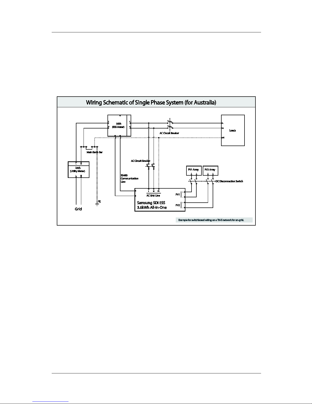
5.1 The Overview of Electrical Connection
The 3.6 kWh All In One has two solar energy inputs (PV1, PV2). 3.3 kW (per string) is the
maximum output for each PV input. The AC output of All in One is connected to the Home
Load and the Grid. Between the Home Load and the Grid, the Digital Energy Meter is placed
for power metering. The AC circuit breaker and DC Disconnect switch in the distribution box
are installed between the All in One for safety reasons.
[Figure 5-1: Electrical connections]
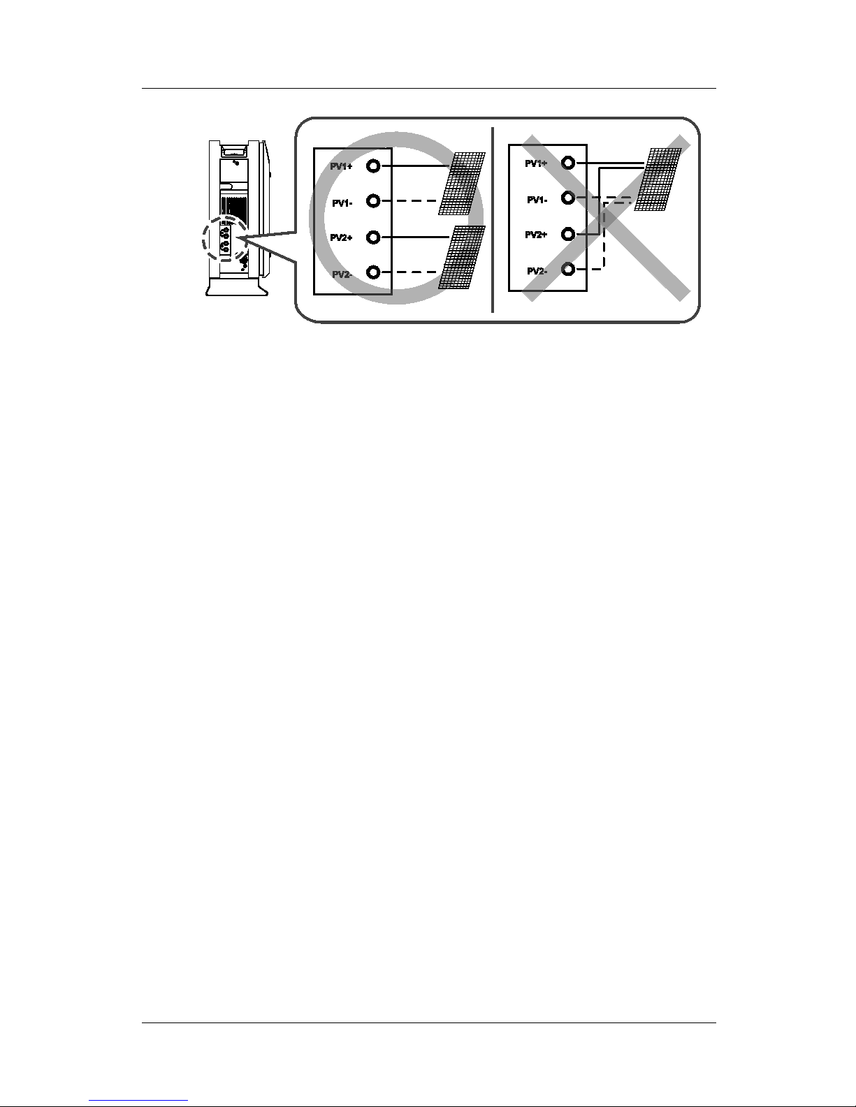
As shown in the [Figure 5-2][Figure 5-2: PV connections], the 3.6 kWh All In One uses the two
independent channels of the PV Input ({PV1+, PV1-}, {PV2+, PV2-}). They are used
independently for running the maximum power from the sources of PV1 and PV2. Two
channels are recommended for independent use for the two PV Inputs. Make sure not to
connect one PV string in parallel with the two independent PV inputs (PV1, PV2). (Refer to
3.6 kWh All In One Solar energy input connection in the [Figure 5-2]).
A PV string must not be commonly connected to the two input terminals of the All in One
system. That is, make sure not to connect the split wiring from one PV string output with the
two independent PV inputs (PV1+, PV1- and PV2+, PV2-). (Refer to the PV String connection
method in the [Figure 5-2]).
※ PV modules shall have an IEC61730 Application Class A rating or equivalent.
Australia (Eng.) 05/2015. Rev1.1 21
5. Electrical Connections
[Figure 5-2: PV connections]
22 Australia (Eng.) 05/2015. Rev1.1
 Loading...