

Samsung EH052EAMC, EH070EAMC, DH094EAMC Installation Manual
E S F I P D G R
DB98-27157A(1)
INSTALLATION
MANUAL
System Air Conditioner
ENGLISH
ESPAÑOLFRANÇAISITALIANOPORTUGUÊSDEUTSCH
EΛΛHNIKA
RUSSIAN
EH052EAMC
EH070EAMC
DH094EAMC
DB98-27157A(1)_E.indd 37 2007-1-23 10:36:06
E-2
Safety Precautions
The following safety precautions must be taken when using your air conditioner.
WARNING
The unit should not be installed by the user. Ask the dealer or authorized-
company to install the units except room air conditioners for the U.S.A and
Canada area.
If the unit is installed improperly, water leakage, electric shock or fire may
result.
Mount with the lowest moving parts at least 2.5 m above the floor or grade
level. (If applicable)
The manufacturer does not assume responsibility for accidents or injury-
caused by an incorrectly installed air conditioner. If you are unsure aboutin
-
stallation, contact an installation specialist.
When installing the built-in type air conditioner, keep all electrical cablessuch
as the power cable and the connection cord in pipe, ducts, cablechannels e.t.c
to protect them against liquids, outside impacts and so on.
This appliance is not accessible to the general public. This applianceshould
be installed according to the provided installation instruction.
INSTALLING THE UNIT
If the power cord of this air conditioner is damaged, it must be replaced
bythe manufacturer, its service agent or similarly qualified persons in order
toavoid a hazard.
The unit must be plugged into an independent circuit if applicable or con-
nect the power cable to the auxiliary circuit breaker. An all pole disconnec
tion from the power supply must be incorporated in the fixedwiring with a
contact opening of >3mm.
Do not use an extension cord with this product.
If the unit is equipped with a power supply cord and a plug, the plug must-
be accessible after installation.
The air conditioner must be installed in accordance with national wiring
regulations and safety regulations wherever applicable.
POWER SUPPLY
LINE,FUSE OR
CIRCUIT BREAKER
• Risk of electric shock Can cause injury or death. • Disconnect all remote electric
power supplies before servicing, installing or cleaning.
•
This must be done by the
manufacturer or its service agent or a similarqualified person in order to avoid a
hazard.
DB98-27157A(1)_E.indd 2 2007-1-23 13:06:29
E-3
ENGLISH
ESPAÑOLITALIANOITALIANOPORTUGUÊSDEUTSCH
EΛΛHNIKA
RUSSIAN
Preparation for Installation............................................................................ 4
Deciding on Where to Install the Air Conditioner ....................................... 5
Indoor Unit Installation ................................................................................ 9
Purging the Unit .......................................................................................... 10
Connecting the Connection Cord ................................................................ 11
Drain Hose Installation ................................................................................ 13
Connecting the Indoor Unit Assembly Piping .............................................. 15
Cutting/Flaring the Pipes ............................................................................. 16
Checking Correct Grounding ....................................................................... 17
Performing Leak Tests ................................................................................ 18
Insulation ..................................................................................................... 19
Adjusting Air Flow ....................................................................................... 20
Setting Up the Mode Option ........................................................................ 21
Assigning Address to Indoor Unit ................................................................ 24
Additional Functions .................................................................................... 25
Drain Pump Installation (Optional) ............................................................... 27
Troubleshooting .......................................................................................... 29
Parts List ................................................................................................... 33
Contents
DB98-27157A(1)_E.indd 3 2007-1-23 13:06:29
E-4
Preparation for Installation
When deciding on the location of the air conditioner with the owner,
the following restrictions must be taken into account.
Do NOT install the air conditioner in a location where it will come into
contact with the following elements:
Combustible gases
Saline air
Machine oil
Sulphide gas
Special environmental conditions
If you must install the unit in such conditions, first consult your dealer.
Cable-Tie Cable Clamp
M4 x 16 Tapped
Screws
Indoor unit power draw-
ing cable
Communication cable
ofthe wired remote con
-
troller
Wire joint
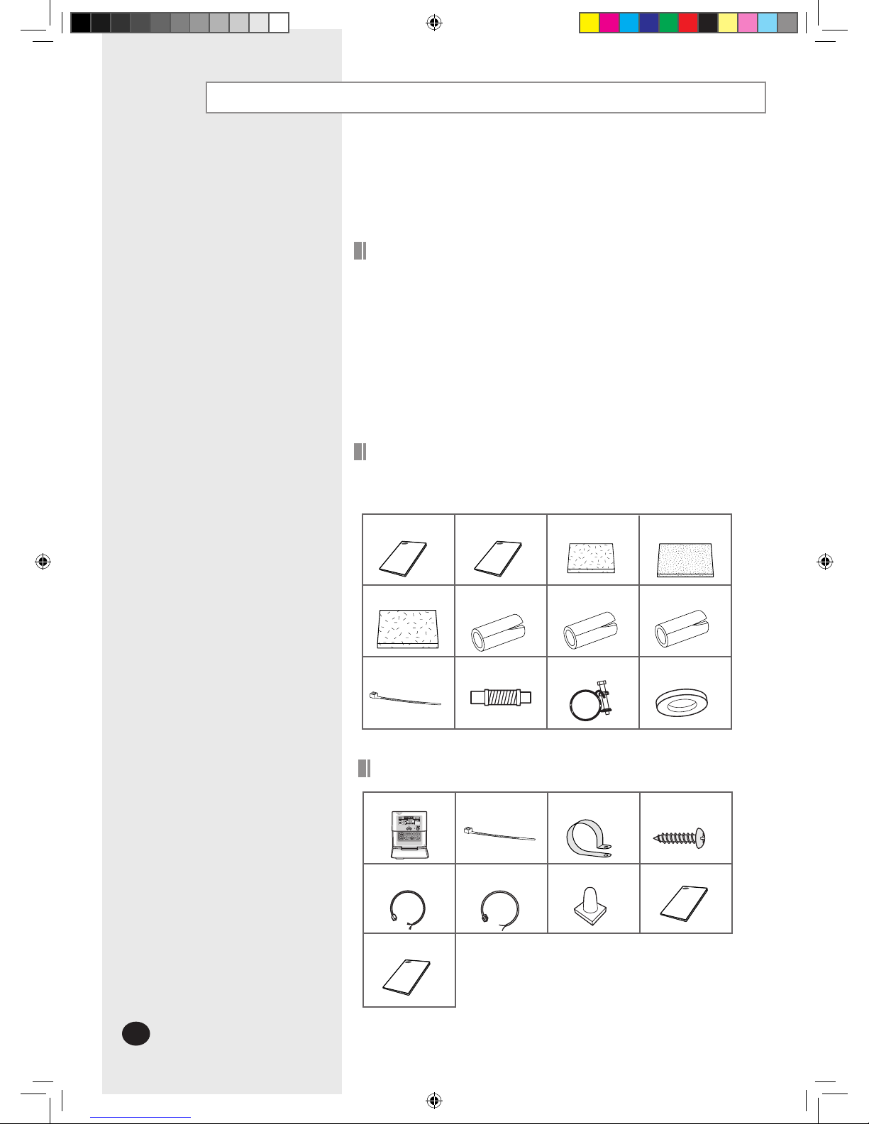
Owner’s Instruction
Installation Manual
Wired remote controller
Accessories
General
Wired Remote Controller Accessories
The following accessories are supplied with the indoor unit.
The type and quantity may differ depending on the specifications.
Installation
Manual(1)
Owner’sInstruc-
tions(1)
Insulation Cover
Pipe in(1)
Insulation
Cover Pipe out(1)
Insulation Pipe in(1)
Insulation
CoverDrain(1)
Insulation Pipe out(1)
Clamp hose(2)
Cable-Tie(8)
Flexible hose(1)
Insulation Drain (1)
Rubber(8)
DB98-27157A(1)_E.indd 4 2007-1-23 13:06:31
E-5
ENGLISH
ESPAÑOLITALIANOITALIANOPORTUGUÊSDEUTSCH
EΛΛHNIKA
RUSSIAN
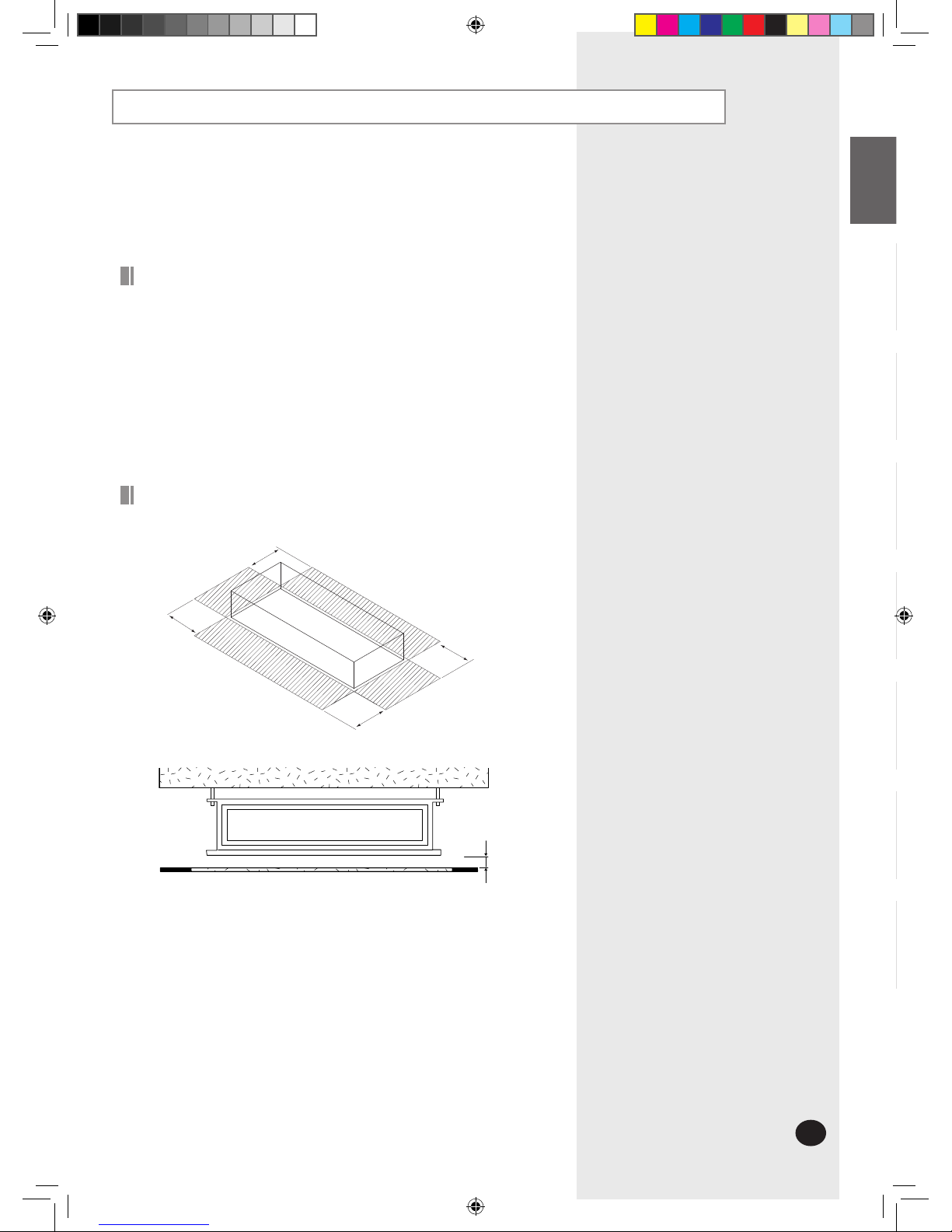
Deciding on Where to Install the Air Conditioner
5mm
Indoor Unit
There must be no obstacles near the air inlet and outlet.
Install the indoor unit on a ceiling that can support its weight.
Maintain sufficient clearance around the indoor unit.
Make sure that the water dripping from the drain hose runs away cor
-
rectlyand safely.
The indoor unit must be installed in this way, that they are out of publi
-
caccess. (Not touchable by the users)
After connecting a chamber, insulate the connection part between the
indoorunit and the chamber with t10 or thicker insulation. Otherwise,
there can beair leak or dew from the connection part.
Space Requirements for Indoor Unit
1500mm or more
1500mm or more
1500mm or more
1500mm or more
DB98-27157A(1)_E.indd 5 2007-1-23 13:06:32
E-6
938.4
1000
8 100=800
86
0
7
74
0
0
6
8
2
82
900
22-ø3.2
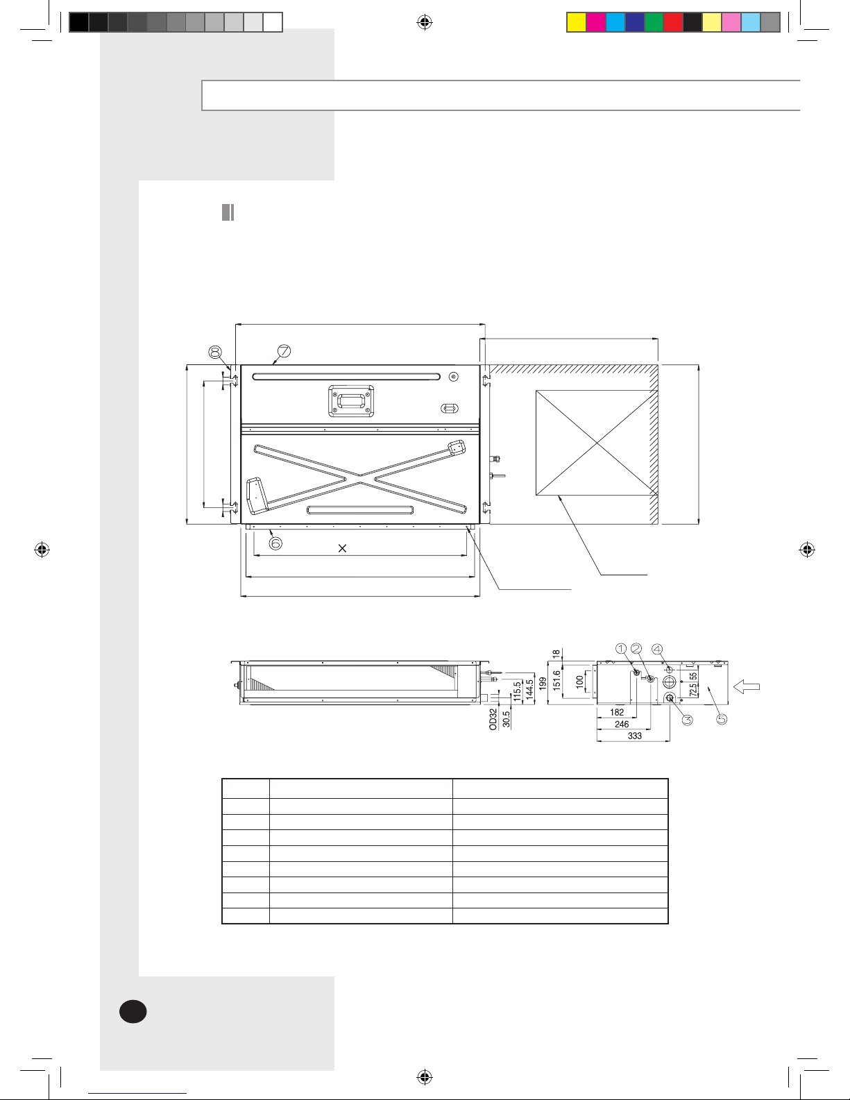
Deciding on where to install the Air Conditioner (Continued)
Unit : mm
Drawing of the indoor unit
Number
Name
Description
1
Liquid pipe connection Ø6,35 Flare
2
RGas pipe connection Ø12,7 Flare
3
Drain pipe connection
OD32 ID26
4
Drain pipe connection
Using drain pump (Optional)
5
Power supply connection
6
Air discharge flange
7
Air filter
8 Hook
For M8~M10
(Suspension position)
(Suspension position)
(Air outlet duct flange)
or more
Inspection hole
Discharge side
EH052EAMC
(Service place)
Suction side
(
Air outlet duct flange
)
DB98-27157A(1)_E.indd 6 2007-1-23 13:06:33
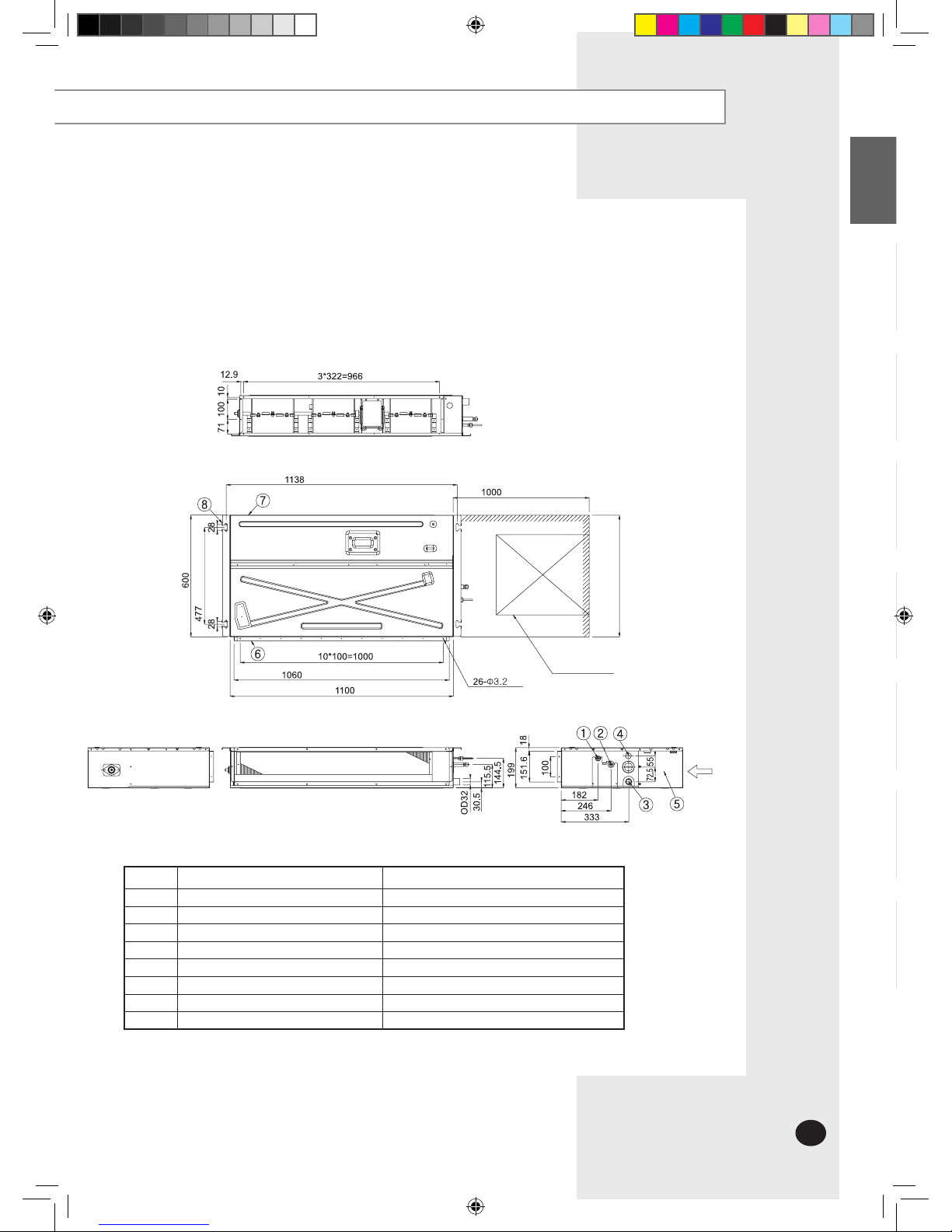
E-7
ENGLISH
ESPAÑOLITALIANOITALIANOPORTUGUÊSDEUTSCH
EΛΛHNIKA
RUSSIAN
(Suspension position)
(Suspension position)
Inspection hole
or more
(
Air outlet duct flange
r)
Unit : mm
EH070EAMC
(
Air outlet duct flange
)
(Service place)
Number
Name
Description
1
Liquid pipe connection Ø9,52 Flare
2
RGas pipe connection Ø15,88 Flare
3
Drain pipe connection
OD32 ID26
4
Drain pipe connection
Using drain pump (Optional)
5
Power supply connection
6
Air discharge flange
7
Air filter
8 Hook
For M8~M10
Discharge side
Suction side
DB98-27157A(1)_E.indd 7 2007-1-23 13:09:01
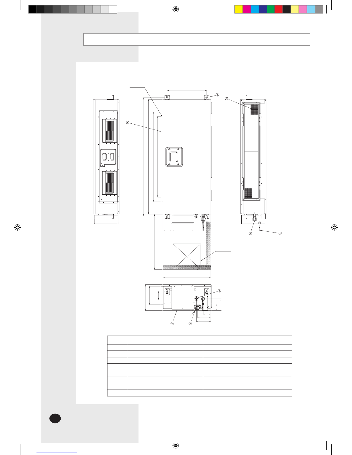
E-8
397
18-Ø3.2
1188
6X135=810
1150
904
1000
260
117
67
185
90
90
220
480
76
132
144
ODØ32
Unit : mm
DH094EAMC
(Suspension position)
(
Air outlet duct flange
r)
(
Suspension position
)
or more
Deciding on where to install the Air Conditioner (Continued)
Number
Name
Description
1
Liquid pipe connection Ø9,52 Flare
2
RGas pipe connection Ø15,88 Flare
3
Drain pipe connection
OD32 ID26
4
Drain pipe connection
Using drain pump (Optional)
5
Power supply connection
6
Air discharge flange
7
Air filter
8 Hook
For M8~M10
Inspection hole
(Service place)
(
Air outlet duct flange
r)
Discharge side
Suction side
DB98-27157A(1)_E.indd 8 2007-1-23 13:06:35
E-9
ENGLISH
ESPAÑOLITALIANOITALIANOPORTUGUÊSDEUTSCH
EΛΛHNIKA
RUSSIAN
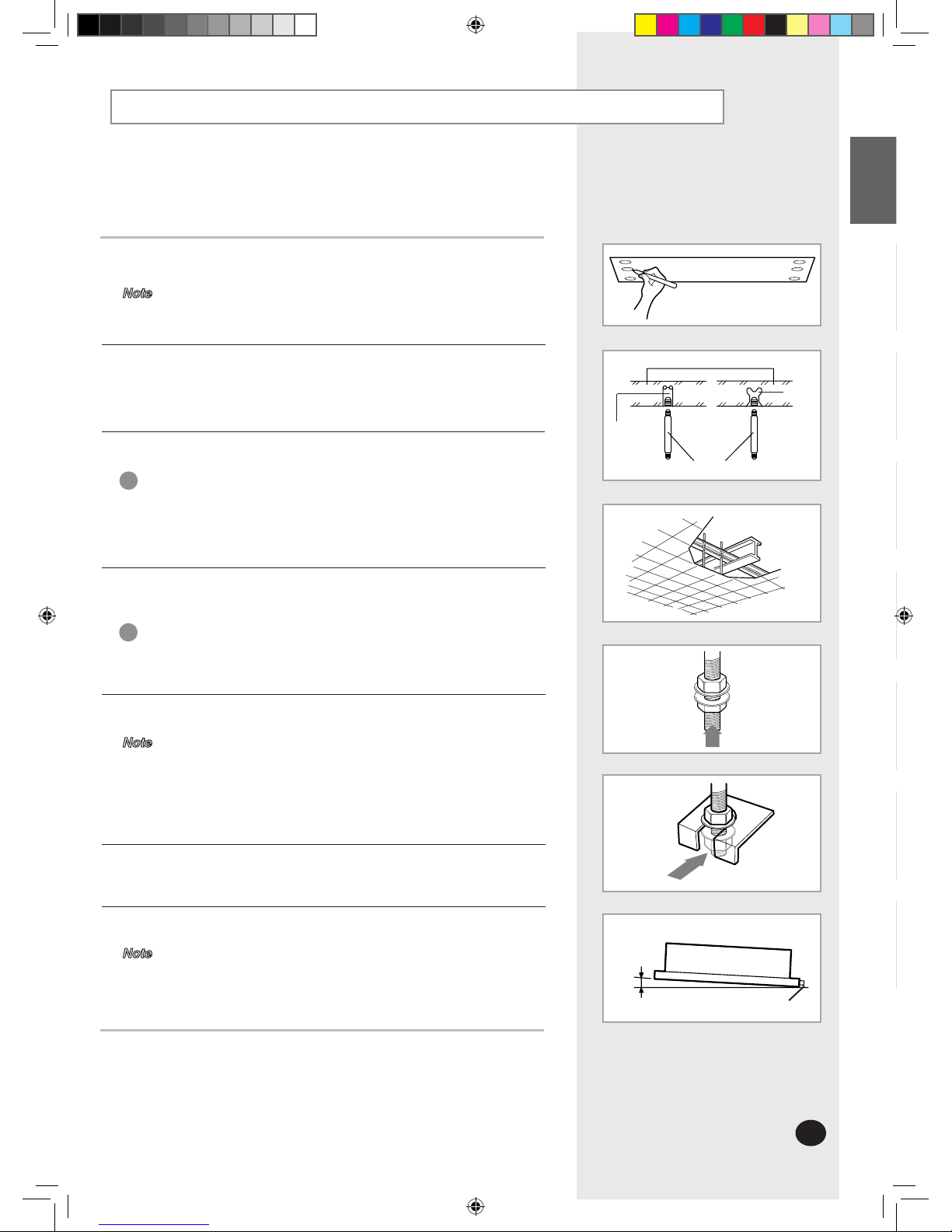
Indoor Unit Installation
1
Mark the place to insert the suspension bolt where you want to install
theindoor unit.
2
Insert bolt anchors. Use existing ceiling supports or construct a suitablesupport as shown in figure.
5
Hang the indoor unit to the suspension bolts between two nuts.
6
Screw the nuts to suspend the unit.
7
Adjust level of the unit by using measurement plate for all 4 sides.
3
Install the suspension bolts depending on the ceiling type.
Ensure that the ceiling is strong enough to support the
weight of the indoor unit.Before hanging the unit, test
the strength of eachattached suspension bolt.
IMPORTANT
4
Screw eight nuts to the suspension bolts making space for hanging the
indoor unit.
You must install the suspension bolts more than 4
when installing the indoor unit.
IMPORTANT
Tubing must be laid and connected inside the ceiling when
suspending the unit. If the ceiling is already constructed, lay
the tubing into position for connection to the unit before plac
-
ing the unit inside the ceiling.
Note
Refer to page 6~8 for the dimension.
Note
For proper drainage of condensate, give a 10mm slant to
the left or right side of the unit which will be connected with
the drainhose, as shown in the figure. Make a tilt when you
wish to install the drain pump, too.
Note
Support du plafond
Drain hose connection port
10mm
Concrete
Suspension bolt(M8)-field supply
Hole in anchor
Hole in plug
Insert
DB98-27157A(1)_E.indd 9 2007-1-23 13:06:36
E-10
Purging the Unit
On delivery, the indoor unit is loaded with an inert nitrogen gas. All
this gas must therefore be purged before connecting the assem
-
blypiping. To purge the inert gas, proceed as follows.
Unscrew the caps at the end of each pipe.
Result:All inert gas escapes from the indoor unit.
To prevent dirt or foreign objects from getting into the pipes
during installation, do NOTremove the caps completely unti
lyou are ready to connect the piping.
Note
DB98-27157A(1)_E.indd 10 2007-1-23 13:06:37
E-11
ENGLISH
ESPAÑOLITALIANOITALIANOPORTUGUÊSDEUTSCH
EΛΛHNIKA
RUSSIAN
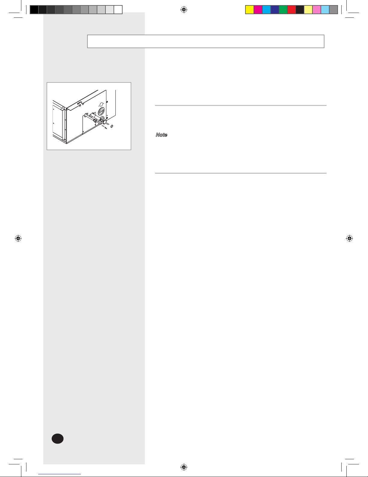
Connecting the Connection Cord
The indoor unit is powered from the outdoor unit via the connection
cord.
When connecting the cables, you must pass them through
the cable clamp to fix them securely.
Connect the Connection Cord as seen in next picture ,
and the torque of screw is 40~70kgf•cm .
Note
Remove the screw on the electrical component box and remove the cover
plate.
1
Route the connection cord through the side of the indoor unit and connectthe cable to terminals as shown in page 12.
2
Route the other end of the cable to the outdoor unit through the ceiling &the
hole on the wall.
3
Reassemble the electrical component box cover, carefully tightening thescrew.
4
DB98-27157A(1)_E.indd 11 2007-1-23 13:06:37
 Loading...