

Samsung DX-408, DX-408i Installation Manual


Class A
This product is registered as one complying with transmission of electromagnetic waves
suitable for business use. Sellers or users should notice this fact and be careful in using this
unit. If you improperly purchase this product, Samsung recommends that you exchange it for
another product for domestic use.
i
Notice
No part of this manual may be used or reproduced without permission from Samsung
Electronics Co., Ltd.
The specifications and appearance of this product may be changed for quality improvement
without prior notice. Accordingly, all information contained in this manual is also subject to
change without notice.

ii
Manual Organization
This manual is an installer’s guide containing information on system specification, how to
install and set up the DX-408/DX-408i digital key system and how to connect additional
equipment.
The DX-408 and DX-408i digital key systems provide the same number of stations
(4 keysets and 4 SLT’s). The DX-408 digital key system accommodates 4
analogue trunk lines, DX-408i digital key system accommodates 2 BRI lines (4
channels). This manual uses notes such as (DX-408) or (DX-408i) when
explaining the different features of each system. Where not noted the explanation
refers to a common feature of both systems.
The chapters of this manual include the following contents.
Chapter 1 “DX-408/DX-408i Digital Key System Overview”, describes the features of the DX408/DX-408i digital key system, appearance and internal structure of the system, and
precautions related to system installation.
Chapter 2 “DX-408/DX-408i Digital Key System Installation”, provides general installation
information for the DX-408/DX-408i digital key system.
Chapter 3 “Additional Equipment Connection”, describes various equipment that can be
additionally installed on the DX-408/DX-408i digital key system.
Appendix A “System Specifications”, describes the DX-408/DX-408i digital key system
specifications for power, environment, and lines.
Appendix B “Mounting Template”, provides the mounting template necessary to hang the DX408/DX-408i digital key system on the wall.

Table of Contents
iii
Chapter 1
System Features .............................................................................................................. 1-1
System Overview.............................................................................................................. 1-2
System Details .................................................................................................................. 1-2
System Specifications ....................................................................................................... 1-2
System Structure ............................................................................................................... 1-3
Product Safety Precautions ............................................................................................. 1-6
DX-408/DX- 408i Di git al Key Syst em Overview
1-1~1-6
Chapter 2 DX-408/D X-408 i Di gital Key System Inst al lation 2-1~2-28
Installation Environment ................................................................................................... 2-1
Installation Precautions .................................................................................................... 2-2
Selecting Place .................................................................................................................. 2-2
Preventing Static Electricity ............................................................................................. 2-2
Correct Cable Requirements ............................................................................................. 2-2
Conditions of Line ............................................................................................................ 2-3
Checking Power ................................................................................................................ 2-3
Installing System .............................................................................................................. 2-4
Prior to Installation ........................................................................................................... 2-4
Installing System .............................................................................................................. 2-5
Checking System Options .............................................................................................. 2-22
Memory Backup Selection ............................................................................................. 2-22
Music Source Selection ................................................................................................. 2-22
Replacing ROMs ............................................................................................................ 2-23
Testing Initial System Operation .................................................................................... 2-25
Connecting Power Supply to System .............................................................................. 2-25
Trunk Line and Station Line Basically Assigned ............................................................ 2-26
Description of Keyset Buttons ........................................................................................ 2-27
Chapter 3 Connection of Additional Equipment .......... 3-1~3-12
Connecting Additional Equipment .................................................................................... 3-1
Music-on-Hold/Background Music .................................................................................. 3-1
External Paging ................................................................................................................. 3-3
Common Bell .................................................................................................................... 3-4
Station Message Detail Recording (SMDR) ..................................................................... 3-5
PC and Remote Programming .......................................................................................... 3-6
CTM-CTI Module ............................................................................................................ 3-8
Voice Mail/Automatic Attendant ...................................................................................... 3-9
Door -Phone and Door Lock Release ............................................................................. 3-10

iv
Appendix A System Specifications ....................... A-1~A-2
Power Specifications ........................................................................................................ A-1
Environment Specifications ............................................................................................. A-1
Line Specifications .......................................................................................................... A-1
Others ............................................................................................................................... A-2
Appendix B Mounting Template............................. B-1~B-1


Chapter
1
DX-408/DX-408i
Digital Key System
Overview
The DX-408/DX-408i digital key system is designed for the small office/ho me office. Both
DX-408/DX-408i digital Key systems utilise a baseboard to provide 8 station circuits (4
circuits for digital keysets and 4 circuits for analogue telephones (SLT’s)) and 4 trunk circuits.
The DX-408 digital key system accommodates 4 analogue trunk lines and the DX-408i digital
key system accommodates 2 BRI lines (4 Channels). In addition, one of the BRI ports (2
Channels) of the DX-408i system can be substituted for ISDN extensions.
System Features
The
!
DX-408 and DX-408I are both digital key systems offering a simple and compact
design.
The
!
DX-408 and DX-408i systems support Plug & Play functionality and are easy to install.
The
!
DX-408 and DX-408i systems support a Door Phone Interface Module (DPIM)
connection allowing connection of a door-phone.
Both
!
!
DX-408 and DX-408i digital key systems accommodate 8 station circuits.
The
DX-408 digital key system accommodates 4 analogue trunk lines. The DX-408i digital
key system can provide 4 digital trunk channels using both ISDN interfaces. However, the
second BRI port can be configured as a Network Termination (NT) rather than 2 digital
trunks. That is, it becomes an extension port to provide access to ISDN terminal equipment
attached to the DX408I as extension equipment. A typical application would be to connect
a router to this port – this could be used to dial out to the ISDN network via the DX408i.
The DX-408/DX-408i digital key systems do not support AOMs or keyset
daughter boards.
2
System Overview
System Details
System items Details
CPU MC68EC000 (16MHz) 16Bit Mode
Memory
Switch Structure 256 x 256 Time Slot
SIO port RS-232C (SIO)
System Specifi cations
ROM (DX-408) : 1Mbytes (2 x 27C4001)
ROM (DX-408i) :
RAM : 256 Kbytes (2x681000)
2Mbyte (4 x 27C4001)
Items Height (mm) Width (mm) Depth (mm) Mass (Kg)
DX-408/DX-408i 190 350 60 2.0
DPIM 29 90 120 0.2
System Structure
System Capacity
DX-408 : 4 analogue trunk lines
Trunk
Station
Music-on-hold/ Background music
channel
General-purpose dry contact 1
SIO port 1
External Page 1
The 8 station ports have a fixed configuration - 4 digital keysets and 4 analogue
telephones.
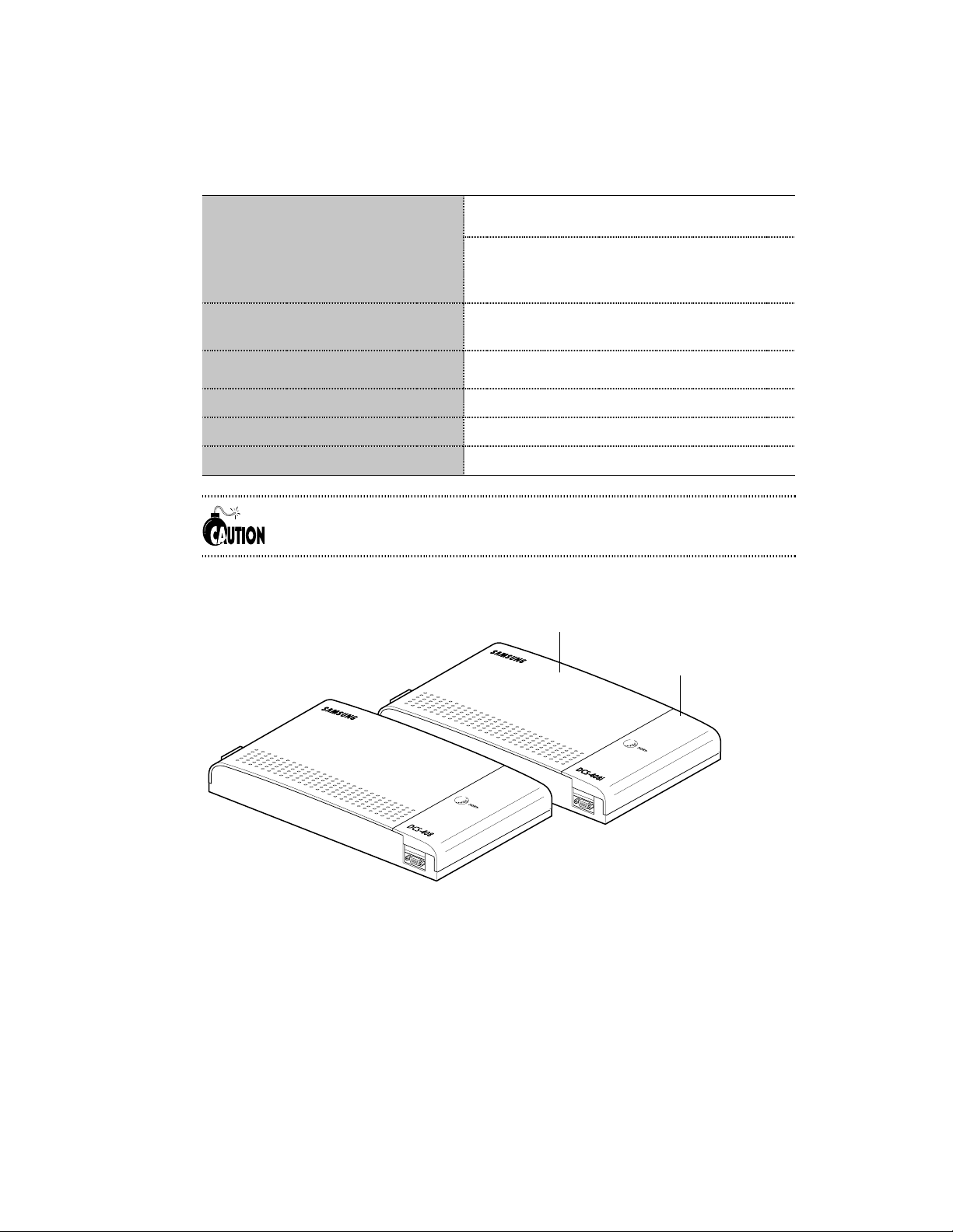
Front View of System
DX-408i : 2 BRI lines (4 Channels)
(CO3.4/BRI2 line (2 Channels) can be substituted
for ISDN extensions)
8 circuits (4 circuits for digital keysets and 4
circuits for analogue telephones)
1 (internal or external)
Front cover
Side cover
DX-408
DX-408i
4
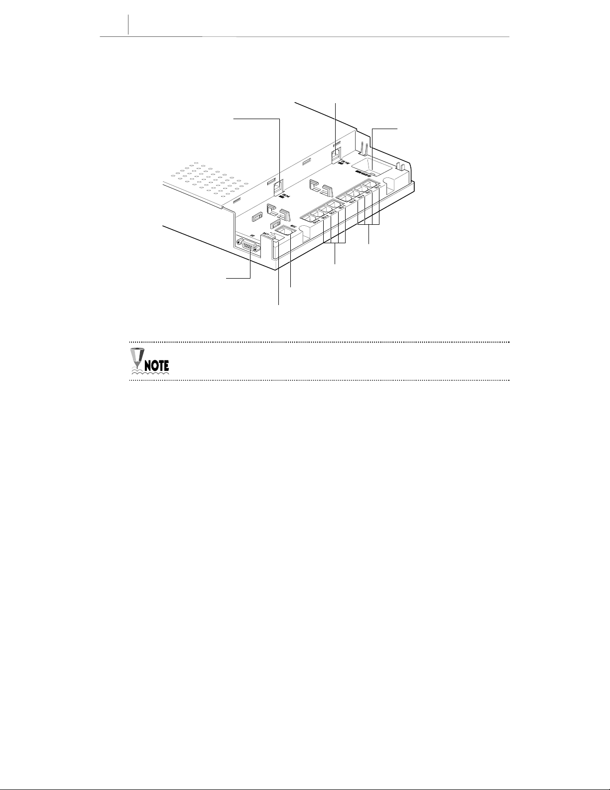
System Ports (After Removing Side Cover)
CO1.2/BRI1 port
CO3.4/BRI2 port
Memory backup switch
SLI ports (Single line interface ports:25-28)
SIO port (For RS-232C)
The PSTN or [BRI1, BRI2] port locations are clearly identified on the equipment.
DLI ports (Digital line interface ports:21-24)
MISC port (general-purpose dry contact/
external music source port/
Battery port
External Page port)
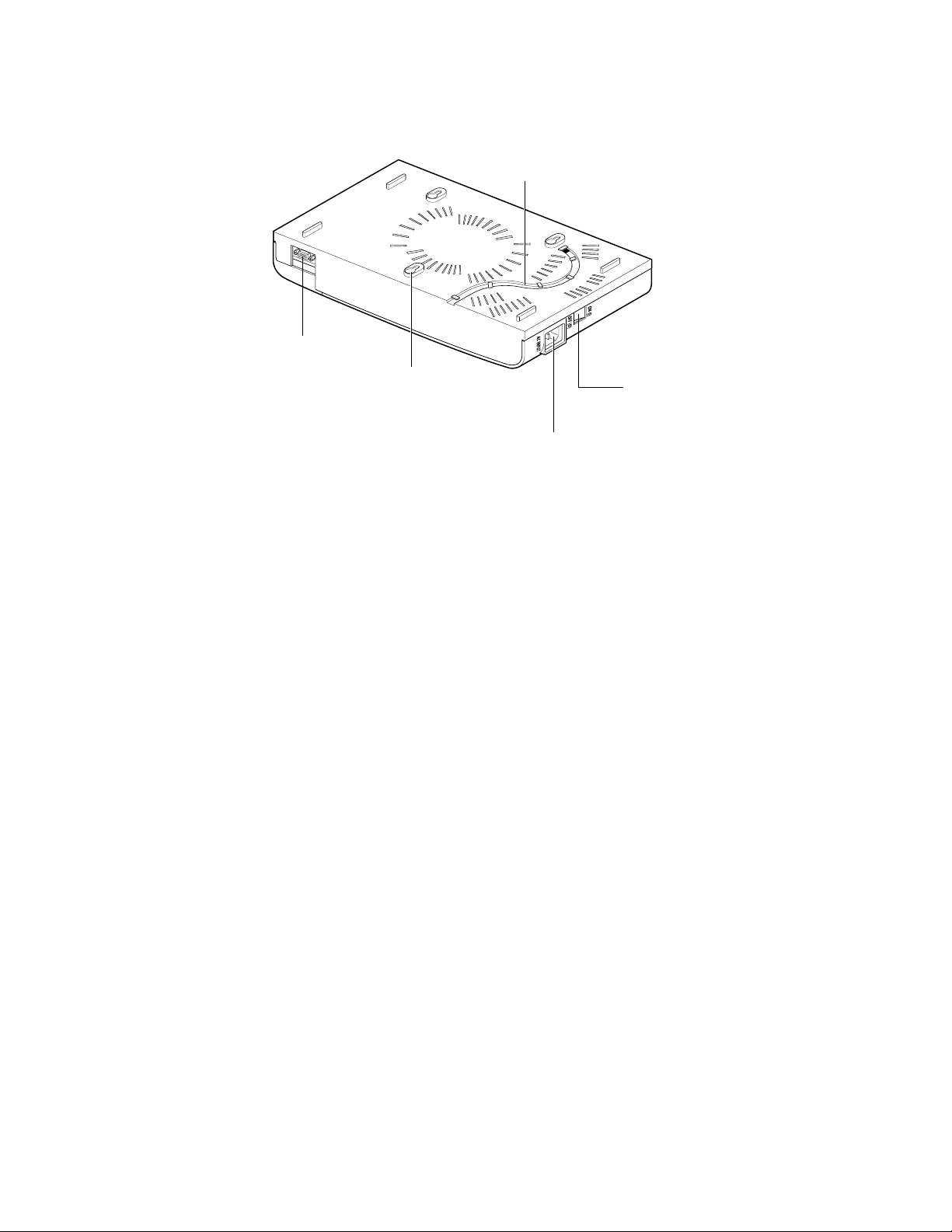
Bottom View of the system
SIO port (for RS-232C)
Groove for ground connection cable requirements.
Not Required in Australia
Groove used for hanging the system on a wall
Power connector
Power switch

6
Site Requirements
The installation site for the Samsung DX 408 systems should meet the following requirements –
The locati on for the key servi ce unit (KSU) must provide enough spac e for easy i nstallation and
have adequate lighting and ventilation.
Select a location that will minimize cable lengths. Observe the maximum cable length limits
indicated in this manual
.
The equipment should not be exposed to moisture, direct sunlight, corrosive fumes, dust, constant
vibration or strong magnetic fields such as those generated by motors and copy machines.
A single phase, c o rrec t ly ea rthed, 240V, 10Amp, 50Hz, AC General Purpose Outlet (GPO) must
be provided wi thin two metres of the KSU. The GPO must be easily accessible and kept clear of
obstructions. Extension cords must not be used. A dedicated, separately fused circuit should be
used to mini mize the risk of other electrical equipment being connected that could adversely affect
system oper ati on.
The equip m e nt m us t be l oc ated in an en vir o n m e nt th at will re main within t h e Temperature ra nge of
0oC to 45oC and 10% to 95% Relative Humidity, non-condensing.
Allow at leas t 3 0c m c learance on b ot h s i des a n d 3 0cm cleara nce on top of the K S U to ensure
proper ve nt il ati o n.
Do not inst all th e K S U i n cl os e proximit y to a f ir e s pri nk l er h ead or ot h er sources of w at er.
Immunity to Interference.
The DX 408 Systems have been designed to be
immune to the levels of interference normally
found within residential and commercial
premises (for example, mains dips and breaks,
electro-static discharge, overvoltages and
transients, electromagnetic fields).

2-1
Chapter
2
DX-408/DX-408i Digital
Key System Installation
Installation Precautions
Selecting Location
Select a location providing sufficient space and good light to facilitate installation and
servicing of the DX-408/DX-408i digital key system.
Minimising Static Electricity
Antistatic precautions should be observed during installation and maintenance on the system.
The DX-408/DX-408I systems must be plugged into a properly earthed mains supply socket.
Correct Cable Re q uirements
Select a KSU location minimizing the length of the system cable, and ensure that all the lines
or cables from and to the DX-408/DX-408i digital key system are protected from damage. In
addition, be careful to minimise interference from electromagnetic waves by avoiding the
running of cables parallel to an AC power cable.
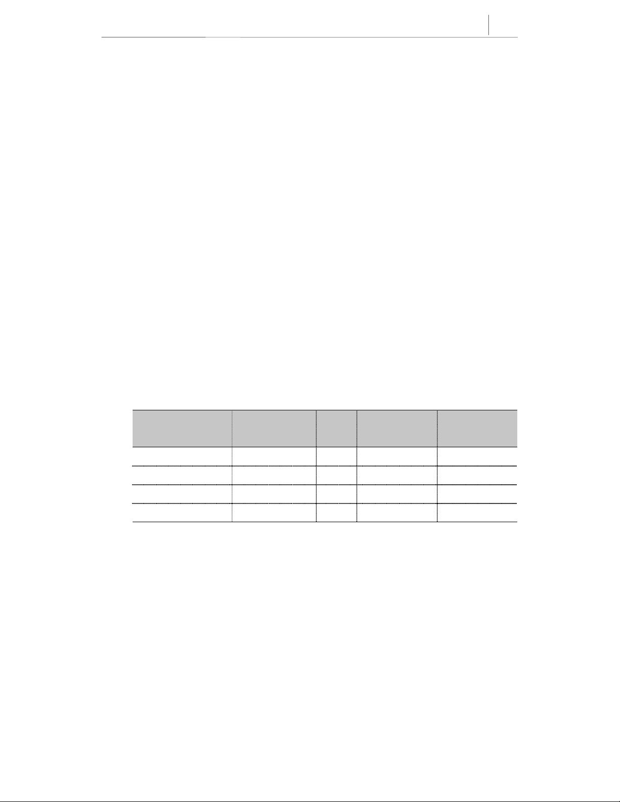
Refer to the cable requirements shown in the following table.
Wire
Equipment Cables
Digital keyset 1PR. Twisted .50 1300 400
Analogue telephone 1PR. Twisted .50 3000 1000
Door phone 2PR. Twisted .50 330 100
DPIM 1PR. Twisted .50 1000 300
Dia
(mm)
MAX FEET(ft) MAX METRE(m)
2-2
Chapter 2
DX-408/DX-408i Digital Key System Installation
Line Conditions
When using .50mm conductor cable, the maximum length of a line for an analogue telephone
is 1000m, and the maximum length of a line for a digital keyset is 400m.
Checking Power
In order to reduce operational problems with the DX-408/DX-408i systems due to mains
voltage drop and possible interruption of power, it is recommended that a separately fused
GPO be used.
Connect the DX-408/DX-408I digital key system to a dedicated GPO in order to
minimise noise problems or system malfunction due to mains voltage drops.
 Loading...