

Samsung DW80M9960US/AC, DW80M9960US/AA, DW80M9960UG/AC, DW80M9550US/AC, DW80M9990US/AA Service Manual
...
DISHWASHER
Model Name : DW80M9*** Series
Model Code :
SERVICE
DW80M9960US/AA
DW80M9550US/AA
DW80M9960UG/AA
DW80M9550UG/AA
DW80M9960US/AC
DW80M9960UG/AC
DW80M9550US/AC
DW80M9990US/AA
DW80M9990UM/AA
Manual
DISHWASHER CONTENTS
1. Safety Instructions
2. Features and Specications
3. Disassembly and Reassembly
4. Troubleshooting
5. PCB Diagram
6. Wiring Diagram
7. Reference

CONTENTS
1. Safety Instructions ...................................................................1
1-1. Safety Instructions for Service Engineers .............................................1
2. Features and Specications ...........................................................5
2-1. Features ....................................................................... 5
2-2. Specications
2-3. ComparingSpecicationswithExistingModels ......................................... 7
2-4. OptionsSpecications ............................................................8
................................................................... 6
3. Disassembly and Reassembly
3-1. ToolsforRemovalandReassembly ..................................................9
3-2. Preparationforpartsreplacement ..................................................10
3-3. RemovingTheUpperRack .......................................................10
3-4. CheckpointsafterFinishingService ................................................. 33
4. Troubleshooting ....................................................................34
4-1. Preparation ....................................................................34
4-2. ServiceInspectionMode .........................................................39
4-3. Checkcodetroubleshooting ......................................................45
5. PCB Diagram ......................................................................54
5-1. MainPCB ..................................................................... 54
5-2. PCBDiagram .................................................................55
6. Wiring Diagram ..................................................................... 56
6-1. WIRINGDIAGRAM ............................................................56
7. Reference .........................................................................58
7-1. ModelNumberNamingRules .....................................................58
7-2. Terminology ..................................................................59
.......................................................... 9
1. SAFETY INSTRUCTIONS
1-1. SAFETY INSTRUCTIONS FOR SERVICE ENGINEERS
ሪ Make sure to observe the following instructions to operate the product correctly and safely and prevent possible
accidents and hazards while servicing.
ሪ Two types of safety symbols, Warning and Caution, are used in the safety instructions.
Warning
Caution
Hazards or unsafe practices that may result in severe personal injury or death.
Hazards or unsafe practices that may result in minor personal injury or property damage.
Warning
Before Servicing
ࣃ (When servicing electrical parts or harnesses) Make sure to disconnect the circuit breaker or power cable before
servicing.
- Failure to do so may result in a risk of electric shock.
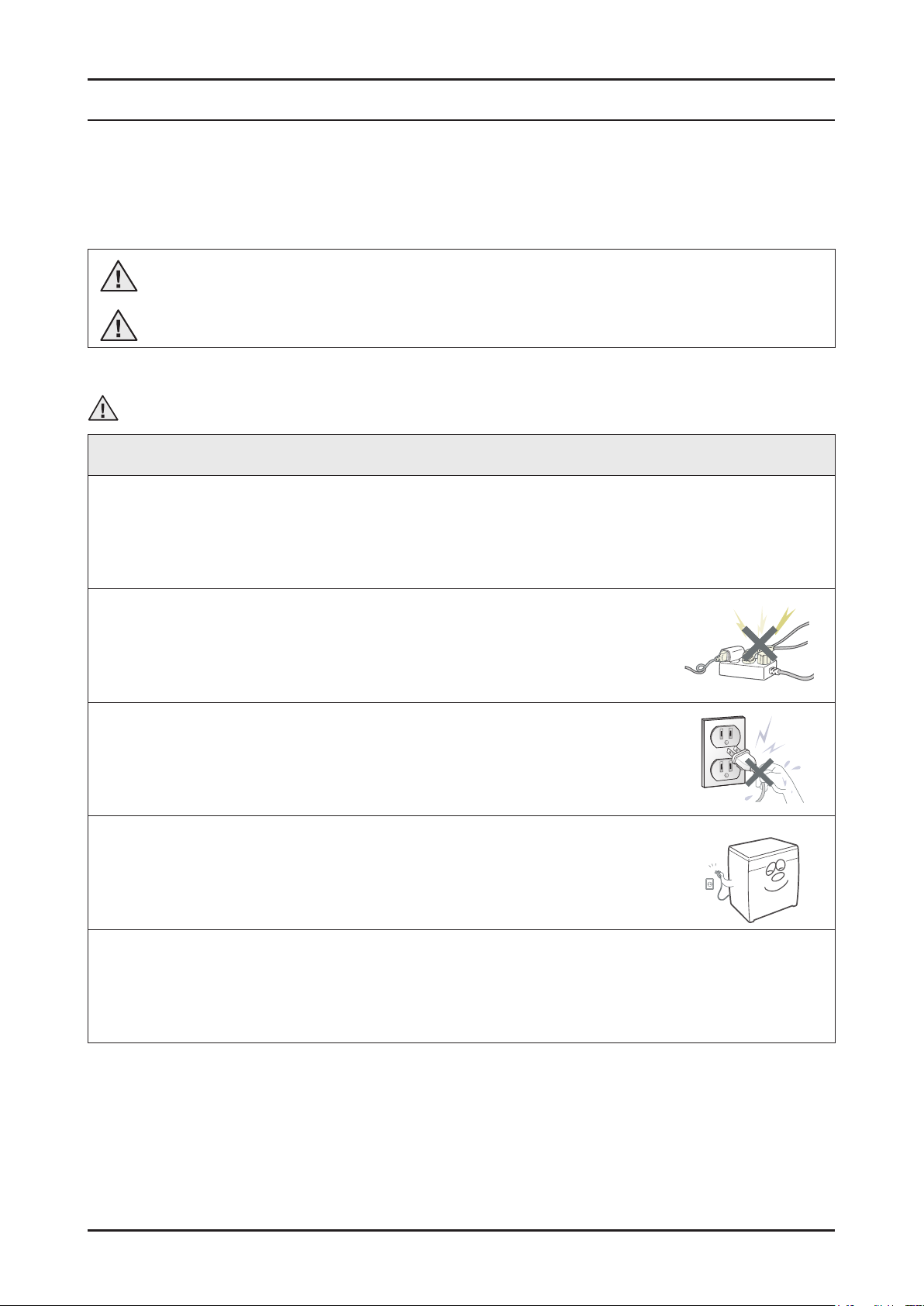
ࣃ Do not allow consumers to connect several appliances to a single power outlet at the
same time.
- There is a risk of re due to overheating.
ࣃ When removing the power cord, make sure to hold the power plug when pulling the plug
from the outlet.
- Failure to do so may damage the plug and result in re or electric shock.
ࣃ When the dishwasher is not being used, make sure to disconnect the circuit breaker or
power cable from the power outlet.
- Failure to do so may result in electric shock or re due to lightning.
ࣃ Do not place or use gasoline, thinners, alcohol, or other ammable or explosive substances near the dishwasher.
- There is a risk of explosion and re caused from electric sparks.
Safety Instructions _ 1
While Servicing
ࣃ Check if the power cable is damaged, attened, cut or otherwise degraded.
- If faulty, replace it immediately. Failure to do so may result in electric shock or re.
ࣃ Completely remove any dust or foreign material from the housing, wiring and connection parts.
- This will prevent a risk of re due to arcing and short circuits in advance.
ࣃ When connecting wires, make sure to connect them using the correct connectors and check that they are
completely connected.
- If tape is used instead of the connectors, it may cause re due to arcing.
ࣃ Make sure to disconnect the PBA power terminals before starting the service.
- Failing to do so may result in a high voltage electric shock.
After Servicing
ࣃ Check for any water leakage.
- Perform a test using the standard(normal) cycle and check whether there is any water leakage through the oor
section or the pipes.
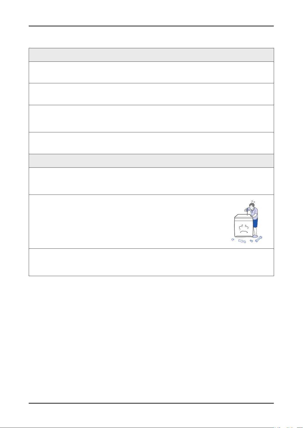
ࣃ Do not allow consumers to repair or service any part of the dishwasher themselves.
- This may result in personal injury and shorten the product life.
ࣃ If it seems that grounding is needed due to water or moisture, make sure to run grounding wires.
- Failure to do so may result in electric shock due to electric leakage.
2 _ Safety Instructions
Caution
Before Servicing
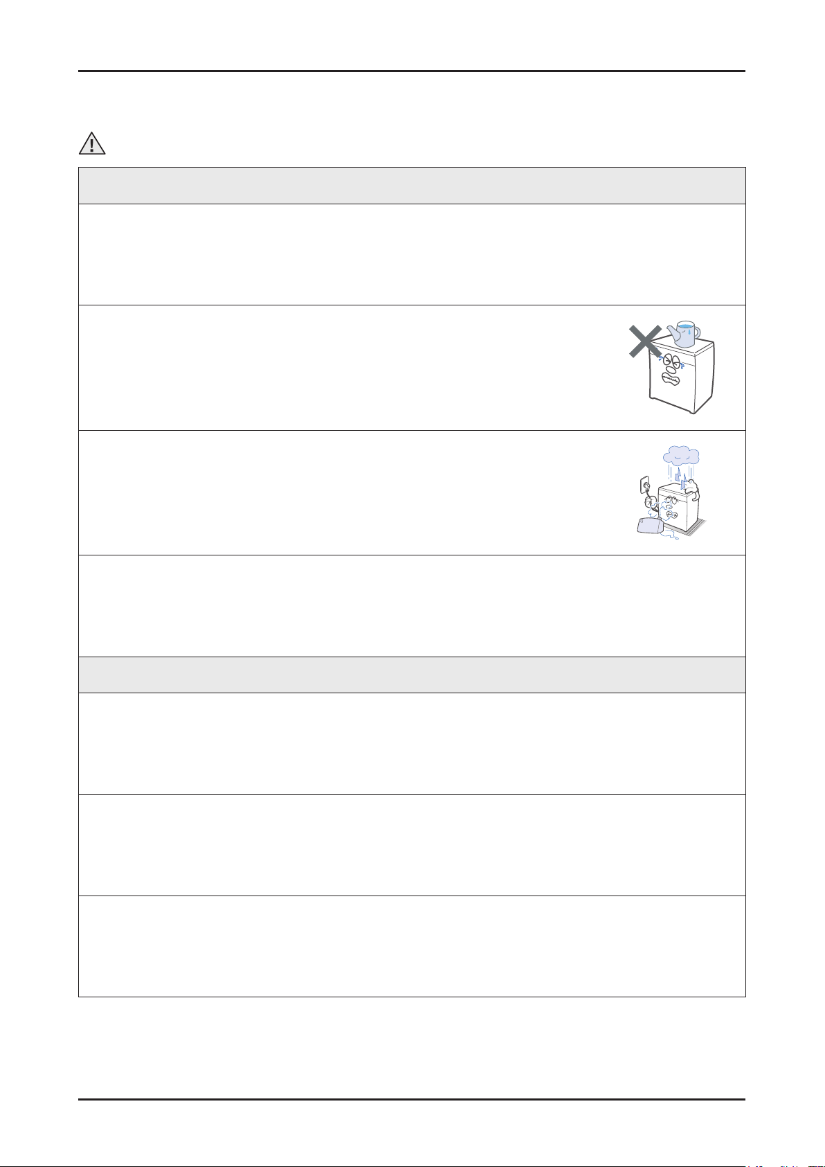
ࣃ Do not sprinkle water onto the dishwasher directly when cleaning it.
- This may result in electric shock or re, and may shorten the product life.
ࣃ Do not place any containers with water on the dishwasher.
- If the water is spilled, it may result in electric shock or re.
This will also shorten the product life.
ࣃ Do not install the dishwasher in a location exposed to snow or rain.
- This may result in electric shock or re, and shorten the product life.
ࣃ Do not press a control button using a sharp tool or object.
- This may result in electric shock or damage to the product.
During Servicing
ࣃ When connecting a wiring harness, make sure to seal it completely so no liquid can enter.
- Make sure that the connections are secured by slightly pulling on them.
ࣃ Check if there is any evidence that liquid has entered electric components or connections.
- If any liquid has entered into a part, replace it or completely remove any remaining moisture from it.
ࣃ If you need to place the dishwasher on its back for servicing purposes, place a support(s) on the oor and lay it
down carefully so the back is on the oor.
- Do not lay it down on its front or side. This may result in scratches to the surface or damage to the parts.
Safety Instructions _ 3
After Servicing
ࣃ Check the assembled status of the parts.
- They must be the same as before servicing.
ࣃ Check whether the product is level with the oor and secured to the cabinet and under
the counter.
- Vibrations can shorten the life of the product.
4 _ Safety Instructions

2. FEA TURES AND SPECIFICA TIONS
2-1. FEATURES
Features Description Remarks
New Waterwall cleaning system gets dishes sparkling everytime
Waterwall linear wash system
Target zone washing
Half load cycle: upper and lower
Third rack with ex tray
• High pressure, consistent wall of water cleans hard to reach places
• No need to pre-rinse
• Available on full or half cycle
Targeted wash for hard to clean pots and pans
• Control water pressure, temperature and time
• Select left target zone
Wash smaller loads without wasting water
• No need to wait until you have a full load
• Choose either upper or lower rack
• Saves on energy
Removable roll-up silverware tray for easy unloading
• Silverware lays at for better cleaning
• Perfect for oversized or hard to t items
• Easily roll up and remove for easy unloading
Adjustable racking system
Speed boost
Digital leakage sensor
Flexible design for more space
• Frees up more space on the top rack for tall and oversized items
Wash your dishes in less time
• Increased water pressure reduces wash time
• Perfect for everyday family dishes
Worry-free dishwashing
• Can sense a leak of only 1 1/2 ounces
• Shuts itself off before water can escape and cause oor damage
• Protects against water-related damage and provides peace of mind
Features and Specications _ 5
2-2. SPECIFICATIONS
Wash capacity 15 place settings
Type Dishwasher
Power Single-phased alternating current of 60Hz, 15A at 120V
Used water pressure 20 ~ 120 psi (140 ~ 830 kPa)
Wash type Waterwall Linear Wash & Rotating nozzle spray
Dry type Air diffusion condensing dry system
Power usage Main Pump : 96w (Waterwall operating), Heater : 1100w
Standard amount of used water 6.34 ~ 2.85 gallon (24 ~ 10.8 ℓ), Normal Cycle
Size (W×D×H) 23 ⅞" x 25" x 33 ⅞" inch (605 x 636 x 860 mm )
Accessory parts : User/Installation manual, Installation Kit, Kick Plate
6 _ Features and Specications
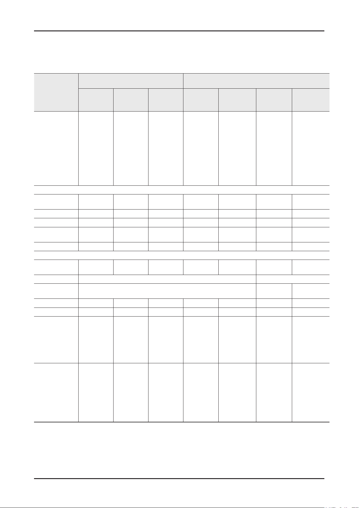
2-3. COMPARING SPECIFICATIONS WITH EXISTING MODELS
New model Model
Model
Photo
Panel Control
Control Type
Wine Rack
Handle Type
Basket Handle
Soil Detection
Sensors
Drying method
Basket Height
Adjustment
Leakage Sensor
Rail Type
Programs
Options
DW80M9550US/UGDW80M9960US/
UG
Silver/Black Silver/Black Silver/Black Silver
Touch Touch Touch Touch Touch Touch Touch
X X X O X X X
Pocket Pocket Pocket Pocket Pocket Bar
Blue + STS Blue + STS Blue + STS Blue + STS Gray Gray + STS Gray
O O O O O O O
O O O O O O O
“C” Rail “C” Rail “C” Rail Soft Rail “C” Rail “C” Rail “C” Rail
7
(Auto, Normal,
Heavy,
Delicate,
Express60”
Rinse only
Self Clean)
7
(Half load,
Zone Booster,
Speed Booster,
Hi-Temp Wash,
Sanitize, Delay
Start, Control
Lock)
7
(Auto, Normal,
Heavy,
Delicate,
Express60”
Rinse only
Self Clean)
8
(Half load,
Zone Booster,
Speed Booster,
Hi-Temp Wash,
Sanitize, Delay
Start, Control
Lock,Smart
Control)
DW80M9990UM
/US
Design Specications
Function Specications
AutoRelease system Air diffusion condensing
One-touch One-touch 2-stage
6
(Auto, Normal,
Heavy,
Delicate,
Express60, Self
Clean, Chef)
8
(Half load,
Zone Booster,
Speed Booster,
Hi-Temp Wash,
Sanitize, Delay
Start, Control
Lock,Smart
Control)
DW80J9945US
5
(Auto, Normal,
Heavy,
Delicate,
Express60”)
5
(Half Load
wash, Targeted
zone, Sanitize,
Dry+, Delay
start)
DW80J7550US/
UW/UG
Silver/Black/
White
5
(Auto, Normal,
Heavy, Delicate,
Express60”)
5
(Half Load wash,
Targeted zone,
Sanitize, Dry+,
Delay start)
DW80F800UWS
Silver
6
(Normal, Heavy,
Delicate, Pot &
Pans, Quick+,
Smart Auto)
6
(Delay Start,
Sanitize, Half
Load, Storm
Wash, Child
Lock, Start &
Drain)
DW80F600UTS
/UTB/UTW
Silver/Black/
Bar/Pocket/
Pocket
(Normal, Heavy,
Delicate, Smart
(Sanitize, Child
Lock, Delay
Start, Start &
White
4
Auto)
4
Drain)
Features and Specications _ 7
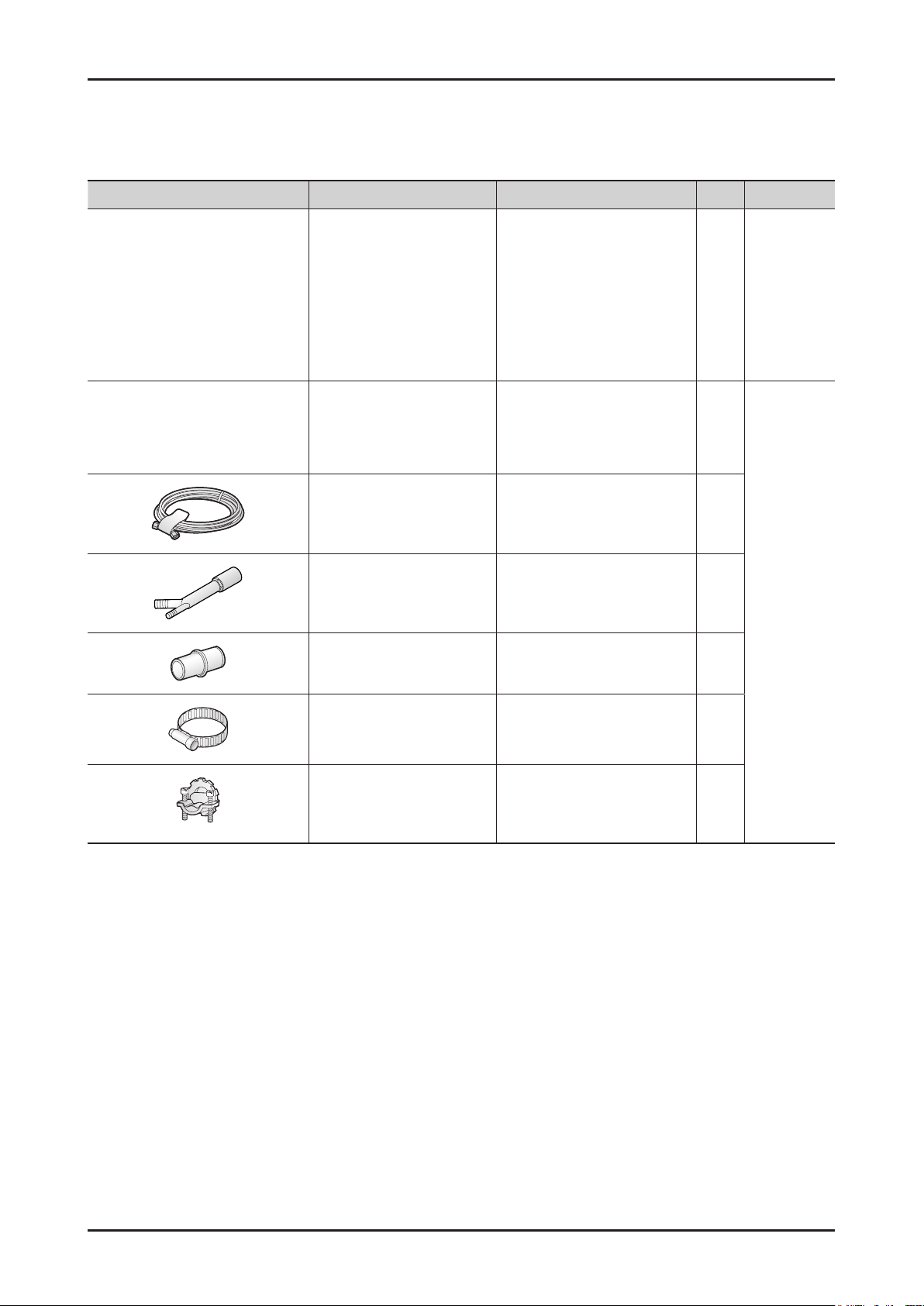
2-4. OPTIONS SPECIFICATIONS
Photo Item Code QTY Remarks
ASSY PACKING PARTS DD98-01019A 1
▫
FITTING (3/4”) - 1
90
WATER SUPPLY LINE
(Flexible STS supply line is
recommend)
Provided
with the
dishwasher
- 1
AIR GAP - 1
RUBBER CONNECTOR - 1
HOSE CLAMP - 1
STRAIN RELIEF - 1
Sold
separately
8 _ Features and Specications

3. DISASSEMBLY AND REASSEMBLY
3-1. TOOLS FOR REMOVAL AND REASSEMBLY
Tool image
No. Tool Type Remarks
➊
➊
➊
➊
➊
Adjustable Wrench
Open-end Wrench 1-7/16” Leg
Vice pliers
Others
(screwdriver, nipper, long nose pliers)
Nut Driver 10mm Heater bracket Nut
Common tools for servicing
Screwdriver - Philips, at, Torx T20, Small at
* Preparation for parts replacement
1. Take out the residual water inside the product.
(Drain the water by operating the drain pump)
2. Close the water supply valve.
3. Turn off the power & disconnect power cable.
You must turn off the circuit breaker connected to the product.
4. Pull out the unit from the sink and lay it on the oor.
Be careful of the drain hose when pulling out the unit.
Caution
When pulling out or laying the dishwasher down for service, it may be necessary to lower the height of the adjustable
legs to provide the clearance for the removal of the unit, prevent breaking the legs, or damaging the base of the unit.
Disassembly and Reassembly _ 9

3-2. PREPARATION FOR PARTS REPLACEMENT
1. Take out the residual water inside the product. (Drain the water by operating the drain pump)
2. Close the water supply valve.
3. Turn off the power. You must turn off the circuit breaker connected to the product.
4. Pull out the unit from the sink and lay it on the oor. Be careful of the drain hose when pulling out the unit.
Warning
Always turn off the electric power supply & water supply before servicing any electrical component, making ohmmeter
checks, or replacing any parts.
Caution
Before moving the unit, laying it down for service, or removing any parts for service be sure to drain as much of the water
from the unit as possible. Use a protective mat or towel to prevent damage to the oor or having any of the remaining
water spill on the oor.
All voltage checks should be made with a voltmeter having a full scale range of 250 volts or higher. After service is
completed, be sure all safety grounding circuits are complete, all electrical connections are secure, and all access
panels are in place.
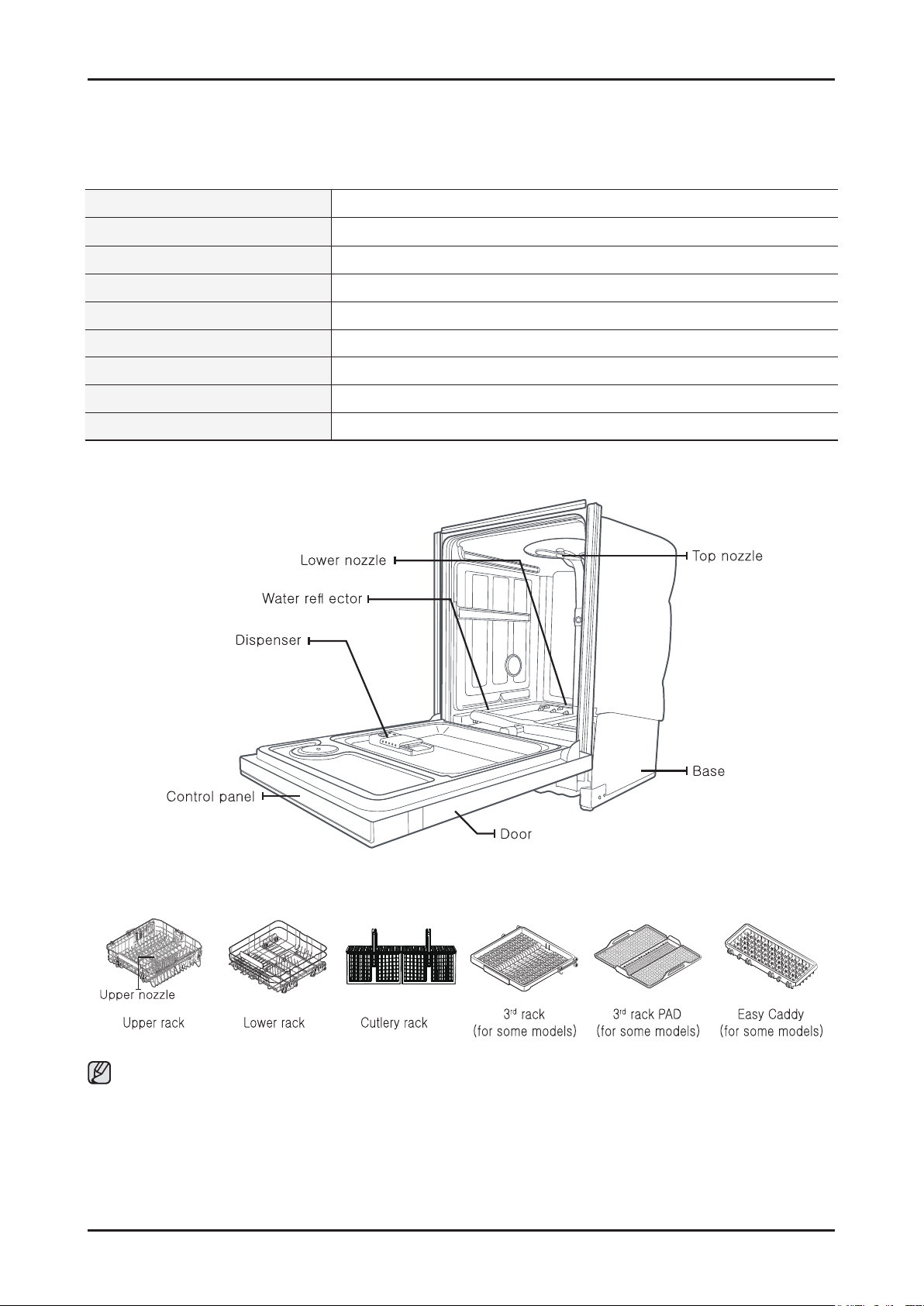
Before servicing, make sure to remove all items from inside of the dishwasher, including the wash racks.
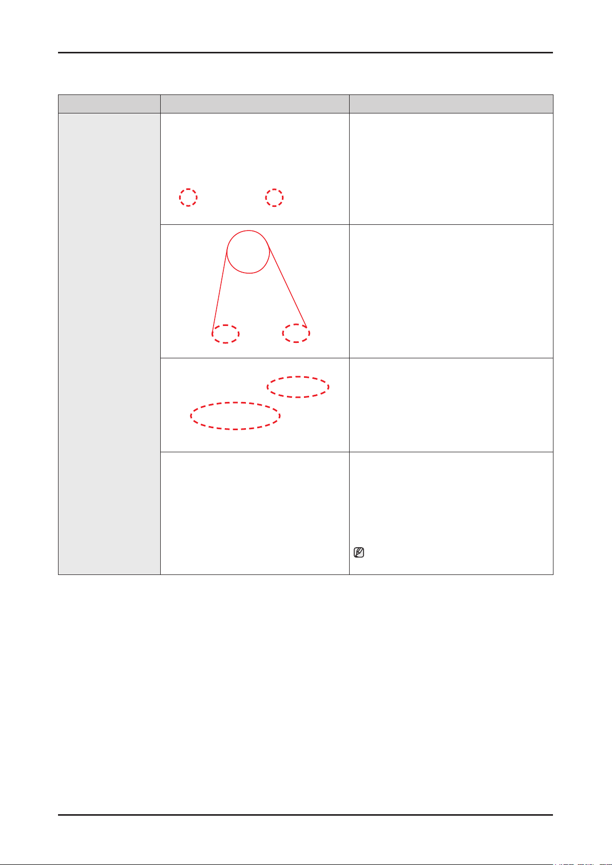
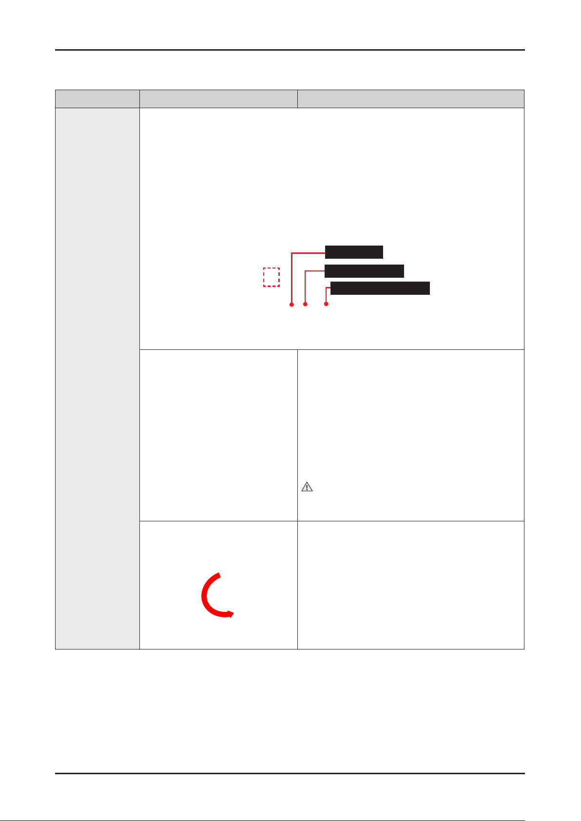
3-3. REMOVING THE UPPER RACK
Pull the upper rack towards the front and then remove it by lifting it up slightly and pulling it towards the front.
See the illustrations below.
Caution
While the upper rack is removable, it must be installed for the dishwasher to operate properly.
If you attempt to operate the dishwasher without the rack, noise will occur and the dishwasher will perform poorly.
Step 1. Step 2. Step 3.
10 _ Disassembly and Reassembly
Part Figure Description
Preparation:
• Make sure to disconnect the power.
1. Find Main PBA case below the door.
2. Remove two screws on the left and right.
3. Remove the cover from the Main PBA.
Main PBA
4. Remove the all wire connectors from Main
PBA.
- DW80M9960US/UG : 8 wire connectors
- DW80M9550US/UG : 7 wire connectors
5. Remove the two screws from the top left
and right of the main PBA.
6. Carefully put a screw driver in the gap.
Carefully angle the screwdriver to depress
the locking tabs that secure the Main PBA
to the housing and gently pull the Main PBA
from the housing.
When removing the Main PBA, lift the Main
PBA board up carefully.
Disassembly and Reassembly _ 11
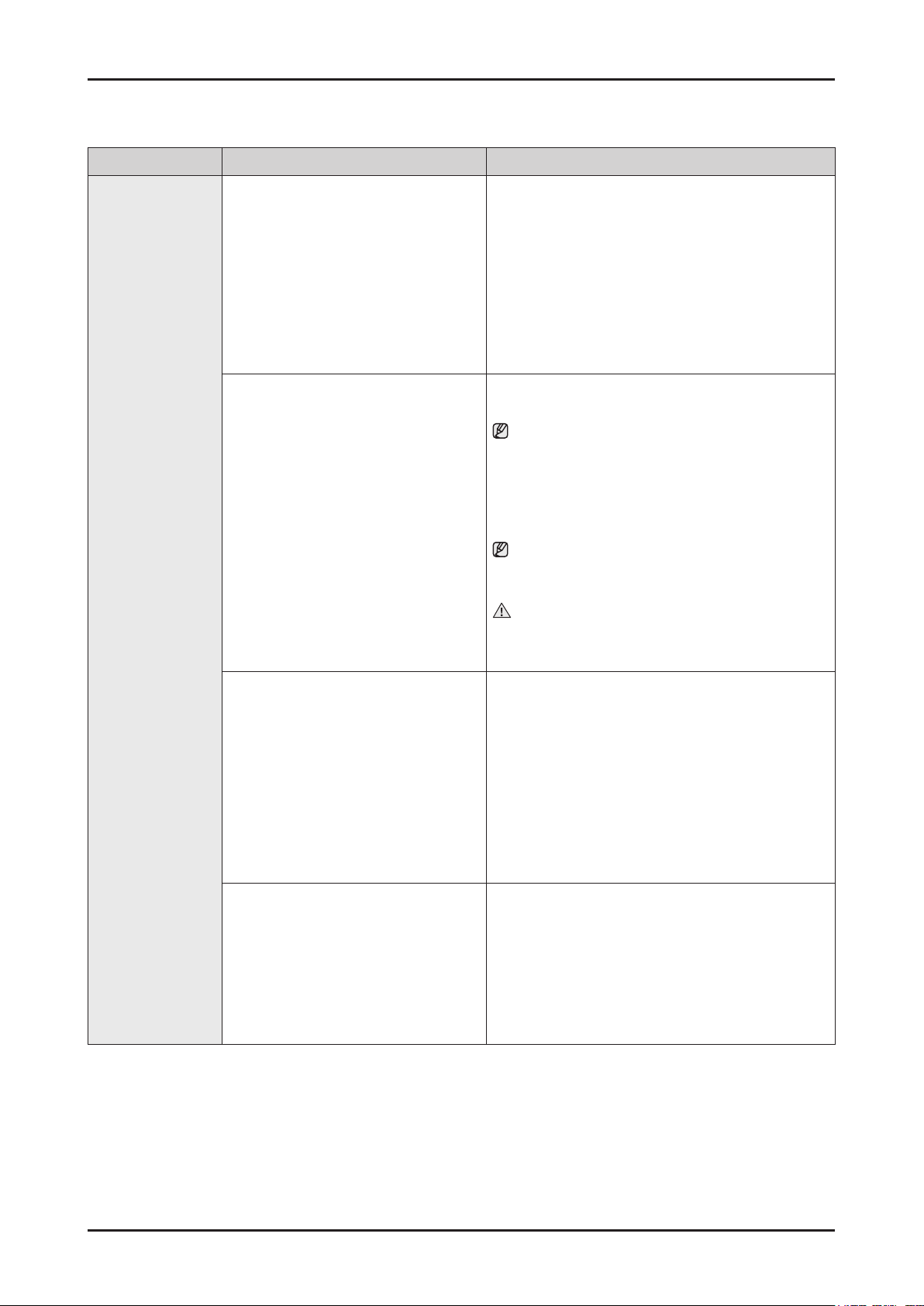
Part Figure Description
Preparation:
• Make sure to disconnect the power.
• Remove the lower basket in the dishwasher.
• Cover the Assy sump with a towel to prevent
losing screws.
1. Open the door completely to prevent losing
screws.
Before removing the parts, place a cushioned
mat on the oor to prevent the parts from being
scratched.
2. Remove the 12 screws (short one 8 pieces, long
one 4 pieces) which holding the door outer and
control panel in place.
After removing screws, make sure to hold the door
outer using your hand. This will prevent the door
from closing suddenly and harming you.
Door outer
Caution
Do not place the removed screws on the door
inner. They may fall into the sump assy.
3. Pull out the door outer carefully.
4. Separate wire connectors indicated by the red
arrows in the picture to the left and separate the
Wire from the Hook shown with red arrow.
- DW80M9960US/UG : 10 wire connectors
- DW80M9550US/UG : 8 wire connectors
5. Lay a mat on the oor to protect the Door and put
down the Assy door outer.
12 _ Disassembly and Reassembly

Part Figure Description
Preparation:
• Disassemble the Assy door outer.
1. Remove the two (2) screws from Assy Door outer.
2. Remove Sub PCB from panel control.
There is two hooks.
Panel control
3. Remove the Buzzer.
4. WIFI Module is xed to the panel control with
hook. Bend this hook than remove WIFI module.
Disassembly and Reassembly _ 13
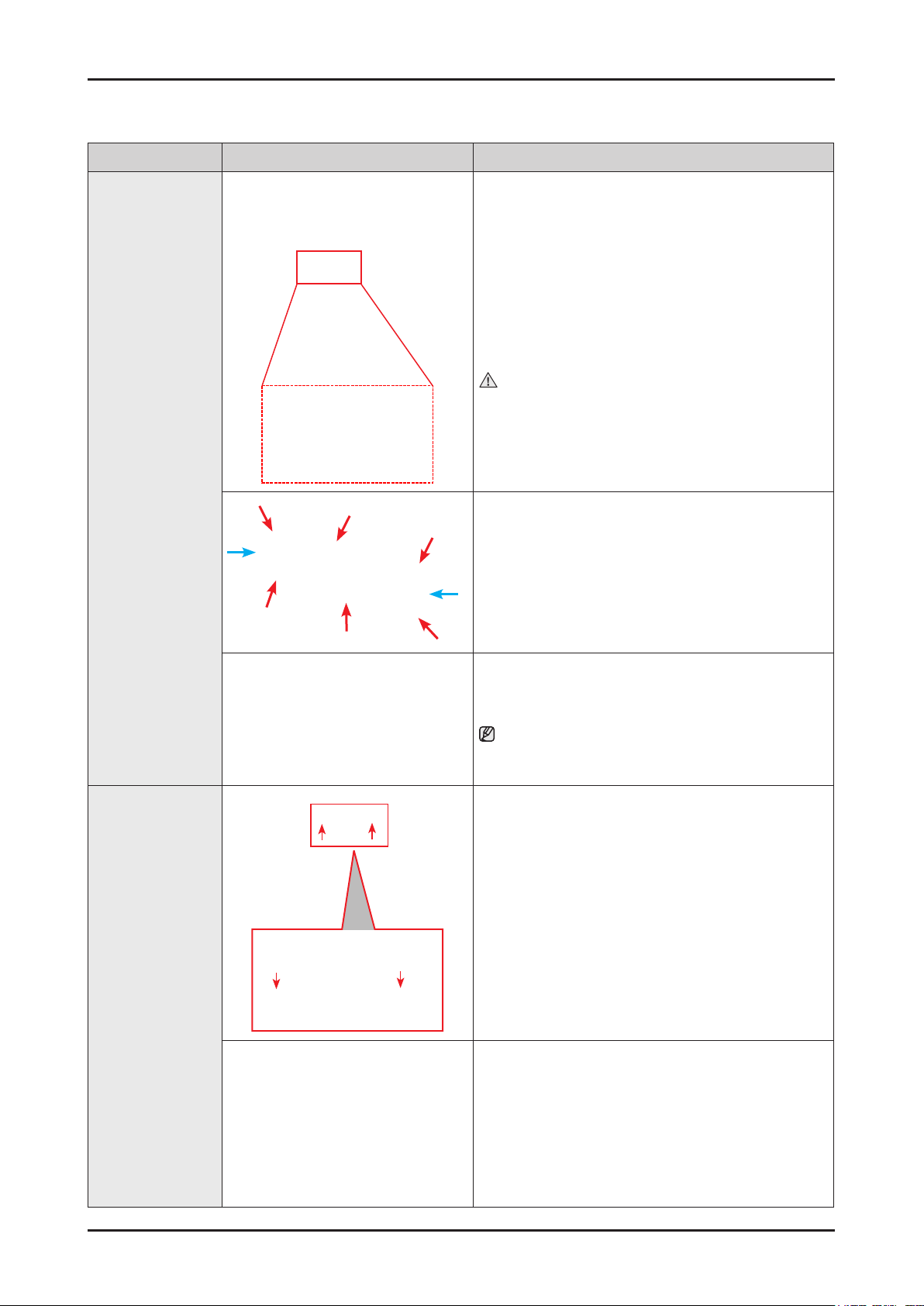
Part Figure Description
Preparation:
• Disassemble the door outer.
- Refer to the “door outer” disassembly section to
separate the door outer.
1. Remove the two(2) connectors from the dispenser.
Caution
Be careful not to break them during disassembly.
Dispenser - slide
2. The dispenser-slide is xed to the door inner with
several tabs. Use a at tip screwdriver to gently pry
the tabs.
Assy Module
(Pocket Light
Module)
3. Push it to the inside carefully.
Be careful as the tub front is sharp.
Preparation:
• Disassemble the Panel control.
- Refer to the “Panel control” disassembly section to
separate Panel control until step 1.
1. Remove Two (2) Screws which pointed by red
arrows from Assy window panel.
2. Disassemble Holder display PCB from Assy panel
control.
14 _ Disassembly and Reassembly
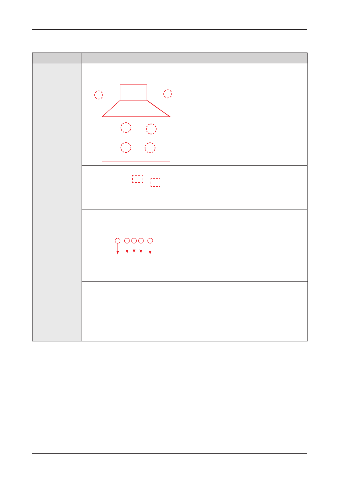
Part Figure Description
1. Remove the two(2) screws holding the trim-
up to the assy-tub.
2. Check and separate 2 hook of trim.
Lever door
Assy cover door
switch
Assy condenser
3 2 1 2 3
Assy condenser
Assy auto
door switch
Lever door
3. Separate two wire connector.
4. If you want to separate the Lever door from
Assy tub, remove the screw labelled ① in the
picture to the left.
If you want to separate Assy auto door switch
from Assy tub, remove the screws labelled ②
on the picture to the left.
If you want to separate Assy condenser from
Assy tub, remove the screws labelled ③ in the
picture on the left.
5. Refer to the picture on the left to remove the
parts.
Disassembly and Reassembly _ 15
Part Figure Description
1. Remove Holder-tub light by rotating.
(counterclockwise)
Assy Lamp LED
(for DW80M9990
Series)
2. Pull the Assy lamp LED to inside of tub.
16 _ Disassembly and Reassembly
Part Figure Description
1. Drain hose
2. Drain pump out
3. Assy guide water-sub
Preparation:
Assy Case Brake
• Make sure to disconnect the power, water supply,
and drain hose connections.
• Remove the upper, lower baskets and 3rd rack in
the dishwasher.
• Pull out the dishwasher carefully.
1. Remove the two(2) screws of the Housing Left.
2. Remove the housing left and make sure not to
damage the hooks on the bottom, outlined in the
blue box in the picture on the left.
Caution
Make sure to wear gloves when removing it.
Be careful as the steel plate is sharp and may cut you.
3. Remove cover brake by rotating.(counterclockwise)
Use a jig. If you do not have a jig, you can use
needle nose pliers.
(Be careful when removing the cover as it is easily
damaged.)
Disassembly and Reassembly _ 17
 Loading...