

Samsung DVM PLUS III HR, DVM PLUS III HR RD075VRXFA, DVM PLUS III HR RD100VRXFA, DVM PLUS III HR RD125VRXFA Installation Manual
Air Conditioner
installation manual
imagine the possibilities
Thank you for purchasing this Samsung product.
To receive more complete service, please
register your product at
www.samsung.com/register
DVM PLUS III HR
RDVRXF Series
PFSE
DB98-32805A(2)
DVM PLUS3 HR_IM_E_32805-2.indd 51 2011-11-11 오후 4:18:34

02_ safety information
safety information
SAFETY INFORMATION
SEVERE WARNING SIGNS
If you don’t follow the safety precautions, you may get the risk of serious wound or death.
The installation must be done by the installer or its service agent or a qualified
person in order to avoid a hazard.
• Installation by an unqualified person may cause a water leakage, electric shock or fire and
so on.
The electric work must be done by service agent or qualified persons according to
national wiring regulations and use only rated cable.
• Use certified power cable in the market suggested here and do electric work according
to installation manual otherwise, electric shock or fire may occur.
Install the outdoor unit correctly according to the installation manual.
• An incorrect installation may cause a water leakage, electric shock or fire and so on.
Manufacturer is not responsible for accidents due to incorrect installation.
When installing the unit in a small room, take measures in order to keep the
refrigerant concentration from exceeding allowable safety limits in the event
of a refrigerant leak.
• Excessive refrigerant concentration in a closed room can lead to oxygen deficiency.
Use certified parts in the market and supplied parts from the factory.
• If you don’t use the certified parts and tools, it can cause trouble to the air conditioner
and bring into injury.
Install the outdoor unit on a hard and even place that can support its weight.
• If the place cannot support its weight, the outdoor unit may fall down and it may cause injury.
Fix the outdoor unit securely on foundation to resist strong wind or
earthquake.
• If the outdoor unit is not properly fixed, it turns over and accidents may occur.
Fix power cable on fixture of outdoor unit securely not to be pulled out by
external force.
• If fixing is incomplete, it can cause trouble with a heat generation, electric shock or fire
and so on.
Before installing an air conditioner, please read this manual thoroughly to ensure that you know how to
safely and efficiently install a new appliance.
DVM PLUS III HR air conditioner uses R410A refrigerant.
- When using R410A, moisture or foreign substances may affect the capacity and reliability of the product.
Safety precautions must be taken when installing the refrigerant pipe.
- The designing pressure of the system is 4.1MPa. Select appropriate material and thickness according to the
regulations.
- R410A is a quasi-azeotrope of two refrigerants.
Make sure to charge with liquid phase when filling refrigerant.
If you charge gaseous refrigerant, it may affect the capacity and reliability of the product as a result of change
formation of the refrigerant.
Connect the indoor units for R410A refrigerant. Check whether the indoor units can be connected with the
product’s catalogue. (When incorrect indoor units are connected, they cannot operate normally.)
DVM PLUS3 HR_IM_E_32805-2.indd 2 2011-11-11 오후 4:18:07

safety information _03
ENGLISH
Arrange the cables between the indoor and outdoor unit after connecting.
Attach the cover securely so that the electrical component box cover does
not get loosen.
• If the cover is attached incompletely, it can cause trouble with a heat generation, electric
shock or fire of the terminal board.
Install MCCB and ELB according to installation manual.
• If you do not install the MCCB and ELB, electric shock or fire may occur.
The unit must be plugged into an independent circuit if applicable or
connect the power cable to the auxiliary circuit breaker. An all pole
disconnection from the power supply must be incorporated in the fixed
wiring with a contact opening of >3mm(1/8").
If any gas or impurities except R410A refrigerant come into the refrigerant
pipe, serious problem may occur and it may cause injury.
Make sure that there is no leakage after installation.
• Toxic gas may generate when refrigerant gas contacts with fire.
Leak test must be done using only Nitrogen gas.
When the product operates in heat mode during winter time, it operates
protection mode when the outdoor temperature drops below 0°C. Therefore,
supply the power during winter time. If the power is not supplied, compressor
protection mode will not operate and cause product malfunction.
Do not modify the product on your own.
• Potential risk of electric shock, fire, product failure or injury.
CAUTION SIGNS
If you don’t follow the safety precautions, you may get the risk of injury or loss of property.
Make sure of a earthing.
• Do not connect the earth wire to the gas pipe, water pipe, lighting rod or telephone wire.
If earthing is incomplete, electric shock or fire may occur.
Do not connect the heater to the outdoor unit and do not install altered duct
as you please.
• The capacity may reduce, electric shock or fire may occur.
Make sure that the condensed water dripping from the drain hose runs out
properly and insulate the drain pipe so that frost does not generate.
• Household goods may get wet if the drain pipe is not properly installed.
Install the indoor unit away from lighting apparatus using the ballast.
• If you use the wireless remote control, it may not operate normally.
Do not install the air conditioner in following places.
• The place where there is mineral oil or arsenic acid.
Those parts may get damaged due to burned resin.
The efficiency of the heat exchanger may reduce or the air conditioner may be out of
order.
• The place where corrosive gas such as sulfurous acid gas generates from the vent pipe
or air outlet.
The copper pipe or connection pipe may corrode and refrigerant may leak.
• The place where there is a machine that generates electromagnetic waves.
The air conditioner may not operate normally due to control system.
• The place where there is a danger of existing combustible gas, thinner or gasoline is
handled.
• The place where carbon fiber or flammable dust is.
• The place where like spa and shore.
DVM PLUS3 HR_IM_E_32805-2.indd 3 2011-11-11 오후 4:18:07
04_ safety information
safety information
CAUTION SIGNS
Install the power cable and communication cable of the indoor and outdoor
unit at least 1.5m(5') away from the electric appliances and install it at least
2m(6.5') away from the cable from the lightning rod.
• Noise may heard depending on the electric wave though the cables.
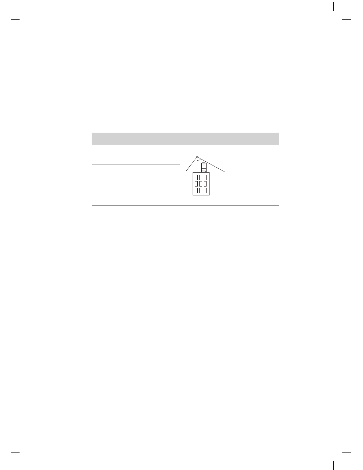
Install the outdoor unit within the angle of 25~55˚ depending on the building
height as below table.
Changes in DVM PLUS III HR comparing with conventional models(DVM PLUS II)
• Use R410A refrigerant.
• Check indoor units, distributor kits, etc which are connected with DVM PLUS III HR are
compatible with DVM PLUS III HR or not.
• Version of AVXE/NDA and higher is available.
• Make sure the combination method of outdoor units is different from DVM PLUS II.
• The length of maximum piping, level difference, the quantity of connectable indoor units,
the installation at the outdoor joints and the outdoor unit combinations are different from
the conventional models.
• Outdoor joint of gas side pipe should be installed horizontally due to the combination of
variable units when the height of the main pipe is lower than the outlet of the pipe of the
outdoor unit. The Installation of the liquid pipe and high pressure gas pipe are the same.
• If the pipe length between outdoor units becomes 2m(6.5') or more, install vertical trap
to upstream to prevent oil from getting accumulated in the pipes of the outdoor unit in
case of part load operation with the states which the last outdoor unit stops operating.
Building height Protective angle Remarks
Below 20m(65ft) 55˚
Below 40m(131ft)
35˚
Below 60m(196ft)
25˚
Building
Lightning rod
Protective angle: 25~55˚
DVM PLUS3 HR_IM_E_32805-2.indd 4 2011-11-11 오후 4:18:08

contents _05
ENGLISH
contents
PREPARING THE INSTALLATION
6
6 Shape of the outdoor unit
6 Accessories
6 Optional accessories
7 Outdoor unit combination
8 Selecting proper location for installation
9 Space requirements
9 Single installation
9 Group installation
10 Moving the outdoor unit
10 Detaching fasteners
11 Installing the outdoor unit
12 Anchor specifications
12 Intalling duct for horizontal exhaust discharge
13
Installing the outdoor unit in harsh environments
14
Installing the drain pipe
INSTALLING THE UNIT
15
15 Refrigerant piping works
15 Selecting the refrigerant pipe
16 Pipe selection for DVM PLUS III HR
17 Additional refrigerant charging
17 Equivalent length calculations
18 Keeping refrigerant pipe clean and dry
18 Brazing the pipe
19 Cutting or Flaring the pipes
20 Aligning the pipes
21 Free piping & wiring directions
22 Connecting the outdoor unit pipe
23 Piping works among outdoor units
24 The examples of the refrigerant pipe installation
25 Piping examples
26 Installing the branch joints
30 Wiring work
30 Manufacturer’s recommended specifications of
the circuit breaker and power cable
31 Power supply and communication cable
configuration
31 Specifications of the cable tube
32 Power wiring diagram
33 Selecting solderless ring terminal
33 Connecting the power terminal
34 Power cable arrangement
35 Grounding work
36 Performing the refrigerant gas leak test
37 Vacuum drying
38 Insulating the refrigerant pipe
38 Insulating the refrigerant
38 Selecting the insulation of the refrigerant pipe
38 Insulating the refrigerant pipe
39 Insulating the branch joint
COMPLETING THE INSTALLATION AND
COMMISSIONING
42
42 Charging refrigerant
42 Service valve work for gas pipe
44 Setting the option switches & function keys
44 Option switch of the outdoor unit
45 Key function
47 Completing the installation
48 Final checks and trial operation
48 Inspection before trial operation
49 Trial operation
DVM PLUS3 HR_IM_E_32805-2.indd 5 2011-11-11 오후 4:18:08
06_ preparing the installation
preparing the installation
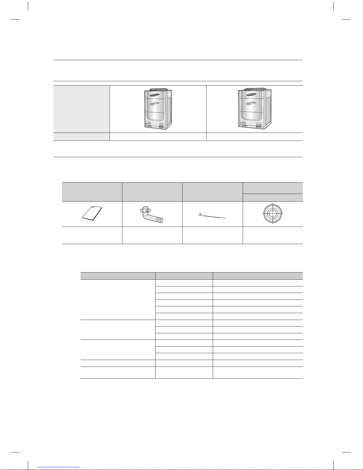
SHAPE OF THE OUTDOOR UNIT
Shape
Heat Pump RD075/100VRX RD125VRX
ACCESSORIES
• Keep supplied accessories until the installation is finished.
• Hand the installation manual over to the customer after finishing installation.
• The quantities are indicated in parentheses.
Optional accessories
• The following accessories are needed when installing the outdoor and indoor unit.
Installation manual (1) Drain plug (2) Cable tie (4)
Cap drain (2)
Remarks
- - -
For closing the drain hole
Type Model Capacity of outdoor unit
Y-joint
MXJ-YA1509 51MBH and below
MXJ-YA2512 51~138MBH
MXJ-YA2812 138~160MBH
MXJ-YA2815 160~240MBH
MXJ-YA3119 240~336MBH
MXJ-YA3819 336~438MBH
Y-joint
(Only for DVM PLUS III HR module)
MXJ-YA1500 80MBH and below
MXJ-YA2500 80~240MBH
MXJ-YA3100 240~468MBH
Header joint
MXJ-HA2512 160MBH and below
MXJ-HA3115 160~240MBH
MXJ-HA3819 Over 240MBH
Outdoor joint MXJ-T3819 12~30Ton
Outdoor joint
(Only for DVM PLUS III HR module)
MXJ-T3100 12~30Ton
• When the indoor units without EEV such as wall mounted and ceiling type are installed, it is
necessary to install distribution kits.
• It is necessary to install MCU when HR units are installed.
• Distribution kits and MCU should be purchased from the factory.
DVM PLUS3 HR_IM_E_32805-2.indd 6 2011-11-11 오후 4:18:09

preparing the installation _07
ENGLISH
OUTDOOR UNIT COMBINATION
• Make sure an indoor unit is compatible with DVM PLUS III HR
• Indoor units can be connected within a following table range.
• If the total capacity of the connected indoor units exceeds the suggested guideline, the indoor unit
cooling and heating capacity may decrease.
• Total capacity of the connected indoor units can be allowed to be from 50% to 130% over outdoor
capacity. (Depending on operation condition, the ratio of total capacity of the connected indoor units
over outdoor unit capacity should be considered carefully.)
0.5x∑ (Outdoor unit capacity) ≤ Total capacity of the connected indoor units ≤ 1.3x∑ (Outdoor unit
capacity)
• Up to 40 indoor units can be connected to an outdoor unit. The communication address of the indoor
unit sets following the quantity of the maximum indoor unit connected.
• The minimum capacity of the indoor unit is 6.0MBH.
Make sure to follow the table for combination installation of outdoor units.
1. Basic models
Classification
Capacity
(Ton)
Capacity
(HP)
Model
Total capacifities of the
connectable indoor units
(MBH)
Maximum number
of connectable
indoor units
Single unit
6 7.5 RD075VRXFA 36MBH ~ 93.6MBH 10
8 10 RD100VRXFA 48MBH ~ 124.8MBH 10
10 12.5 RD125VRXFA 60MBH ~ 156.0MBH 14
Classification
Capacity
(Ton)
Capacity
(HP)
Basic model
Total capacifities of the
connectable indoor units (MBH)
Maximum number of
connectable indoor units
RD075VRXFA RD100VRXFA RD125VRXFA
Module unit
12 15.0 2
72MBH ~ 187.2MBH
16
14 17.5 1 1
84MBH ~ 218.4MBH
18
16 20.0 2
96MBH ~ 249.6MBH
20
18 22.5 1 1
108MBH ~ 280.8MBH
24
20 25.0 2
120MBH ~ 312.0MBH
28
22 27.5 1 2
132MBH ~ 343.2MBH
30
24 30.0 3
144MBH ~ 374.4MBH
32
26 32.5 2 1
156MBH ~ 405.6MBH
34
28 35.0 1 2
168MBH ~ 436.8MBH
36
30 37.5 3
180MBH ~ 468.0MBH
40
CAUTION
2. Combinations
DVM PLUS3 HR_IM_E_32805-2.indd 7 2011-11-11 오후 4:18:09
08_ preparing the installation
preparing the installation
SELECTING PROPER LOCATION FOR INSTALLATION
Decide the installation location based on the following condition and obtain the user’s approval.
• Avoid a place that may disturb your neighbor. Noise may occur from the outdoor unit and the
discharged air may run into the neighborhood. (Be careful of the operation time in a residential area)
• Install the outdoor unit on a hard and even area that can support its weight.
• Choose a flat place that rainwater does not settle or leak.
• Choose a place avoiding strong winds.
• Maintain sufficient space for repairs and service.
• Choose a place where you can easily connect the pipes and cables to the indoor unit.
• Make sure that the condensed water dripping from the drain hose runs out properly and safely.
• When installing the outdoor unit near seashore, make sure it is not directly exposed to sea breeze.
If you can not find a adequate place without direct see breeze, protection wall should be constructed.
• Choose a place where there is no direct sunlight.
• Choose a place where it could not come into contact with snow and rain.
• Choose a place where flammable gas does not leak.
• Choose a place where the indoor and outdoor unit can be connected with a pipe.
• Install the indoor unit away from any interfering sources such as radio, computer, stereo
equipment and also select the place where the electrical wiring work can be possible.
- Especially keep the unit at least 3m(118-1/8") away from the electrical equipment in an
area electromagnetic waves generated and install the protection tube to protect the main
power cable and communication cable.
-
Make sure that there is no equipment electromagnetic waves generate. If not, malfunction of the
control system may occur due to the effect of the electromagnetic wave. (For example: The remote
control sensor of the indoor unit may not be received well of electronic lighting style fluorescent
lamps, such as fluorescent lamps are in the same space when using a remote control.)
•
Make sure to install the outdoor unit in a safe place where snowfall will not be obstructed. The frame
should be installed in a place where the air inlet and heat exchanger of the unit are not buried in the snow.
• Ventilation system will be better installed for the case of the refrigerant leakage in a closed
room even if R410A is nonpoisonous and noninflammable refrigerant.
• Install the railing around the outdoor unit to prevent falling when the unit is installed at high
place of roof on the building.
•
Avoid installing the units in places such as an exhaust pipe and ventilating opening exposed to corrosive
gas, oxides of sulfur, ammonia gas or sulfur gas herbicides. (These places need additional anticorrosive
treatments. Please contact manufacture to avoid corroding copper pipes or soldered parts)
•
According to the condition of power supply, electric noise or unstable voltage can occur malfunction of
electric parts or control system. (At the ship or places using power supply from electric generator… etc)
CAUTION
- Install the outdoor unit in a place (such as near buildings etc.) where it can be prevented from sea breeze
which can damage the outdoor unit.
-
If you cannot avoid installing the outdoor unit by the seashore, construct a protection wall around to block the sea breeze.
- Install the outdoor unit in a place where water can drain smoothly.
If you cannot find a place satisfying above conditions, please contact manufacturer.
Make sure to clean the sea water and the dust on the outdoor unit heat exchanger and spread
corrosion inhibitor on heat exchanger. (At least one time per one year.)
Protection wall should be constructed with a solid material such
as concrete to block the sea breeze and the height and the width
of the wall should be 1.5 times larger than the size of the outdoor
unit. Also, secure over 700mm(28") between the protection wall
and the outdoor unit for exhausted air to ventilate.
Outdoor
unit
Outdoor
unit
Sea
breeze
Sea
breeze
Sea
Sea
Protection
wall
Outdoor
unit
Sea
breeze
Sea
DVM PLUS3 HR_IM_E_32805-2.indd 8 2011-11-11 오후 4:18:09
preparing the installation _09
ENGLISH
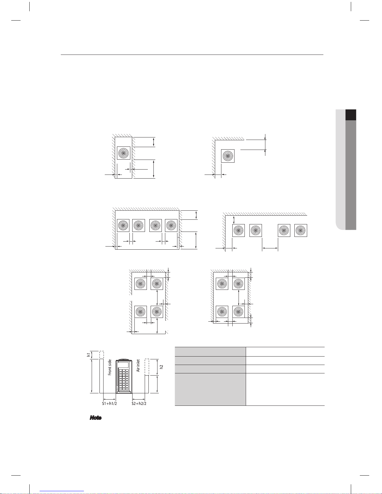
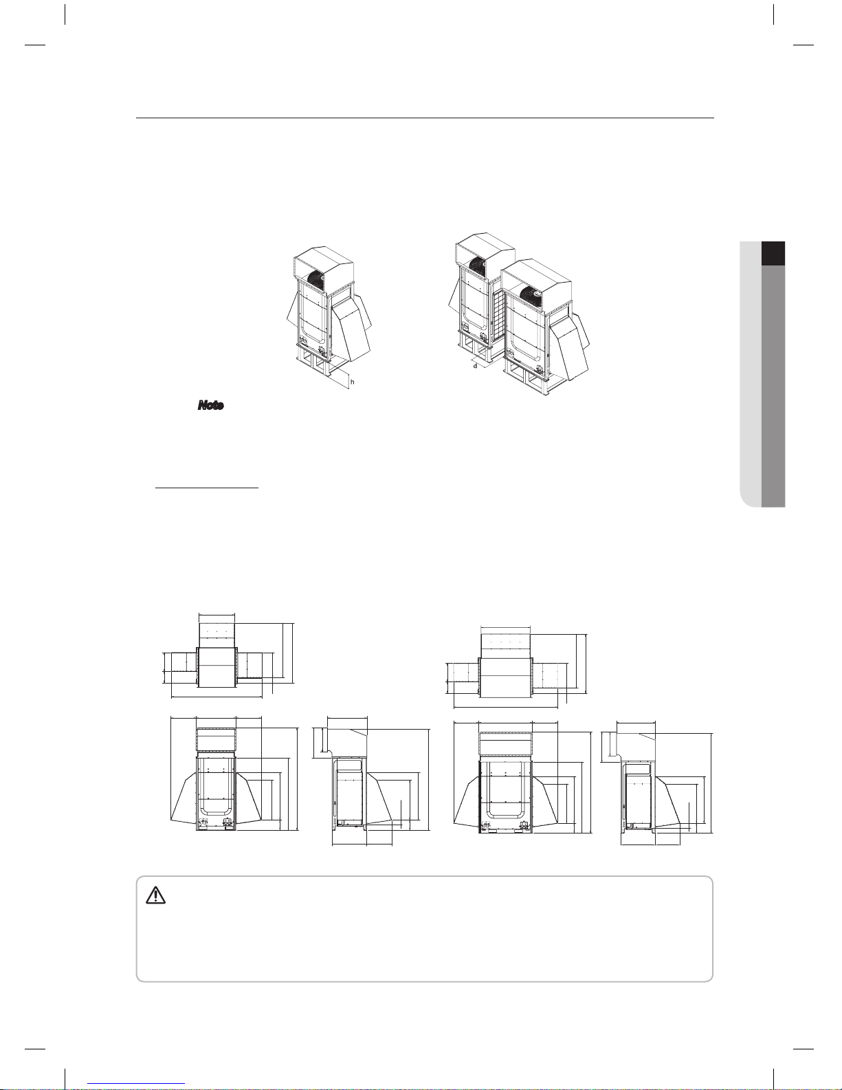
SPACE REQUIREMENTS
• The space suggested below is based on operating condition of outdoor temperature of 35°C(95°F).
If operating condition of outdoor temperature is higher than 35°C(95°F), try to have more space.
• Make sure to clear a passage for a person and air flow.
• Observe the clearances and dimensions as seen below when installing the outdoor unit.
• If you install several outdoor units at the same place, observe the space for ventilation and free airflow.
• If the space for ventilation is insufficient, the air conditioner may not generate performance designed.
Keep in mind that SAMSUNG logo is located on the front side of outdoor unit.
Single installation
Group installation
10(3/8) or more
300(12) or more[S2]
500(20) or more[S1]
Front
10(3/8)more
Unit : mm(inch)
200(8) or more
300(12)
or more
Wall height unrestricted
500(20)
1500(60)
Front wall height
1500(60) and less
Rear wall height
500(20) and less
Side wall height Height unrestricted
If the height of the wall
exceeds the above value,
more space should be
added to the front and
rear space individually.
Front : S1+h1/2,
Rear : S2+h2/2
20(3/4) or more
300(12)
or more
10(3/8)
or more
Front
600(24) or more
Front
20(3/4)
or more
500(20)
or more
20(3/4) or more
300(12)
or more
10(3/8)
or more
300(12)
or more
20(3/4)
or more
10(3/8)
or
more
Front
500(20) or more
Front
Unit : mm(inch)
Unit : mm(inch)
10(3/8) or more
10(3/8) or more
20(3/4) or more 20(3/4) or more
10(3/8)
more
500(20) or
more[S1]
300(12) or
more[S2]
Wall height unrestricted
300(12)
or more
200(8)
or more
400(16)
or more
Front
Front Front
Note
• The installation space mentioned above is minimum suggested clearance.
• To secure enough service space and performance of system, take account of more sufficient
space.
• The required minimum space between outdoor units for service and performance of system
is at least 100mm(4").
DVM PLUS3 HR_IM_E_32805-2.indd 9 2011-11-11 오후 4:18:10
10_ preparing the installation
preparing the installation
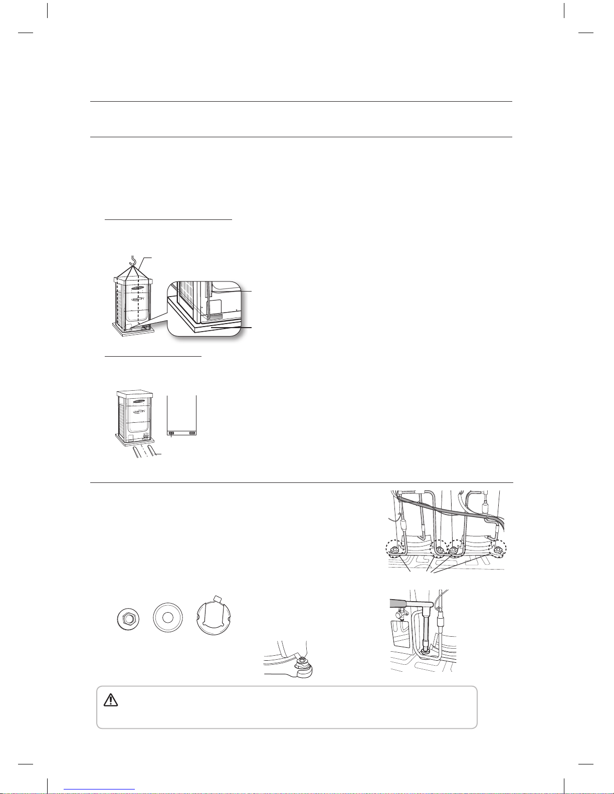
MOVING THE OUTDOOR UNIT
• Select the moving route in advance.
• Secure the strength of the carrying to resist against the weight of the outdoor unit while moving.
• Do not slant the product more than 30˚(86°F) when carrying it.
(Do not lay the product down sideways.)
• The surface of the heat exchanger is sharp. Be careful not to be get injury while moving and installing.
When moving with a crane or straps
• Fasten the wire rope as seen in the picture.
• To protect damage or scratches, insert a piece of cloth between the outdoor unit and the wire rope.
Fork part
Fork lift
When moving with a fork lift
• Insert the fork into the bottom of the outdoor unit carefully.
• Be careful that the fork does not damage the outdoor unit.
Wire rope/straps
Plate protection
cloth
Outdoor unit leg
DETACHING FASTENERS
• Open the bottom cabinet with screw driver.
The compressors are fastened with nuts in 4 places of only
following models.
RD125VRXF
• Detach nut washer, washer and stopper nut from compressors with a tool.
Stopper nutWasherNut washer
• Refasten the nut washer only.
• Pay your attention not to touch the copper pipes as detaching the fasteners.
• The stopper nut and washer should be removed. If this work is not conducted correctly,
the outdoor unit could vibrate and make noise.
Remove
CAUTION
DVM PLUS3 HR_IM_E_32805-2.indd 10 2011-11-11 오후 4:18:11
preparing the installation _11
ENGLISH
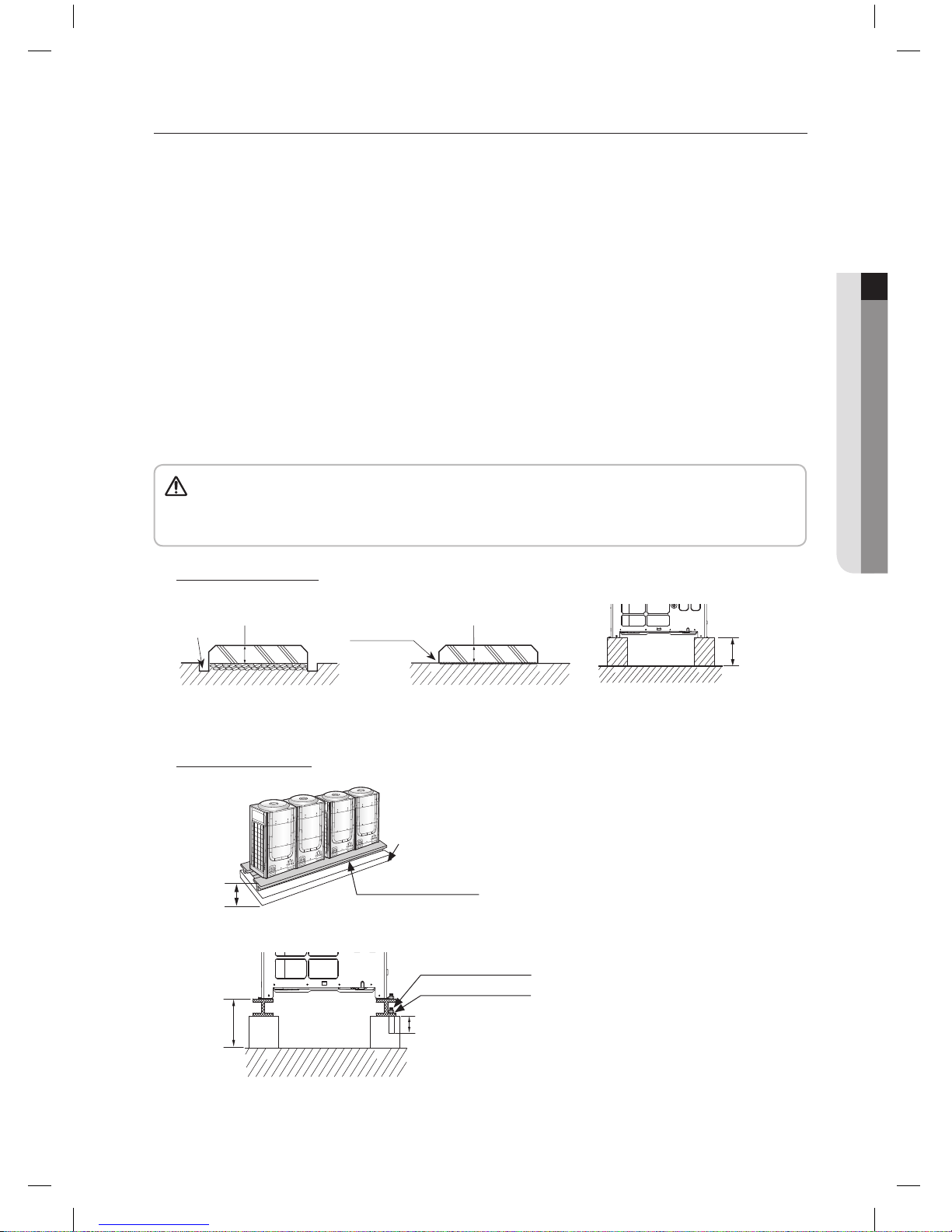
INSTALLING THE OUTDOOR UNIT
• Install the outdoor unit 200mm(8") higher than the base surface and install the drain hole to connect the
pipe to the drainage.
• The concrete foundation should be 1.5 times larger than bottom of the outdoor unit.
• Condensed water may be generated in heating operation. Pay attention to waterproof and drainage of
the concrete foundation where the outdoor unit is installed.
(An ice may form on the base surface in winter.)
• It is necessary to install wire mesh or steel bar when outdoor units are installed at soft foundation.
• When installing multiple outdoor units at the same place, install the H beam on the concrete foundation.
(When installing a number of outdoor unit, you can install it on the concrete foundation.)
• Install the H beam[150mm(6") x 150mm(6") x t10(3/8") : basic specification] or vibration absorption
frame to jut out from the concrete foundation.
• After installing the H beam or vibration absorption frame, apply corrosion protection.
• Install a square pad[t=20mm(3/4") or more] or vibration absorption frame to prevent vibration of the
outdoor unit delivering to the base surface when installing the concrete for the outdoor unit.
• Place the outdoor unit on the H beam or vibration absorption frame and fix it with the bolt, nut and
washer. (The bearing force is more than 3.5kN)
• Do not install the outdoor unit on a wood palette.
• Fix the outdoor unit securely to the base surface with anchor bolts.
• The manufacturer is not responsible for the damage occurred by not keeping standard of the
installation.
CAUTION
Base mount construction
200 or more
Drain hole
< When installing on the ground >
(Unit : mm)
200 or more
< When installing on the roof >
Install the outdoor unit
horizontally
on the ground
200 or more
200 or more
50
or more
Nut, Spring washer
Anchor bolt
Outdoor unit installation
Concrete
foundation
H beam or vibration
absorption frame
200 or more
DVM PLUS3 HR_IM_E_32805-2.indd 11 2011-11-11 오후 4:18:11
12_ preparing the installation
preparing the installation
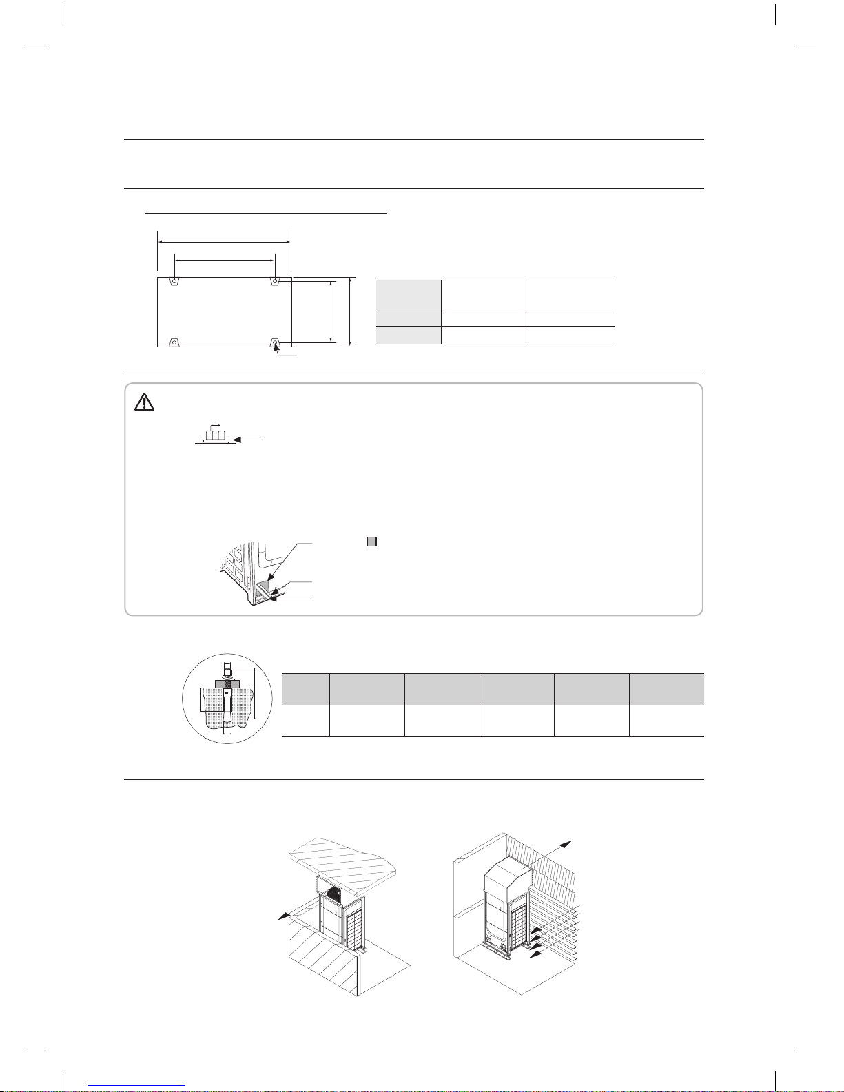
INSTALLING THE OUTDOOR UNIT
Anchor specifications
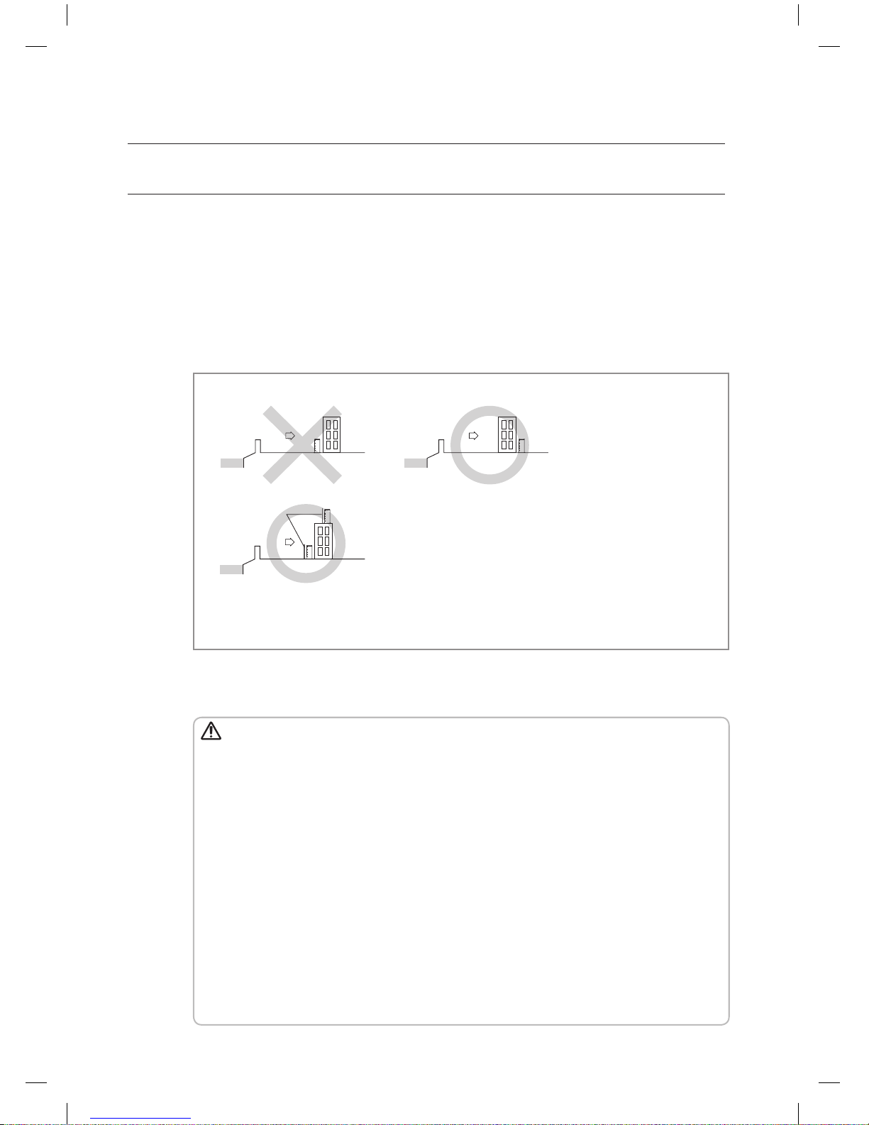
INSTALLING DUCT FOR HORIZONTAL EXHAUST DISCHARGE
• It is necessary to install an air-discharge duct(field supply) to direct exhaust from the fan horizontally if it
is difficult to provide a minimum space of 2m(6'7") between the air-discharge duct outlet and a nearby
obstacle as shown in the figure.
Model
RD075VRX
RD100VRX
RD125VRX
A
880(34-5/8) 1200(47-1/4)
B
738(29) 1058(41-5/8)
Outdoor unit base mount and anchor bolt position
• When tightening the anchor bolt
- Tighten the rubber washer to prevent the outdoor unit bolt connection part from corroding.
• When connecting the pipes
- Check the strength of the roof to install the outdoor unit and make sure to have a waterproof
floor of the roof.
- Make sure that a proper drainage system has been put in place around the outdoor unit.
- To protect the internal components of the outdoor unit, secure the pipework entrance to the
unit.
Rubber washer
Close the part.
(When the pipe is projected to the front side)
Liquid side pipe
Gas side pipe
Unit:mm(inch)
A
Anchor bolt
745(29-5/16)
765(30-1/8)
B
Size
Diameter of
drill bit (a)
Anchor
length (b)
Sleeve
length (c)
Insert
depth
Fastening
torque
M10 14mm(1/2") 75mm(3") 40mm(1-1/2") 50mm(2")
30N·m
a
b
c
m
Discharged air
Louver
Suction air
Upper floor
Discharged air
Ex) Balcony
Ex) Mechanical room
CAUTION
DVM PLUS3 HR_IM_E_32805-2.indd 12 2011-11-11 오후 4:18:12
preparing the installation _13
ENGLISH
INSTALLING THE OUTDOOR UNIT IN HARSH ENVIRONMENTS
• In abnormally harsh environments such as cold and/or windy areas, sufficient countermeasures to
guard against excessive wind and snow should be taken to ensure the unit’s correct operation.
• Snow-proof duct(field supply) should be fitted to the unit and direct exposure to the wind should be
avoided as much as possible.
• When the unit is expected to operate in cooling mode in condition under 10°C(50°F), in snowy areas,
in environments subject to strong winds or rain, install air inlet and outlet ducting as shown below.
When installing ducts
• Height of frame/foundation for snow damage prevention shall be twice as high as expected
snowfall, width of frame/foundation shall not exceed that of the unit.
• The frame/foundation shall be made of angle steel, etc., and designed so that snow and wind
slip through the structure. (If frame base is too wide, snow will be accumulated on it.)
• Install unit so that wind will not directly lash against openings of inlet and outlet ducts.
Note
The following problems may occur if proper countermeasures are not taken.
• The fan in the outdoor unit may stop running, causing the unit to be damaged.
• There may be no air flow.
• The condenser pressure may drop because of strong wind, and the indoor unit may freeze.
• The frame/foundation should be higher than expected snowfall.
• The foundation must be solid and the unit must be secured with anchor bolts.
• Be sure to install unit in a place strong enough to withstand its weight.
• When installing on a roof subject to strong wind, countermeasures must be taken to prevent the
unit from being overturned.
• Be sure to install unit in a place strong enough to withstand its weight.
CAUTION
<RD075/100VRX series> <RD125VRX series>
Unit : mm(inch)
782(30-3/4)
2000(78-3/4)
220
(8-5/8)
417
(16-3/8)
112(4-3/8) 557(21-7/8)
1207(47-1/2)
1318(51-7/8)
560(22) 880(34-5/8) 560(22)
880(34-5/8)
1050(41-3/8)
1588(62-1/2)
2256(88-7/8)
668(26-1/4)
532(21)
871(34-1/4)
765(30-1/8)
550(21-5/8)
220
(8-5/8)
105(4-1/8)
880(34-5/8)
1049(41-1/2)
2227(87-11/16)
252
(9-7/8)
765(30-1/8)
550(21-5/8)
417
(16-3/8)
252
(9-7/8)
1100(43-1/4)
2320(91-3/8)
112(4-3/8) 557(21-7/8)
1207(47-1/2)
1318(51-7/8)
560(22) 560(22)1200(47-1/4)
871(34-1/4)
220
(8-5/8)
880(34-5/8)
1050(41-3/8)
1588(62-1/2)
2256(88-7/8)
668(26-1/4)
532(21)
105(4-1/8)
220
(8-5/8)
880(34-5/8)
1049(41-1/4)
2226(87-10/16)
DVM PLUS3 HR_IM_E_32805-2.indd 13 2011-11-11 오후 4:18:14
14_ preparing the installation
preparing the installation
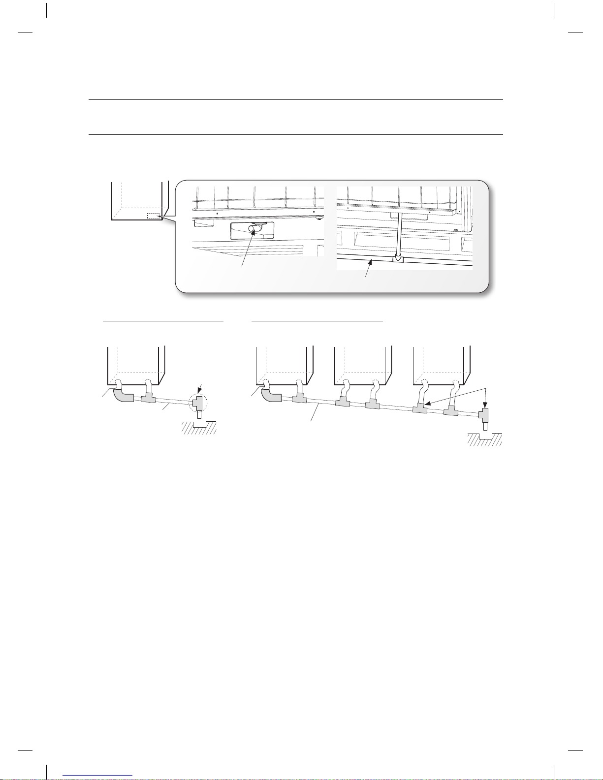
INSTALLING THE DRAIN PIPE
• Insert the provided drain plug at the 2 sides of the bottom of the unit and then connect the drain pipe.
• Install the drain pipe at the rear side of the unit to get a sufficient space for repairs and service.
• Do not install a trap on the pipe.
And, install the drain pipe horizontally with a slope of 1/50 or more.
• Insulate the drain pipe and drain plug with insulation over 10t.
• Install heating device to the drain pipe to prevent it from being frozen.
Install the safety equipment for a heating appliance.
When installing single outdoor unit
Outdoor unit
(Rear side)
More than
1/50 slope
Open to air
Drain
plug
Outdoor unit
(Rear side)
More than 1/50 slope
Open to air
Drain
plug
Outdoor unit
(Rear side)
Outdoor unit
(Rear side)
When installing multiple outdoor units
Outdoor unit
(Rear side)
Drain plug
Drain pipe
DVM PLUS3 HR_IM_E_32805-2.indd 14 2011-11-11 오후 4:18:14
installing the unit _15
ENGLISH
installing the unit
REFRIGERANT PIPING WORKS
• The piping length between the outdoor unit and the indoor unit may not exceed the allowable piping length.
• The pressure of the R410A is high. Use only certified refrigerant pipe and follow the installation method.
• Use clean refrigerant pipe which there is no harmful ion, oxide, dust, iron content or moisture inside pipe.
• Use tools and accessories fit on R410A.
Selecting the refrigerant pipe
Tool Work If compatible with conventional tool
Pipe cutter
Refrigerant pipe work
Pipe cutting
Compatible
Flaring tool Pipe flaring
Refrigerant oil
Apply refrigerant oil on flared
part
Ester series oil, alkali
benzene oil or synthetic oil
Torque wrench Connect flare joint with pipe
Compatible
Pipe bender Pipe bending
Nitrogen gas
Air tightening test
Inhibition of oxidization
Brazing tool Pipe brazing
Gauge manifold
Air tightening test ~ additional
refrigerant charging
Vacuuming, charging and
checking operation
Exclusive
Refrigerant charging hose
Vacuum pump Vacuuming unit
Use one which has a check
valve and 5 torr degree of
vacuum.
Electronic scale Compatible
Gas leak detector Gas leak test Exclusive
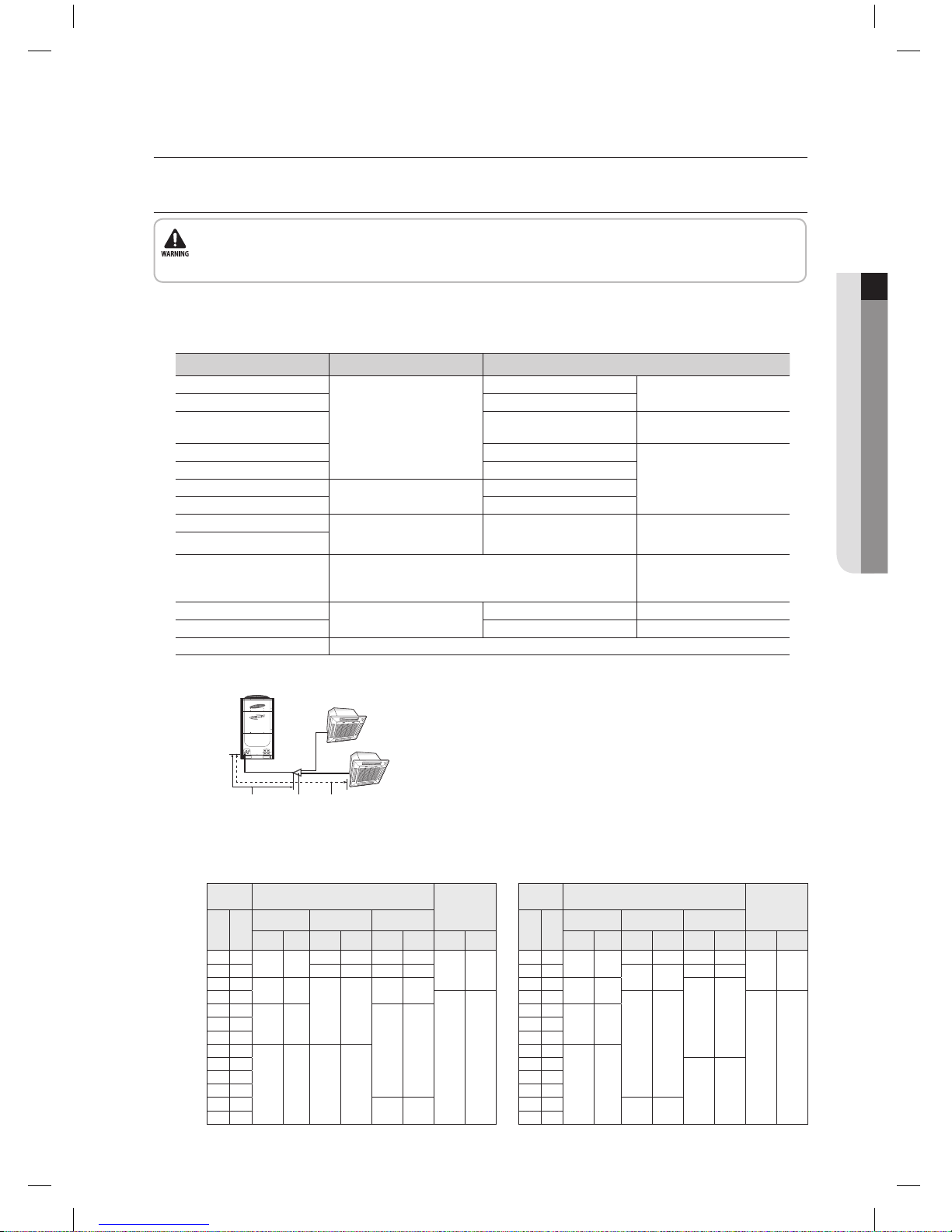
Flare joint Use indoor unit’s only
Main pipe Equivalent pipe length between outdoor
unit and the farthest indoor unit
Main pipe : from outdoor unit to the first branch joint.
First branch
joint
Select the main pipe of outdoor units with the following
table.
Select the main pipe of outdoor units with the following table
when if the farthest indoor unit’s length is over 90m(295').
• When installing, make sure there is no leakage. When recovering the refrigerant, ground the compressor first before removing the
connection pipe. If the refrigerant pipe is not properly connected and the compressor works with the service valve open, the pipe inhales
the air and it makes the pressure inside of the refrigerant cycle abnormally high. It may cause explosion and injury.
Outdoor
unit
Pipe size (O.D)
Oil balancing
pipe size
Ton HP
Liquid Gas H.P. Gas
mm inch mm inch mm inch mm inch
6 7.5
Ø12.70 Ø1/2
Ø22.23 Ø7/8 Ø19.05 Ø3/4
8 10
Ø28.58 Ø1 1/8
Ø22.23 Ø7/8
10 12.5
Ø15.88 Ø5/8
Ø28.58 Ø1 1/8
12 15
Ø34.93 Ø1 3/8
Ø6.35 Ø1/4
14 17.5
Ø19.05 Ø3/416 20
18 22.5
20 25
Ø22.23 Ø7/8
22 27.5
Ø34.93 Ø1 3/8
24 30
26 32.5
28 35
Ø41.28 Ø1 5/8
30 37.5
Outdoor
unit
Pipe size (O.D)
Oil balancing
pipe size
Ton HP
Liquid Gas H.P. Gas
mm inch mm inch mm inch mm inch
6 7.5
Ø9.52 Ø3/8
Ø19.05 Ø3/4 Ø15.88 Ø5/8
8 10 Ø22.23 Ø7/8 Ø19.05 Ø3/4
10 12.5
Ø12.70 Ø1/2
Ø28.58 Ø1 1/8
Ø22.23 Ø28.58
12 15
Ø6.35 Ø1/4
14 17.5
Ø15.88 Ø5/8
Ø28.58 Ø1 1/8
16 20
18 22.5
20 25
Ø19.05 Ø3/4 Ø34.93 Ø1 3/8
22 27.5
24 30
26 32.5
28 35
Ø34.93 Ø1 3/8
30 37.5
DVM PLUS3 HR_IM_E_32805-2.indd 15 2011-11-11 오후 4:18:15
 Loading...