

Samsung DVD-VR320/XEE, DVD-VR320/XEU, DVD-VR320/SED, DVD-VR320/XEG, DVD-VR320/XET User Manual
...
DVD-VCR Recorder COMBO
Chassis: K2
DVD-VR320/XEU, XEF, XEB, SED, XEN,
XEE, XEG, XET, COM, EUR,
XEV, XEH, XEC, XEO
SERVICE
Multi format recording
DVD-RAM / DVD-RW / DVD-R
Multi format playback
DVD / DVD-RAM / DVD-RW / DVD-R
CD / CD-R / CD-RW / MP3 / JPEG
Rcording mode
XP(1Hour) / SP(2Hour) / LP(4Hour) / EP(6~8Hour)
Progressive scan
Both DVD & VCR
Automatic Chapter Product ON
Manual
DVD-VCR RECORDER COMBINATION
Merit & Character regarding Product
SERVICE MANUAL
DVD-VR320
ELECTRONICS
© Samsung Electronics Co., Ltd. MAR. 2005
Printed in Korea
AK82-00795A
This Service Manual is a property of Samsung Electronics Co.,Ltd.
Any unauthorized use of Manual can be punished under applicable
international and/or domestic law.

CONTENTS
1. Precautions (1-1 ~ 1-6)
1-1 Safety Precaution (1-1)
1-2 Servicing Precautions (1-3)
1-3 ESD Precautions (1-4)
1-4 Handling the optical pick-up (1-5)
2. Product Specification (2-1 ~ 2-6)
2-1 Product Specification (2-1)
2-2 Chassis Product Specification (2-2)
2-3 Option Product Specification (2-6)
3. Software Update (3-1 ~ 3-4)
3-1 Drive Firmware Update (3-1)
3-2 Flash Update (3-3)
4. Alignment and Adjustments (4-1 ~ 4-12)
4-1 VCR Adjustment (4-1)
4-2 VCR Mechanical Adjustment (4-4)
5. Disassembly and Reassembly (5-1~5-22)
5-1 Cabinet and PCB (5-1)
5-2 Circuit Board Locations (5-3)
5-3 VCR Deck Parts Locations (5-4)
5-4 VCR Deck (5-7)
5-5 The table of cleaning, Lubrication and replacement time about principal parts
(5-21)
6. Trouble Shooting (6-1 ~ 6-36)
7. Exploded View and Parts List (7-1 ~ 7-8)
7-1 Cabinet Assembly (7-2)
7-2 VCR Mechanical Parts (Top Side) (7-4)
7-3 VCR Mechanical Parts (Bottom Side) (7-6)
8. Electrical Parts List (8-1 ~ 8-18)

9. Block Diagrams (9-1 ~ 9-10)
9-1 All Block Diagram (9-2)
9-2 AIC1(PCM1753) Audio DA Block Diagram (9-3)
9-3 AIC9(PCM1802) Audio AD Block Diagram (9-4)
9-4 DIC1(DMN8602) A/V Codec Block Diagram (9-5)
9-5 DIC3(29DL323) Flash memory Block Diagram (9-6)
9-6 IC801(TEA6425)Typical Application Block Diagram (9-7)
9-7 TIC1(TW9909) Video Decoder Block Diagram (9-8)
9-8 U23(M13S128168A) DRAM Block Diagram (9-9)
10. Wiring Diagram (10-1 ~ 10-2)
11. PCB Diagrams (11-1 ~ 11-8)
11-1 VCR Main PCB (11-2)
11-2 DVD Main PCB (11-4)
11-3 Jack PCB (11-6)
11-4 Function PCB (11-8)
12. Schematic Diagrams (12-1 ~ 12-20)
◆Block Identification of Main PCB (12-2)
12-1 S.M.P.S (VCR Main PCB) (12-3)
12-2 Power (VCR Main PCB) (12-4)
12-3 Secam (VCR Main PCB) (12-5)
12-4 A/V (VCR Main PCB) (12-6)
12-5 Hi-Fi (VCR Main PCB) (12-7)
12-6 F-Timer (VCR Main PCB) (12-8)
12-7 OSD (VCR Main PCB) (12-9)
12-8 System Control / Servo (VCR Main PCB) (12-10)
12-9 A/V Switching (Main PCB) (12-11)
12-10 A2/NICAM (Main PCB) (12-12)
12-11 I/O (Main PCB) (12-13)
12-12 Audio (Jack PCB) (12-14)
12-13 Video (Jack PCB) (12-15)
12-14 OSD/VPS/PDC (Jack PCB) (12-16)
12-15 Front (Jack PCB) (12-17)
12-16 Connection (Jack PCB) (12-18)
12-17 TM (Jack PCB) (12-19)
CONTENTS

13. Operating Instructions and Installation (13-1 ~ 13-74)
14. Circuit Operating Descriptions (14-1 ~ 14-50)
14-1 Power (14-1)
14-2 AV Codec (14-4)
14-3 SERVO (DVP Multi Drive) (14-7)
14-4 Video Input (14-9)
14-5 Video Output (14-11)
14-6 Audio (14-13)
14-7 Tuner (14-14)
14-8 IF (14-15)
14-9 VCR System Control (14-16)
14-10 VCR Servo (14-26)
14-11 VCR Video (14-30)
14-12 Hi-Fi Audio (14-38)
14-13 Linear Audio (14-43)
14-14 TM (14-46)
14-15 OSD (14-49)
15. Reference Information (15-1 ~ 15-38)
15-1 VCR Deck Operating Description (15-1)
15-2 Basic Configuration of Mechanism (15-1)
15-3 Main Mechanism and Functions (15-2)
15-4 Basis of the Mechanism (15-4)
15-5 System Control (15-9)
15-6 System Control and Mechanical Operations (15-10)
15-7 Introduction to DVD (15-26)
15-8 DVD-Video Fromat (15-28)
15-9 About IEEE-1394 (15-34)
CONTENTS

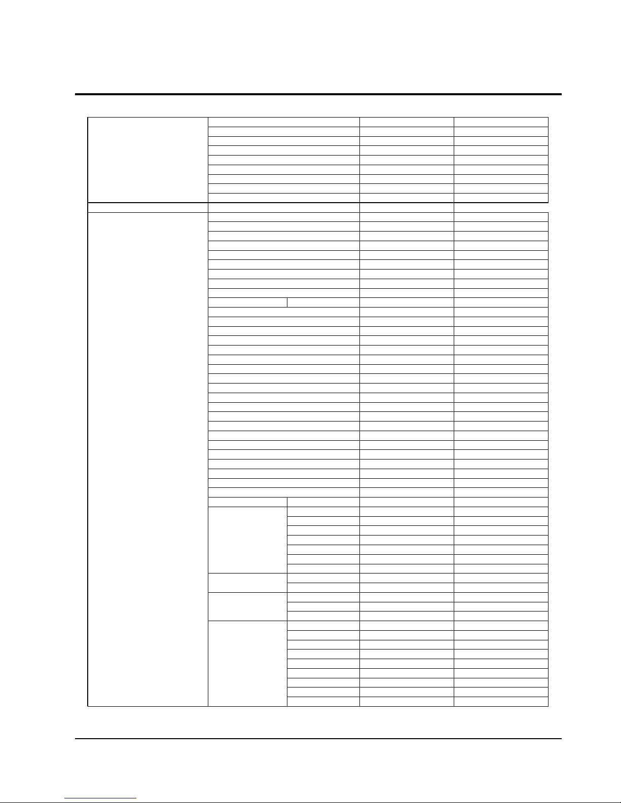
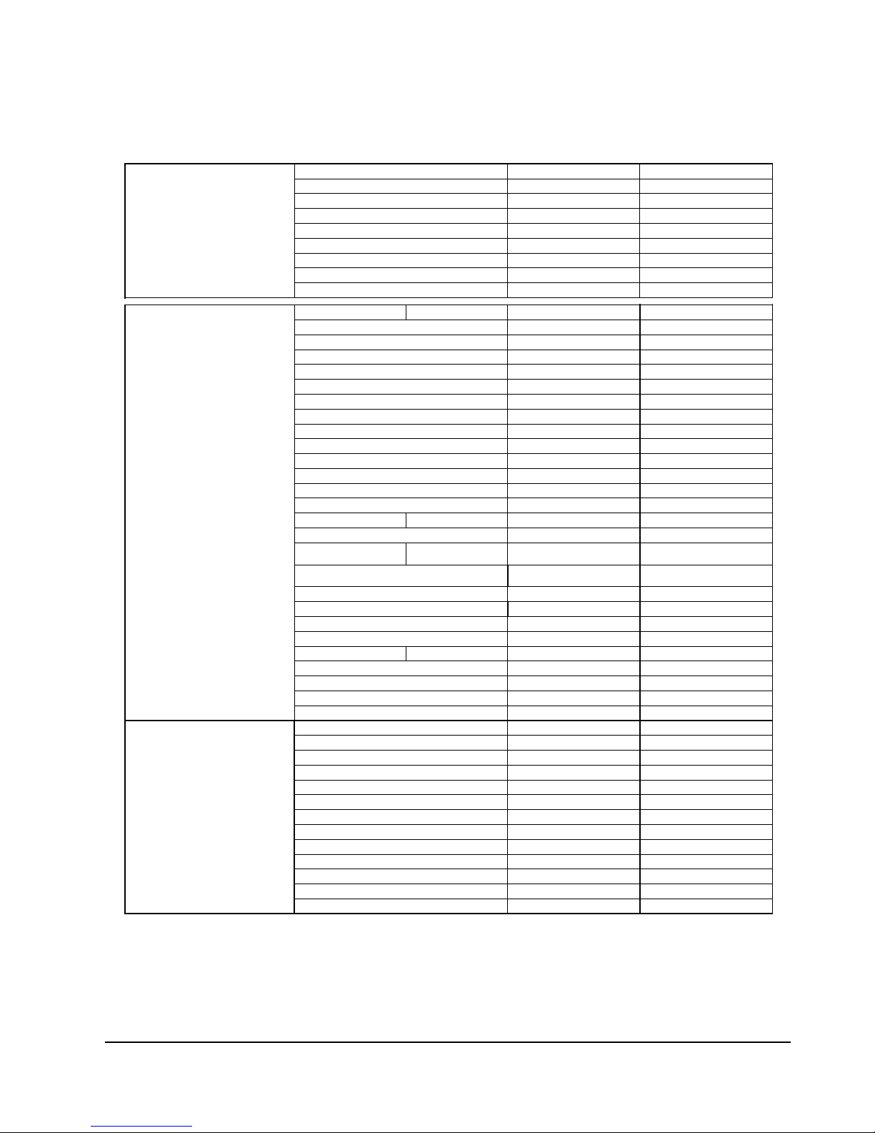
Product Specification
Samsung Electronics 2-1
Power requirements AC 220-240V, 50Hz
Power consumption 45Watts
General
Weight 5.3Kg
Dimensions 430(W) x 321(D) x 84in(H)
Operating temp +5°C to + 35°C
Other conditions Keep level when operating. Less than 75% operating humidity
Video input(Rear) Euro Scart socket : 1.0 V p-p (unbalanced) 75ohm
Input Audio input(Rear) Euro Scart socket : -8dBm, 47Kohm unbalanced
Front input RAC jack, DV, S-Video
Audio (DVD, VCR) RAC jack, Euro Scart socket, Audio L/R
Output
Audio (DVD, Only) Digital audio out OPTICAL COAXIAL
Video (DVD, VCR) RCA jack, Euro Scart socket(Composite, RGB), S-Video Out, COMPONENT
Tape format VHS type video tape
Colour system PAL
Tuning System SECAM-L, B/G
VCR Video S/N Above 43dB (standard recording)
Resolution Above 240 lines (standard recording)
Audio S/N Above 68dB (Hi-Fi), 39dB(Mono)
Audio frequency characteristics 20Hz-20KHz(Hi-Fi)
Picture compression format MPEG-II
Audio compression format Dolby AC-3 256kbps
DVD Recording Qallity XP(8Mbps), SP(4Mbps), LP(2Mbps), EP(1.2/0.8Mbps)
Video S/N Ratio Min. 50dB at standatd tecording
Audio S/N Ratio Min. 75dB
Audio frequency characteristics 20Hz ~ 20KHz
2. Product Specification
2-1 Product Specification
Product Specification
2-2 Samsung Electronics
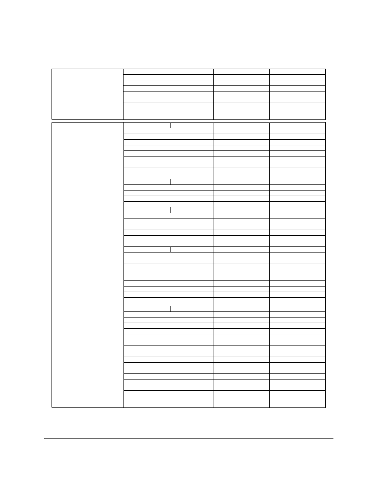
2-2 Chassis Product Specification
Basic Basic
Samsung Samsung
DVD-VR300E/XEU DVD-VR320/XEU
UK UK
SEUK SEUK
English English
GB/FR/IT/ES/DE/NL GB/FR/IT/ES/DE/NL
SUWON SESK
CE , SEMKO CE , SEMKO
22
No/Quasi-PAL No/Quasi-PAL
No/No No/No
Yes/Yes Yes/Yes
No/No No/No
No/No No/No
PAL Recording & Playback PAL Recording & Playback
No/No No/No
PLAYBACK
Yes Yes
Yes Yes
Yes Yes
Yes Yes
-
Yes Yes
Yes Yes
Yes Yes
-
Yes Yes
NO yes
NO yes
Yes Yes
Yes(1000Folder) Yes(1000Folder)
NO yes
NO DIVX
-
-
RECORDING
DVD-RAM Yes Yes
DVD-R Yes Yes
DVD-RW Yes Yes
DVD+R - -
DVD+RW - -
CD-R/RW - -
HDD - Video MPEG-2 MPEG-2
Audio 2ch 2ch
DVD-RAM/-R(4.7GB)
X
P:1Hr,SP:2Hr,LP:4Hr,(EP:6Hr
X
P:1Hr,SP:2Hr,LP:4Hr,(EP:6Hr
)
DVD-RAM/-R(9.4GB)
X
P:2Hr,SP:4Hr,LP:6Hr,(EP:8Hr
X
P:2Hr,SP:4Hr,LP:6Hr,(EP:8Hr
)
HDD - -
Flexible Recording Yes Yes
Time Slip YES NO
RGB Recording NO YES
Recording Speed XP/SP/LP/EP XP/SP/LP/EP
Quick Dubbing - -
EZ Editing Yes Yes
Play List Yes Yes
YesDVD
TM
JPEG Photo Album Yes Yes
Recording Type
Recording Time
Recording Feature
MPEG4 (DivX 4/DivX 5)
DISC TEXT
Multi Memory Card
Recording Media
SVCD
MP3
JPEG (CD-R/RW, Kodac)
WMA
Super Audio CD
DVD-Audio
Copy Controled CD
VCD
DVD
GENERAL SYSTEM
Region Code
VIDEO (NTSC3.58) REC/PB
(NTSC4.43) REC/PB
(PAL) REC/PB
(PAL-M) REC/PB
(PAL-N) REC/PB
(SECAM) REC/PB
(MESECAM) REC/PB
General
GRADE
Brand
MODEL Code
Sales Area
Sales Company
Instruction Manual ( Language )
OSD/OSP - Language
Applied Regulation
Production
DVD-RAM
DVD-R
DVD-RW(VIDEO)
DVD-RW(VR)
DVD+R
DVD+RW
DVD-VIDEO
CD
CD-R/RW
--
-
-
-
-
-
-
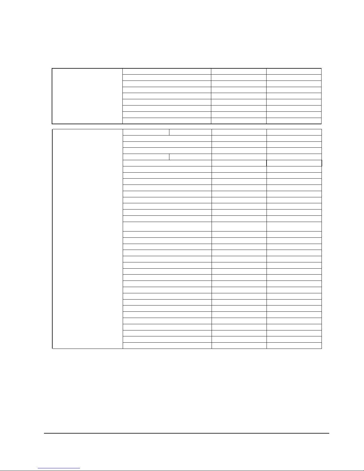
Product Specification
Samsung Electronics 2-3
TIMER RECORDING
12 Events / 1 Month 12 Events / 1 Month
Yes Yes
NO NO
Quartz Quartz
Yes Yes
VideoPlus+ VideoPlus+
-
-
VPS/PDC VPS/PDC
VIDEO
10bit / 54MHz 10bit / 54MHz
Yes Yes
-
-
AUDIO
96kHz / 24bit 96kHz / 24bit
Yes Yes
-
-
-
-
TUNER
Intelligent Auto Set-up Intelligent Auto Set-up
PAL - I PAL - I
VHF / UHF / CATV VHF / UHF / CATV
E21~E69 E21~E69
60CH 60CH
-
A2 / Nicam A2 / Nicam
99 99
YES YES
FEATURES
Yes Yes
-
-
Yes(BLACK) Yes(BLACK)
-
-
-
-
Yes(x128) Yes(x128)
-
-
Yes(10Disc) Yes(10Disc)
Yes(x2,x4) Yes(x2,x4)
1Disc 1Disc
Yes Yes
-
-
Custom Parental Control
Child Door lock for DVD Tray
EZ View
Instant Replay
Bookmark
Zoom
Resume
Layer Indicator
1.5x Audio during Scan Forward
High Speed Scan Search
Instant Advance
Stereo System ( A2 / Nicam )
Station Capacity (Nber of Preset)
Auto Channel Sort & Mapping GŸ Intelligent Auto
Set-up
DVD
Control OSD Menu
Quick Set Up
Start Up Screen
Back Ground Graphic
Screen Saver
Audio/Video Bit Rate Indicator
CH Coverage
RF-out CH & System
Default RF Channel
RF-out channel Auto seeking
Super Audio CD Multi ch Output
Virtual Surround Mode
Tuning System
Broadcast System
Audio DAC
DTS Digital Output
Dolby Digital 5.1ch Decode
DTS 5.1ch Decode
Video DAC
Progressive
Upscaling(720P/1080i)
Custom AV Mode
G-Code/Video+/ShowView
EPG (Gemstar)
Auto speed Timer Recording
VPS or PDC Function
OTR
Backup Time
Clock Type
Auto Clock Set
No. of Events
-
-
-
-
-
-
-
-
-
-
-
-
-
-
-
-
-
-
-
Basic Basic
Samsung Samsung
DVD-VR300E/XEU DVD-VR320/XEU
UK UK
SEUK SEUK
English English
GB/FR/IT/ES/DE/NL GB/FR/IT/ES/DE/NL
SUWON SESK
CE , SEMKO CE , SEMKO
General
GRADE
Brand
MODEL Code
Sales Area
Sales Company
Instruction Manual ( Language )
OSD/OSP - Language
Applied Regulation
Production
Product Specification
2-4 Samsung Electronics
DESIGN
DVD-VR300 DVD-VR320
Silver Silver
LED LED
REMOTE
VR6353-53KEY VR6353-53KEY
AAA AAA
Silver Silver
English English
Yes Yes
Yes Yes
-
Yes (SCART)x1 Yes (SCART)x1
Yes (SCART)x1 Yes (SCART)x1
Yes x1 Yes x1
Yes x1 Yes x1
Yes x1 Yes x1
Yes Yes
Yes(SCART1) Yes(SCART1)
Yes Yes
Yes Yes
Yes Yes
YES NO
-
Yes Yes
NO YES
-
-
-
-
-
-
HDMI Output
USB
PC-Card Slot
Component Video Output
D Terminal (for DVD)
Control-S In
10in2 Memory Slot
S-Video Output(on the Rear)
S-Video Input(on the Front)
S-Video Input(on the Rear)
DV Input (on the Front)
Aerial In / Ant.-Out (on the Rear)
RGB Output 21 Pin
Coaxial Digital Audio Output
Optical Digital Audio Output
Video/Audio In RCA Jack (on the Front)
Video/Audio In RCA Jack (on the Rear)
Video/Audio Out RCA Jack (on the Rear)
Additional Rear Audio Output
Ilumi. Remote
TERMINALS ( IN / OUT )
Video / Audio 21 Pin (on the Rear)
Sat. 21 Pin (on the Rear) with LINE Through (STB
Through)
Language
Gemstar Button / Logo
10key (for Ch Select)
Multi-Brand TV Control
Common
Front Panel
Body Color
Display of Panel Front
Type Name
Battery Type
Color
-
-
-
-
-
-
-
-
-
-
-
Basic Basic
Samsung Samsung
DVD-VR300E/XEU DVD-VR320/XEU
UK UK
SEUK SEUK
English English
GB/FR/IT/ES/DE/NL GB/FR/IT/ES/DE/NL
SUWON SESK
CE , SEMKO CE , SEMKO
General
GRADE
Brand
MODEL Code
Sales Area
Sales Company
Instruction Manual ( Language )
OSD/OSP - Language
Applied Regulation
Production
Product Specification
Samsung Electronics 2-5
ACCESSORIES
UK AP-3 UK AP-3
Yes Yes
Yes Yes
-
Yes Yes
-
-
Yes Yes
Yes Yes
Yes Yes
-
-
-
CARTON BOX
534*190*434 534*190*434
DIMENSION ETC.
430x85x333 430*84*321
5.3 kg 4.8 kg
6.9KG
7.4 kg
45W 45W
220-240V~50 Hz 220-240V~50 Hz
OTHERS
YES YES
-
-
-
-
-
(E-180)SP:3Hr/LP:9Hr (E-180)SP:3Hr/LP:9Hr
SP/LP SP/LP
Yes Yes
YES YES
ENDLESS ENDLESS
Country Origin (Body)
Country Origin (Carton)
NT3.58 PB
VCR COMMON (VHS)
Country Origin (Remote)
POP on the TOP Cover
Copy
Weight ( kg ) <Net>
Weight ( kg ) <Gross>
Power Consumption ON/STANDBY
Power Requirement
HDMI Cable
Bundle Disc
Packing Box (Offset Carton)
Dimension (W*H*D mm) tentative Depth/Height
<Net>
RCA Audio/Video Cable
Instruction Manual
Warranty Card
Customer Inquiry Card
RCA Video Cable
Plug Shap
Remote Controller
Batteries
Euro Scart Cable(21pin)
RF Cable
RCA Audio Cable
Common
COMBO
ONLY
SQPB
NT4.43 PB
Recoding Speed
IPC (VCR)
SECAM PB
MESECAM PB
Auto speed Timer Recording
AUDIO DUBBING
Recoding Time
BACKUP TIME
-
-
-
-
-
-
-
-
-
-
-
-
-
Basic Basic
Samsung Samsung
DVD-VR300E/XEU DVD-VR320/XEU
UK UK
SEUK SEUK
English English
GB/FR/IT/ES/DE/NL GB/FR/IT/ES/DE/NL
SUWON SESK
CE , SEMKO CE , SEMKO
General
GRADE
Brand
MODEL Code
Sales Area
Sales Company
Instruction Manual ( Language )
OSD/OSP - Language
Applied Regulation
Production
Product Specification
2-6 Samsung Electronics
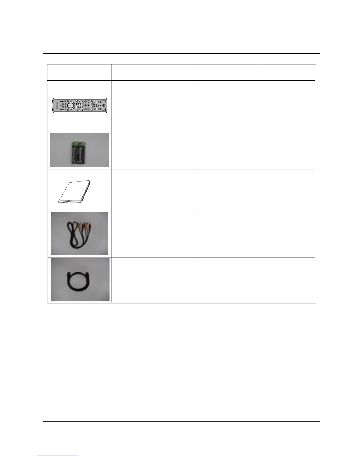
2-3 Option Product Specification
Remote
Control
Batteries for
Remote
Control
Audio & Video
Cable
Owner
s
Instructions
RF Cable
Remark
Parts No
Description
Description Fig
AK59-00034N
AC43-12002H
AC39-22017Z
AC39-42001U
AC39-00017A
S.N.A
AK68-00671B
Model Standard
of DVD-VR320/XEU
Model Standard
of DVD-VR320/XEU
Model Standard
of DVD-VR320/XEU
Model Standard
of DVD-VR320/XEU
Model Standard
of DVD-VR320/XEU
Samsung Electronics 5-1
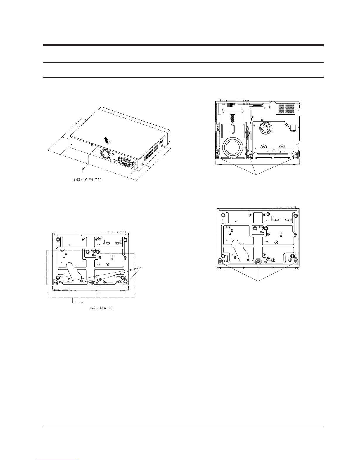
5. Disassembly and Reassembly
5-1 Cabinet and PCB
5-1-1 Cabinet Top Removal
REMOVE 7 SCREWS
Œ
Fig. 5-1 Cabinet Top Removal
5-1-2 Ass’y Bottom Cover Removal
ΠRELEASE 3 HOOKS
´ REMOVE 9 SCREWS
(Bottom View)
Fig. 5-2 Ass’y Bottom Cover Removal
´ RELEASE 3 HOOKS
(Bottom View)
ΠRELEASE 3 HOOKS
(Top View)
Fig. 5-3 Ass’y Front Panel Removal(Top View)
5-1-3 Ass’y Front Panel Removal
Fig. 5-4 Ass’y Front Panel Removal(Bottom View)
5-2
Disassembly and Reassembly
Samsung Electronics
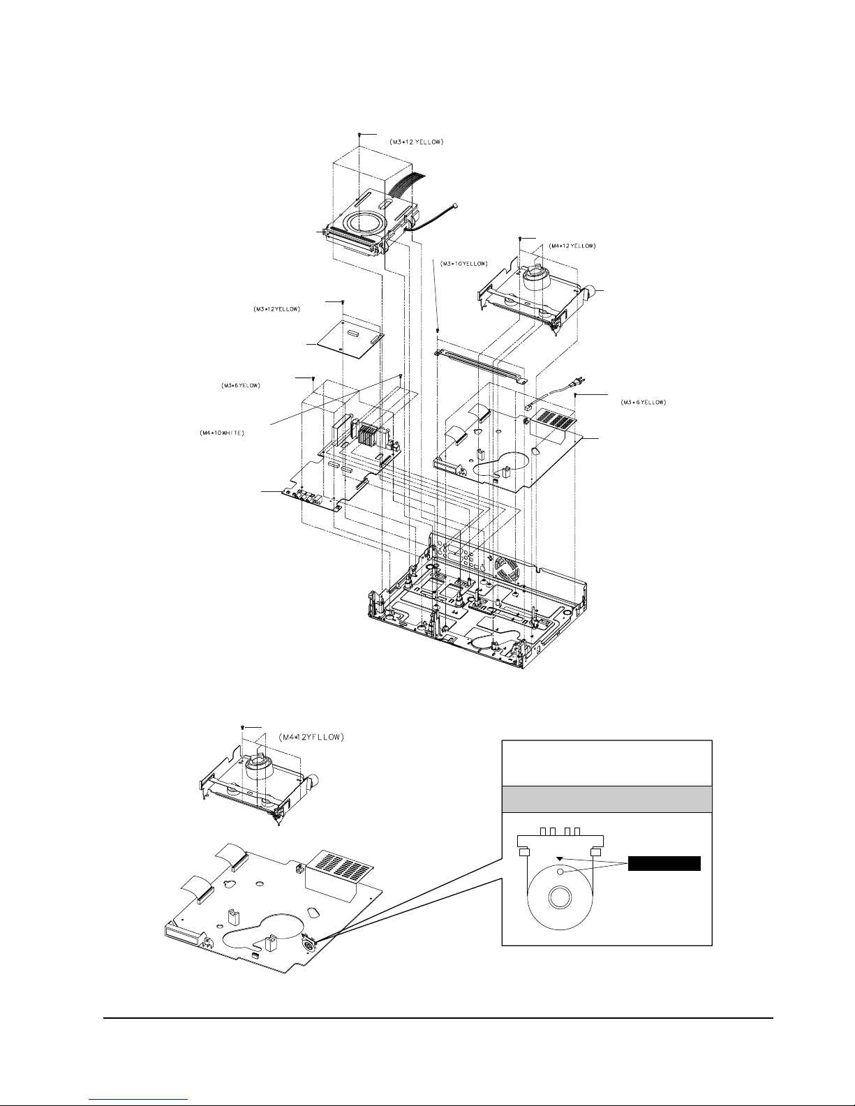
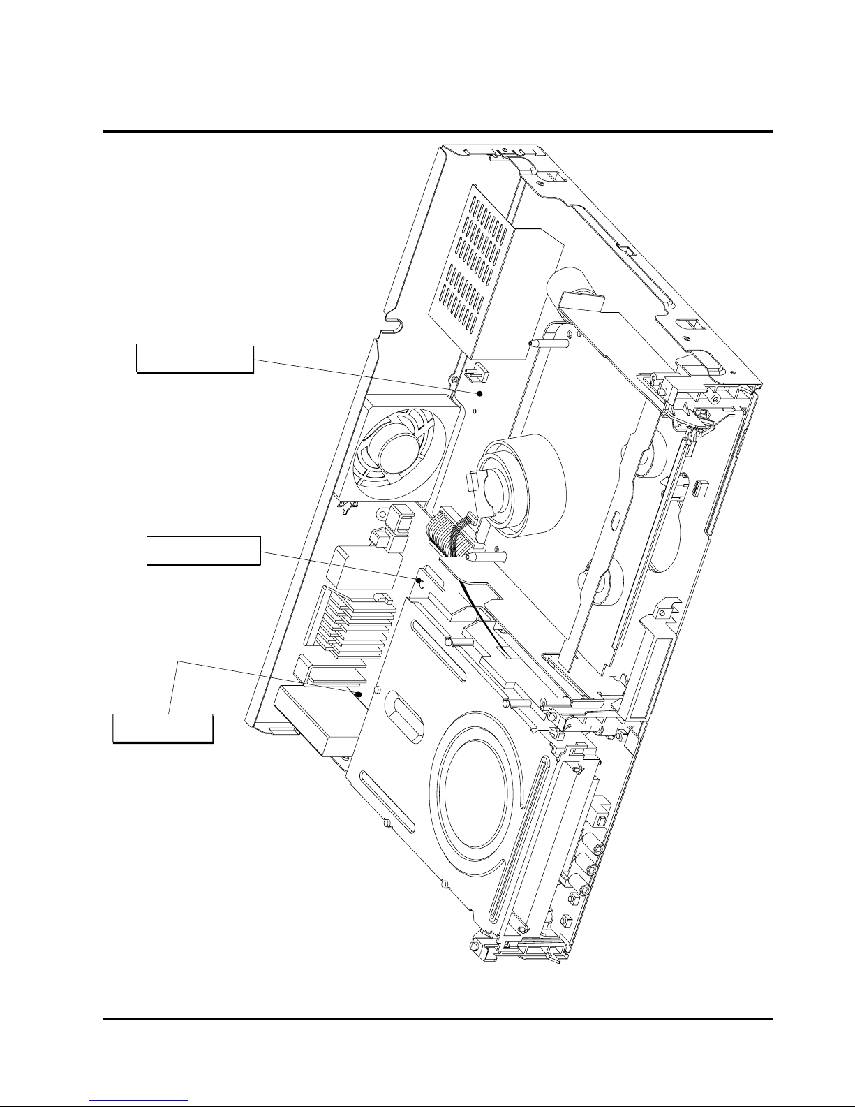
5-1-4 Chassis Removal
VCR MAIN PCB
VCR DECK
DVD DECK
DVD MAIN PCB
JACK PCB
ΠREMOVE 2 SCREWS
´ REMOVE 4 SCREWS
∏ REMOVE 5 SCREWS
ˇ REMOVE 4 SCREWS
¨ REMOVE 2 SCREWS
ˆ REMOVE 5 SCREWS
Ø REMOVE 3 SCREWS
Fig. 5-5 Chassis Removal
5-1-5 VCR Main PCB Removal
ΠREMOVE 4 SCREWS
MODE SWITCH
When installing the ass'y full deck on the Main PCB,
be sure to align the assembly point of mode switch.
ASSEMBLY POINT
Fig. 5-6 VCR Main PCB Removal
Disassembly and Reassembly
5-3Samsung Electronics
5-2 Circuit Board Locations
JACK PCB
VHS MAIN PCB
DVD MAIN PCB
Fig. 5-7 Circuit Board Locations
5-4
Disassembly and Reassembly
Samsung Electronics
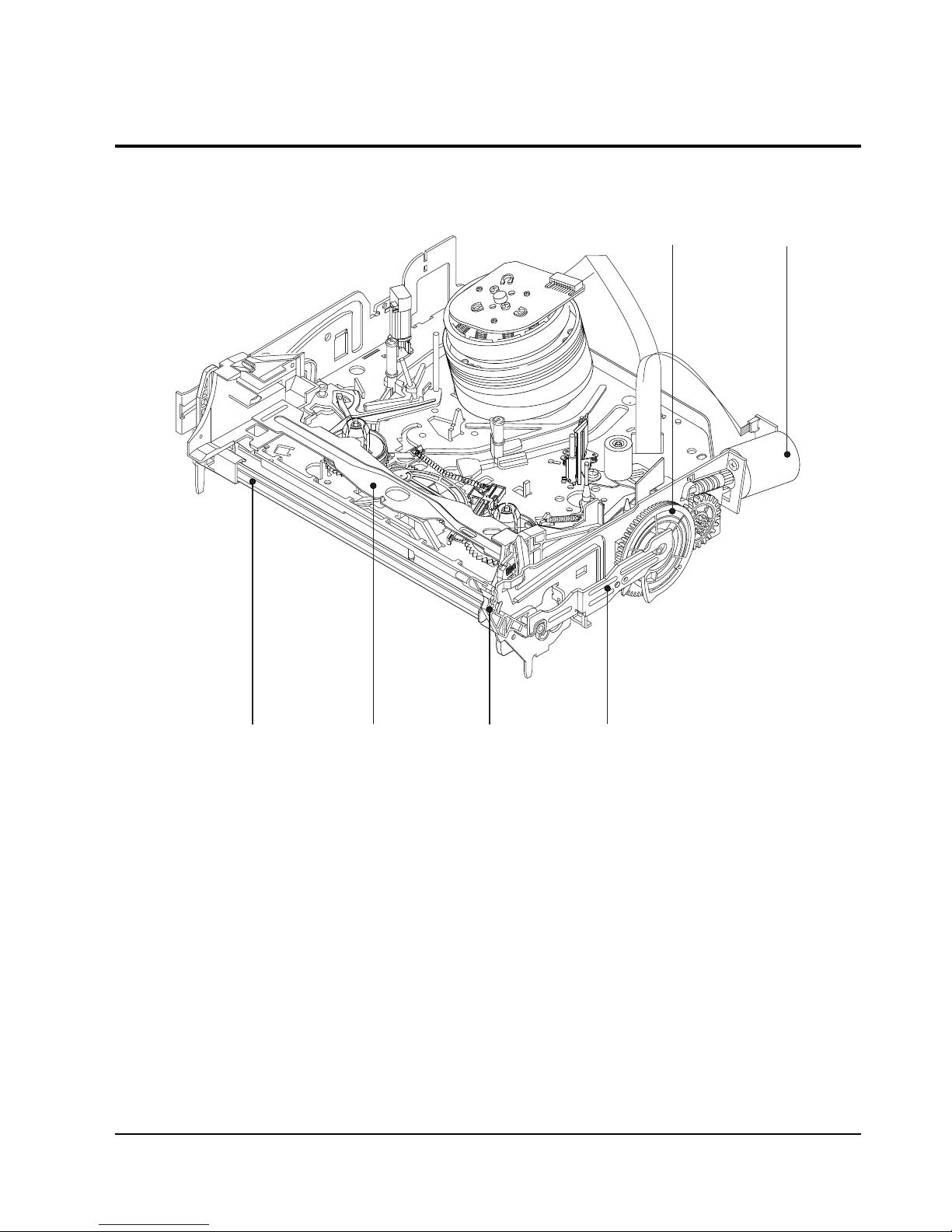
5-3 VCR Deck Parts Locations
5-3-1 Top View
ˆ
Ø
ˇ
¨
Œ
´
Fig. 5-8 Top parts Location-1
ΠGEAR FL CAM
´ MOTOR LOADING ASS’Y
ˇ LEVER FL ARM ASS’Y
¨ HOLDER FL CASSETTE ASS’Y
ˆ LEVER FL DOOR
Ø SLIDER FL DRIVE
Disassembly and Reassembly
5-5Samsung Electronics
Œ
´
Ø
∏”’ Ô˝
Ò
˝
ˇ¨
ˆ
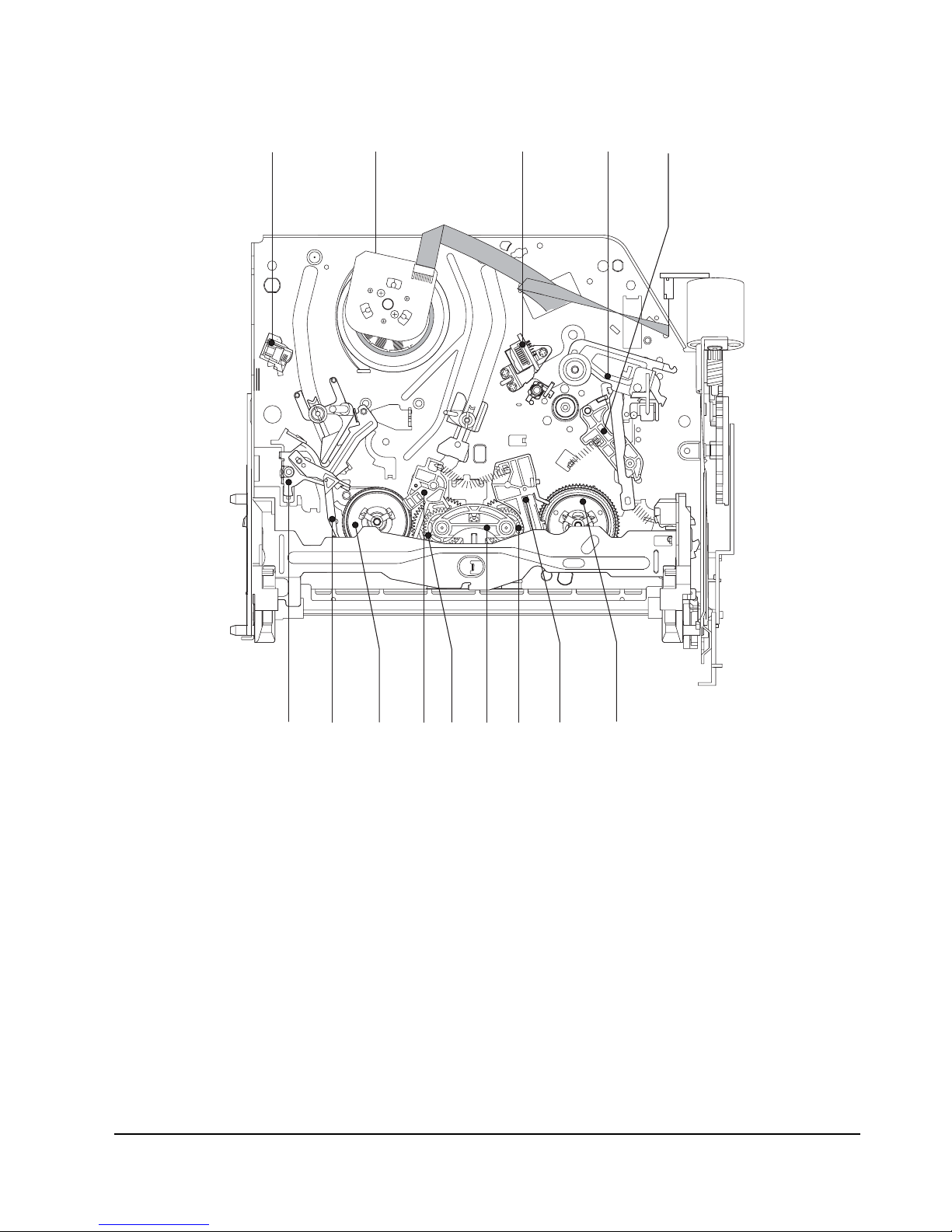
Fig. 5-9 Top Parts Location-2
ΠFE HEAD
´ CYLINDER ASS’Y
ˇ ACE HEAD ASS’Y
¨ LEVER UNIT PINCH ASS’Y
ˆ LEVER #9 GUIDE ASS’Y
Ø LEVER TENSION ASS’Y
∏ BAND BRAKE ASS’Y
” DISK S REEL
’ LEVER S BRAKE ASS’Y
˝ GEAR IDLE
Ô LEVER IDLE
LEVER T BRAKE ASS’Y
Ò DISK T REEL

5-6
Disassembly and Reassembly
Samsung Electronics
5-3-2 Bottom View
Œ
´ˇ
¨
ˆ
Ø
∏
”
’
˝
Fig. 5-10 Bottom Parts Location
ΠGEAR JOINT 1
´ GEAR JOINT 2
ˇ BRAKET GEAR
¨ MOTOR CAPSTAN ASS’Y
ˆ LEVER T LOAD ASS’Y
Ø GEAR LOADING DRIVE
∏ LEVER S LOAD ASS’Y
” HOLDER CLUTCH ASS’Y
’ BELT PULLEY
˝ SLIDER CAM
Disassembly and Reassembly
5-7Samsung Electronics
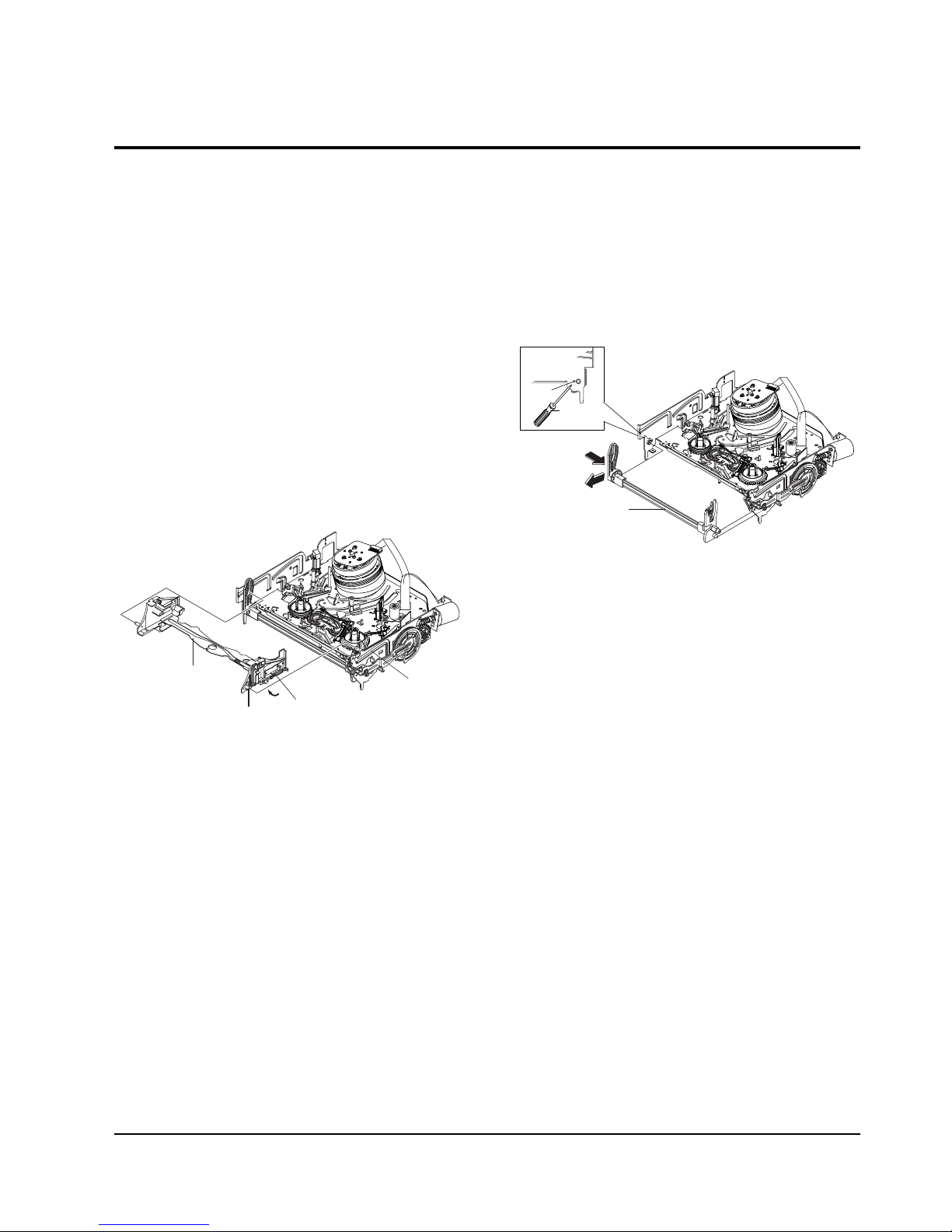
5-4 VCR Deck
PIN
HOLE "A"
ΠLEVER FL ARM ASS'Y
"C"
"B"
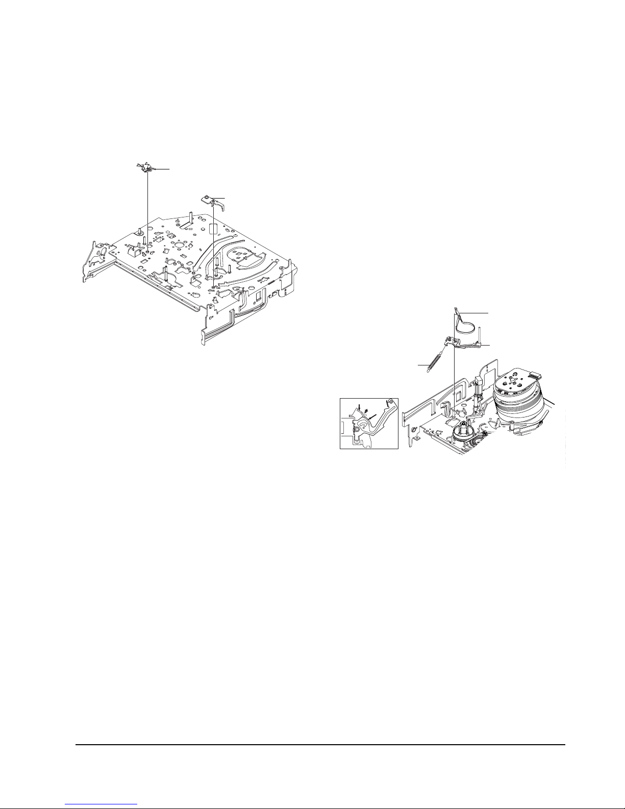
5-4-1 Holder FL Cassette Ass’y Removal
1) Pull the Holder FL Cassette Ass'y Πto the eject
position.
2) Pull the Holder FL Cassette Ass'y Πas grasping
the Holder FL Cassette Ass'y Πand Lever FL
Cassette-R ´ in the same time to release hooking
from Main Base until the Boss [A] of Holder FL
Cassette Ass'y Πis taken out from the Rail [B].
3) Lift the Holder FL Cassette Ass'y Œ, in this time,
you have to grasp the Lever FL Cassette-R ´
Continuously until the Holder FL Cassette Ass'y
Πis taken out completely.
Note : Be sure to insert Lever FL Cassette-R ´ in the
direction of “A” to prevent separation and breakage
of the Lever FL Cassette-R ´ at disassembling and
reassembling.
RAIL [B]
BOSS [A]
´ LEVER FL CASSETTEE -R
"A"
ΠHOLDER FL
CASSETTEE ASS'Y
Fig. 5-11 Holder FL Cassette Ass’y Removal
5-4-2 Lever FL Arm Ass’y Removal
1) Push the hole “A” in the direction of arrow “B”
use the pin.(about Dia. 2.5)
2) Pull out the Lever FL Arm Ass'y Πfrom the Boss
of Main Base.
3) Remove the Lever FL Arm Ass'y Πin the direction
of arrow “C”.
Fig. 5-12 Lever FL Arm Ass’y Removal
5-8
Disassembly and Reassembly
Samsung Electronics
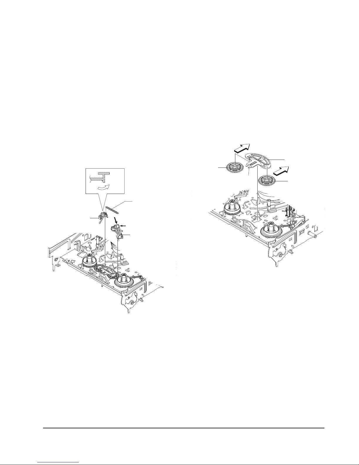
ΠGEAR FL CAM
GEAR WORM WHEEL
POST
TIMING POINT
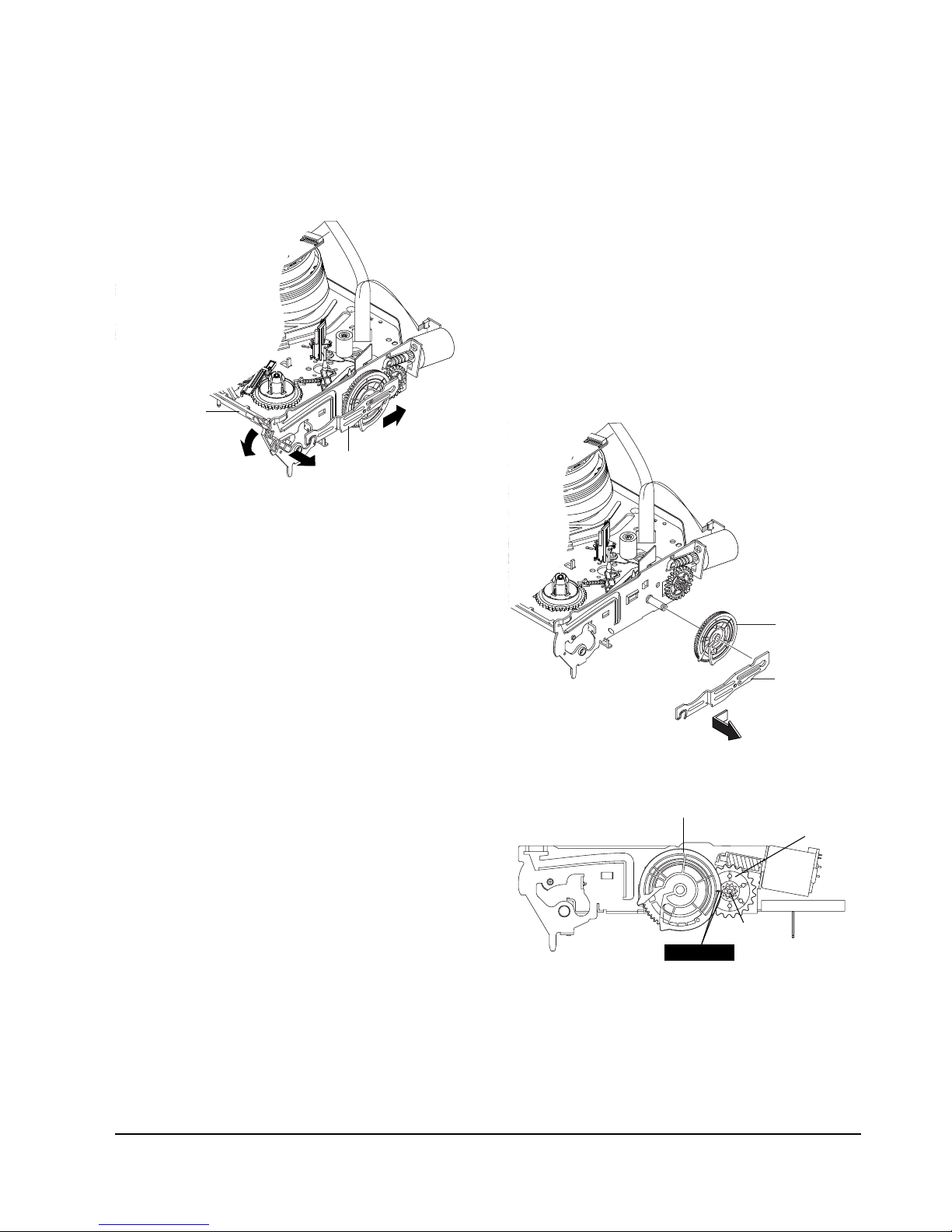
Fig. 5-15 Gear FL Cam, Gear Worm
5-4-4 Slider FL Drive, Gear FL Cam Removal
1) Pull the Slider FL Drive Πto the front direction.
2) Remove the Slider FL Drive Πin the direction of
arrow. (Refer to Fig. 5-13)
3) Remove the Gear FL cam ´.
Note : When reinstalling be sure to reassemble Slider
FL drive Πafter you insert the Boss of Lever FL
ARM-R in Groove of Slider Fl drive Œ.
Assembly : Align the Gear FL Cam Πwith the Gear
worm wheel Post as shown drawing.
(Refer to Timing point)
ΠSLIDER FL DRIVE
´ GEAR FL CAM
Fig. 5-14 Slider FL Drive Removal
5-4-3 Lever FL Door Removal
1) Release the Hook ´ and Remove the Lever FL
Door Œ in the direction of arrow “A”.
Fig. 5-13 Lever FL Door Removal
"B"
"C"
"A"
´ LEVER FL DOOR
ΠSLIDER FL DRIVE
Disassembly and Reassembly
5-9Samsung Electronics
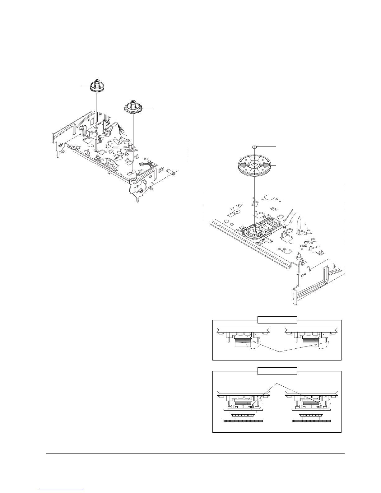
5-4-5 Gear Worm Wheel Removal
1) Remove the Gear Worm wheel Œ.
ΠGEAR WORM WHEEL
Fig. 5-16 Gear Worm Wheel Removal
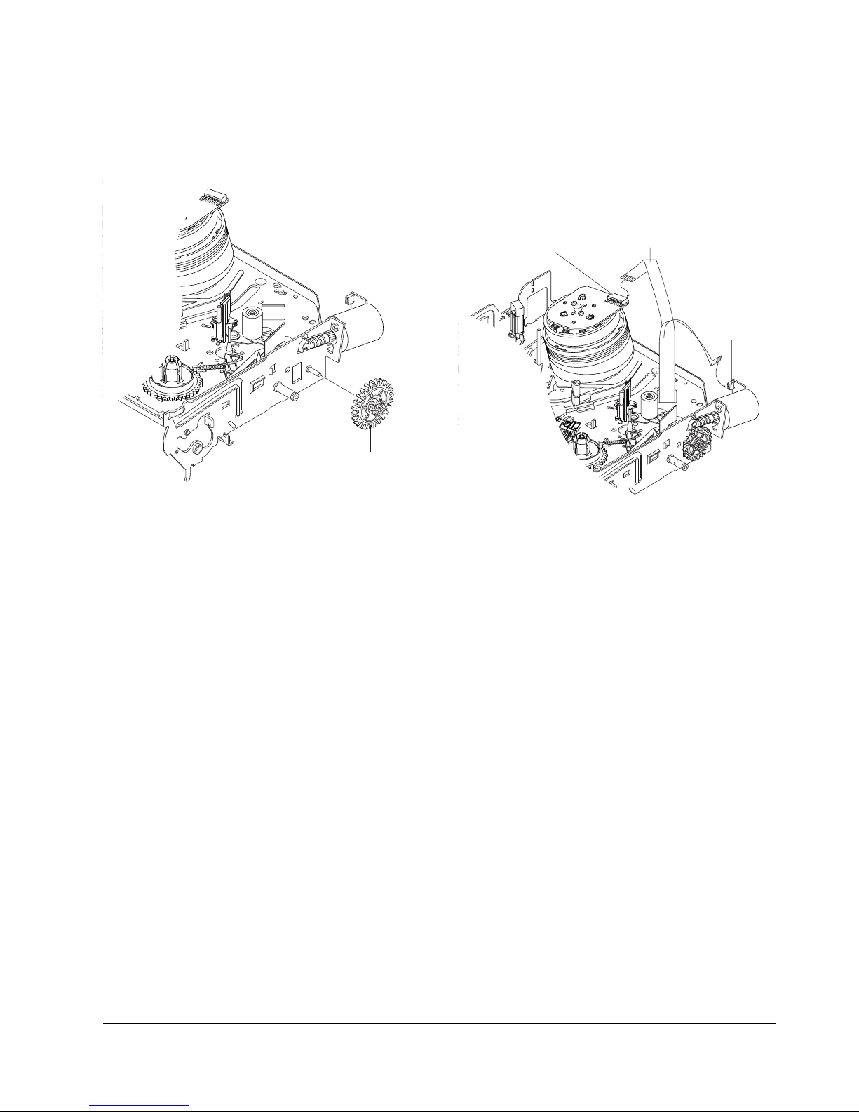
5-4-6 Cable Flat Removal
1) Remove the Drum connecting part of Cable Flat Œ
from Connector Waffer ´.
2) Remove the Loading Motor connecting part of
Cable Flat Œ from Connector Waffer ˇ.
ˇ CONNECTOR
WAFER
´ CONNECTOR WAFER
ΠCABLE FLAT
Fig. 5-17 Cable Flat Removal
5-10
Disassembly and Reassembly
Samsung Electronics
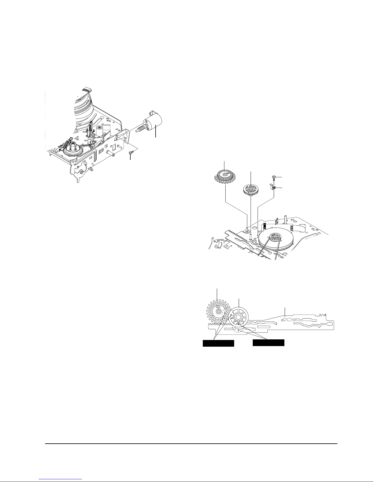
5-4-8 Bracket Gear, Gear Joint 2, 1 Removal
1) Remove the SCREW Œ.
2) Remove the Bracket Gear ´.
3) Remove the Gear Joint 2 ˇ.
4) Remove the Gear Joint 1 ¨.
Assembly :
1) Be sure to align dot mark of Gear Joint 1 Œwith
dot mark of Gear Joint 2 ´ as shown Fig 5-20.
(Refer to Timing point1)
2) Confirm the Timing Point 2 of the Gear Joint 2 ´
and Slider Cam ˇ.
ΠSCREW
´ BRAKET GEAR
¨ GEAR JOINT 1
ˇ GEAR JOINT 2
Fig. 5-19 Bracket Gear, Gear Joint 1,2 Removal
ΠGEAR JOINT1
´ GEAR JOINT2
ˇ SLIDER CAM
TIMING POINT 1
TIMING POINT 2
Fig. 5-20 Gear Joint 1,2 Assembly
5-4-7 Motor Loading Ass’y Removal
1) Remove the screw Œ.
2) Remove the Motor Loading Ass’y ´.
´ MOTOR LOADING ASS`Y
ΠSCREW
Fig. 5-18 Motor Loading Ass’y Removal
Disassembly and Reassembly
5-11Samsung Electronics
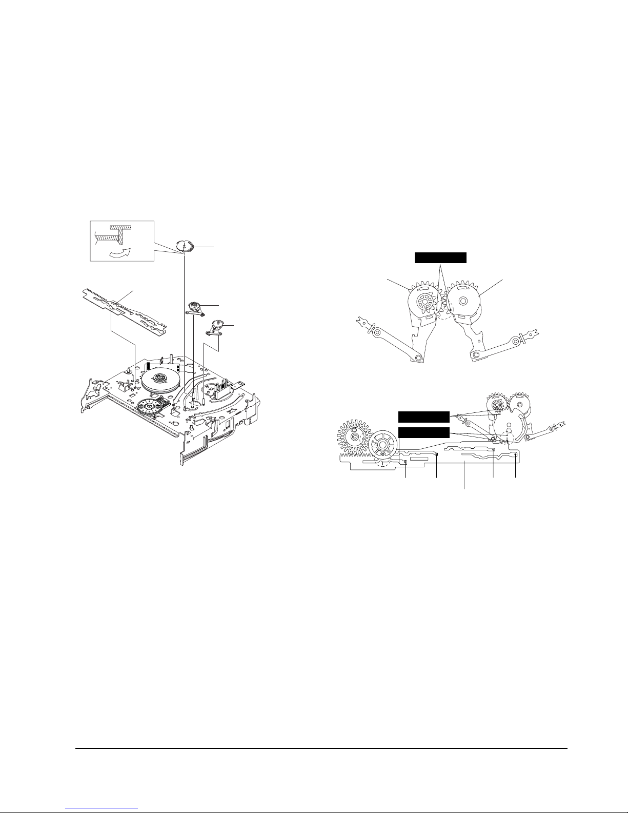
5-4-10 Gear Loading Drive, Slider Cam,
Lever Load S, T Ass’y Assembly
1) When reinstalling, be sure to align dot of Lever
Load T Ass'y Œwith dot of Lever Load S Ass'y ´
as shown in drawing, (Refer to Timing Point 1).
2) Insert the Pin A,B,C,D into the Slider Cam ˇhole,
3) Be sure to align dot of Lever Load T Πand dot of
Gear Loading Drive ¨, (Refer to Timing Point 2).
4) Aline dot of Gear Loading drive ¨ with mark of
Slider Cam ˇ as shown in drawing(Refer to
Timing Point 3).
´ LEVER LOAD S
Œ
LEVER LOAD T
PIN A
PIN C
PIN B
PIN D
ˇ SLIDER CAM
TIMING POINT 2
TIMING POINT 1
TIMING POINT 3
Fig. 5-22 Gear Loading Drive, Slider Cam,
Lever Load S, T Ass’y Assembly
5-4-9 Gear Loading Drive, Slider Cam,
Lever Load S, T Ass’y Removal
1) Remove the Belt Pulley. (Refer to Fig. 5-38)
2) Remove the Gear Loading Drive Πafter releasing
Hook [A] in the direction arrow as shown in detail
drawing.
3) Remove the Slider Cam ´.
4) Remove the Lever Load S Ass’y ˇ & Lever Load T
Ass’y ¨.
HOOK(A)
ΠGEAR LOADING DRIVE
ˇ LEVER LOAD S ASS'Y
¨ LEVER LOAD T ASS'Y
´ SLIDE CAM
Fig. 5-21 Gear Loading Drive, Slider Cam,
Lever T, S Load Ass’y Removal
5-12
Disassembly and Reassembly
Samsung Electronics
5-4-12 Lever Tension Ass’y,
Band Brake Ass’y Removal
1) Remove the Lever Brake S Ass'y (Refer to Fig 5-25).
2) Remove the Spring Tension Lever Œ.
3) Rotate stopper of Main Base in the direction of
arrow “A”.
4) Lift the Lever Tension Ass'y ´ & Band brake
Ass'y ˇ.
Note :
1) When replacing the Lever Tension Ass'y ´, be sure
to apply Grease on the post,
2) Take care not to touch stain on the felt side, and not
to be folder and broken Band brake Ass'y
3) After Lever Tension Ass'y seated, Rotate stopper of
Main Base to the Mark[B].
STOPPER
MARK[B]
"A"
ΠSPRING TENTION LEVER
´ LEVER TENTION ASS`Y
ˇ BAND BRAKE ASS`Y
Fig. 5-24 Lever Tension Ass’y,
Band Brake Ass’y Removal
5-4-11 Lever Pinch Drive,
Lever Tension Drive Removal
1) Remove the Lever Pinch Drive Œ, Lever Tension
Drive ´.
ΠLEVER PINCH DRIVE
´ LEVER TENSION DRIVE
Fig. 5-23 Lever Pinch Drive,
Lever Tension Drive Removal
Disassembly and Reassembly
5-13Samsung Electronics
5-4-14 Gear Idle Ass’y Removal
1) Push the Lever Idle Πin the direction of arrow
“A”, “B”.
2) Lift the Lever Idle Œ.
Assembly :
1) Apply oil in two Bosses of Lever Idle Œ.
2) Assemble the Gear Idle ´ with the Lever Idle Œ.
Note : When replacing the Gear Idle ´, be sure to
add oil in the boss of Lever Idle Œ.
´ GEAR IDLE
´ GEAR IDLE
ΠLEVER IDLE
"A"
HOOK "C"
"B"
Fig. 5-26 Gear Idle Ass’y Removal
5-4
-13 Lever Brake S, T Ass’y
Removal
1) Release the Hook [A] and the Hook [B], [C] in the
direction of arrow as shown in Fig 5-25.
2) Lift the Lever S, T Brake Ass'y Œ, ´ with spring
brake ˇ.
Assembly :
1)Assembly the Lever S Brake Ass'y Πon the Main
Base.
2)Assembly the Lever T Brake Ass'y ´ with spring
brake ˇ.
Note : Take extreme care not to be folded and
transformed Spring Brake at removing or reinstalling.
HOOK(A)
ΠLEVER S BRAKE ASS'Y
´ LEVER T BRAKE ASS`Y
ˇ SPRING BRAKE
HOOK(B)
HOOK(C)
Fig. 5-25 Lever Brake S, T Ass’y Removal
5-14
Disassembly and Reassembly
Samsung Electronics
5-4-16 Holder Clutch Ass’y Removal
1) Remove the Washer Slit Œ.
2) Lift the Holder Clutch Ass’y ´.
Note : When you reinstall Holder Clutch Ass'y
1) Check the condition of spring as shown in detail A.
2) Don't push Holder Clutch Ass'y down with excessive force Just insert Holder Clutch Ass'y into post
center with dead force and Rotate it smoothly.
Be sure to confirm that spring is in the slit of Gear
Center Ass'y as shown in detail B.
ΠDISK S REEL
´ DISK T REEL
ΠWASHER SLIT
´ HOLDER CLUTCH ASS`Y
DETAIL A
<BAD> SPRING <GOOD>
<BAD>
SPRING
<GOOD>
DETAIL B
Fig. 5-27 Disk S, T Reel Removal
Fig. 5-28 Holder Clutch Ass’y Removal
5-4-15 Disk S, T Reel Removal
1) Lift the Disk S, T Reel Œ, ´.
Disassembly and Reassembly
5-15Samsung Electronics
ΠGUIDE CASSETTE DOOR
HOOK [A]
Fig. 5-31 Guide Cassette Door Removal
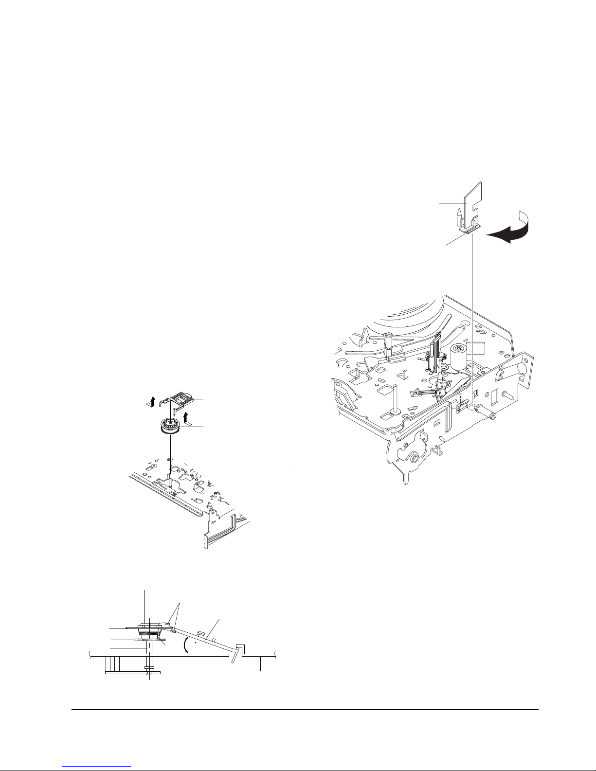
4-4-18 Guide Cassette Door Removal
1) Lift the Hook [A].
2) Rotate the Guide Cassette Door Πin the direction
of arrow.
Note : After reinstalling the Guide Cassette Door Œ
sure the Hook [A].
5-4-17 Lever Up Down Ass’y, Gear Center
Ass’y Removal
1)
Remove the 2 hooks in the direction of arrow as
shown Fig. 5-28 and lift the Lever Up Down Ass’y
Œ.
2) Lift the Gear Center Ass’y ´.
Assembly :
1) Insert the Lever Up Down Ass'y Πin the rectan-
gular holes on Main Base as shown in Fig 5-30.
2) Lift the Lever Up Down Ass'y Œ about 35°.
(Refer to Fig 5-30)
3) Insert Ring of the Gear Center Ass'y ´ in the
Guide of the Lever Up Down Ass'y Œ.
4) Insert the Gear Center Ass'y ´ in the post on
Main Base.
5) Push down the Lever Up Down Ass'y Πfor
locking of the Hook.
Note :
1) Take care not to separate and sentence does not
mark sense.
2) Be sure to confirm that Ring of the Gear Center
Ass'y ´ is in the Guide of the Lever Up Down
Ass'y Πafter finishing assembly of Lever Up
Down Ass'y Œ and Gear Center Ass'y ´.
ΠLEVER UP DOWN ASS`Y
´ GEAR CENTER ASS`Y
MAIN BASE
LEVER UP DOWN ASS'Y
GUIDE
GEAR CENTER ASS'Y
RING
GEAR
POST
HOOK
35
Fig. 5-29 Lever Up Down Ass’y Removal
Fig. 5-30 Lever Up Down Ass’y Removal
5-16
Disassembly and Reassembly
Samsung Electronics
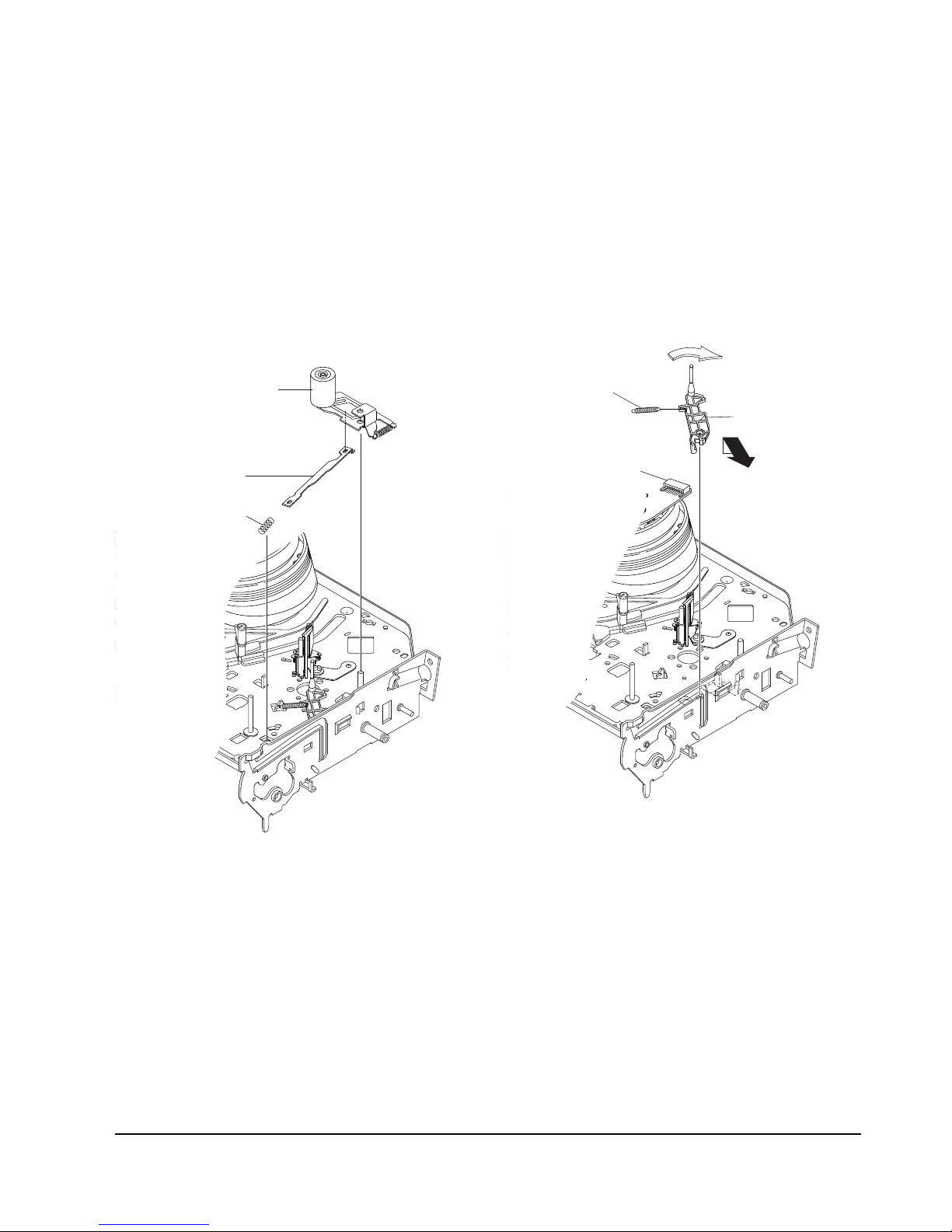
5-4-19 Lever Unit Pinch Ass’y, Plate Joint,
Spring Pinch Drive Removal
1) Lift the Unit Pinch Ass’y Œ.
2) Remove the Plate Joint ´ from Lever Pinch Drive.
3) Remove the Spring Pinch Drive ˇ.
Note :
1) Take extreme care not to touch the grease on the
Roller Pinch.
2) When reinstalling, be sure to apply grease on the
post pinch roller.
ˇ SPRING PINCH DRIVE
ΠLEVER UNIT PINCH ASS`Y
´ PLATE JOINT
Fig. 5-32 Lever Unit Pinch Ass’y, Plate Joint,
Spring Pinch Drive Removal
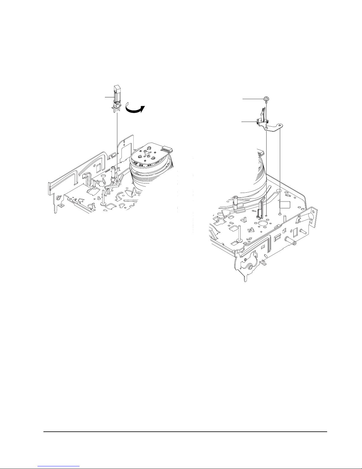
5-4-20 Lever #9 Guide Ass’y Removal
1) Remove the Spring #9 Guide Œ.
2) Lift the Spring #9 Guide Ass’y ´ in the direction
of arrow “A”.
Note :
1) Take extreme care not to get grease on the tape
Guide Post.
2) After reinstalling, check the bottom side of the Post
#9 Guide to the top side of Main Base.
ΠSPRING #9 GUIDE
A
´ LEVER #9 GUIDE ASS`Y
"B"
Fig. 5-33 Lever #9 Guide Ass’y Removal
Disassembly and Reassembly
5-17Samsung Electronics
5-4-22 ACE Head Removal
1) Pull out the FPC from connector of ACE Head
Ass’y ´.
2) Remove the screw Œ.
3) Lift the ACE Head Ass’y ´.
ΠSCREW
´ HEAD ACE ASS`Y
Fig. 5-35 ACE Head Removal
5-4-21 FE Head Removal
1) Remove the screw Œ.
2) Lift the FE Head ´.
ΠFE HEAD
Fig. 5-34 FE Head Removal
5-18
Disassembly and Reassembly
Samsung Electronics
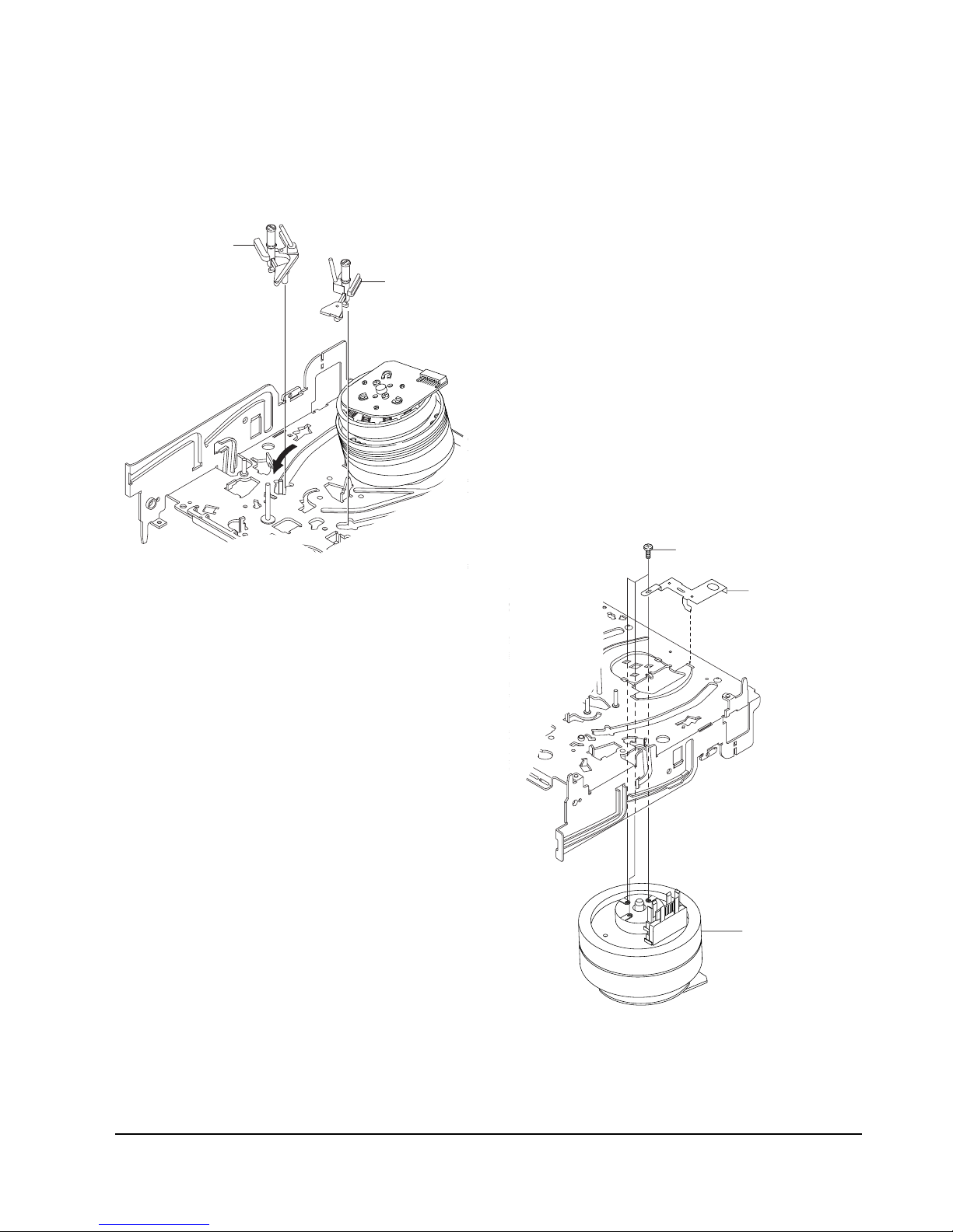
5-4-23 Slider S, T Ass’y Removal
1) Move the Slider S, T Ass’y Œ, ´ to slot, and then
lift it to remove. (Refer to arrow)
ΠSLIDER S ASS`Y
´ SLIDER T ASS`Y
Fig. 5-36 Slider S, T Ass’y Removal
5-4-24
Plate Ground Deck, Cylinder Ass’y Removal
1) Remove the 3 Screws Œ.
2) Lift the Plate Ground Deck ´.
3) Lift the Cylinder Ass’y ˇ.
Assembly :
1) Match the 3 holes in the bottom of Cylinder ass'y
ˇ to the 3 holes of Main Base as attending not to
drop or knock the Cylinder ass'y ˇ.
2) Tighten the 1 Screw Œ.
3) Match the Plate Ground Deck ´ to the Hole of
Base Main.
4) Tighten the other 2 Screws Œ.
Note :
1) Take care not to touch the Cylinder Ass'y ˇ and
the tape guide post at reinstalling.
2) When reinstalling, Don't push down too much on
Screw Driver.
Π3 SCREWS
´ PLATE GROUND DECK
ˇ CYLINDER ASS'Y
Fig. 5-37 Plate Ground Deck, Cylinder Ass’y Removal
Disassembly and Reassembly
5-19Samsung Electronics
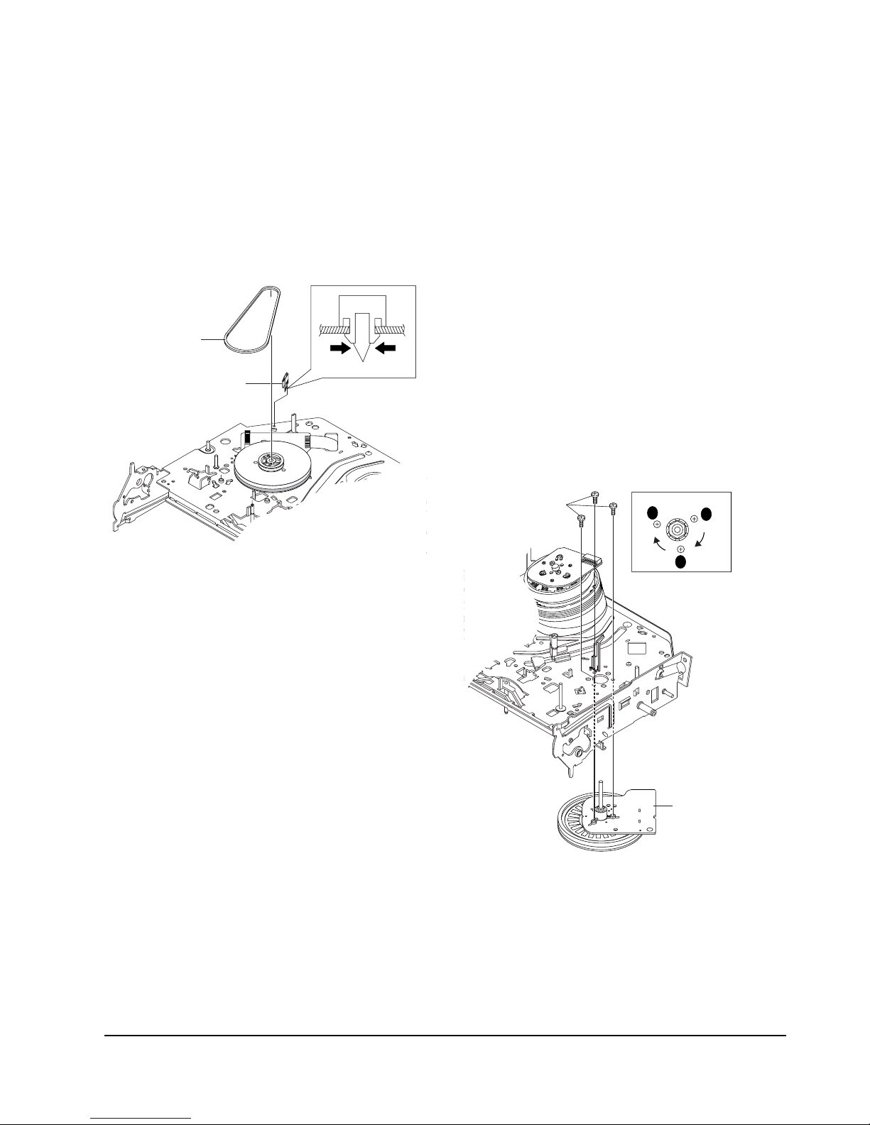
5-4-26 Motor Capstan Ass’y Removal
1) Remove the Damper Capstan Πin the direction
of arrow.
2) Remove the 3 Screws ´.
3) Remove the Motor Capstan Ass’y ˇ.
Assembly :
1) Match the 3 holes of Motor Capstan Ass’y ˇ to the
3 holes of Main Base. Be careful not to drop or
knock the Motor Capstan Ass'y ˇ.
2) Tighten the 3 Screws ´ in the direction of arrow
as shown detail drawing.
3) Assemble the Damper Capstan Œ.
Note : After tightening screws, check if there is gap
between the head of screws and the top side of Main
Base. There should have no gap between the head of
screws and the top side of Main Base.
After reinstalling, adjusting the tape transport
system again.
A
B
C
´ MOTOR CAPSTAN ASS'Y
Π3 SCREWS
Fig. 5-39 Motor Capstan Ass’y Removal
5-4-25 Hook Capstan, Belt Pulley Removal
1) Remove the Hook Capstan Πafter realeasing
Hook in the direction arrow as shown in detail
drawing.
2) Remove the Belt Pulley ´.
Note : Take extreme care not to get grease on Belt
Pulley ´ at assembling or reassembling.
´ BELT PULLEY
ΠHOOK CAPSTAN
HOOK
Fig. 5-38 Hook Capstan, Belt Pulley Removal
5-20
Disassembly and Reassembly
Samsung Electronics
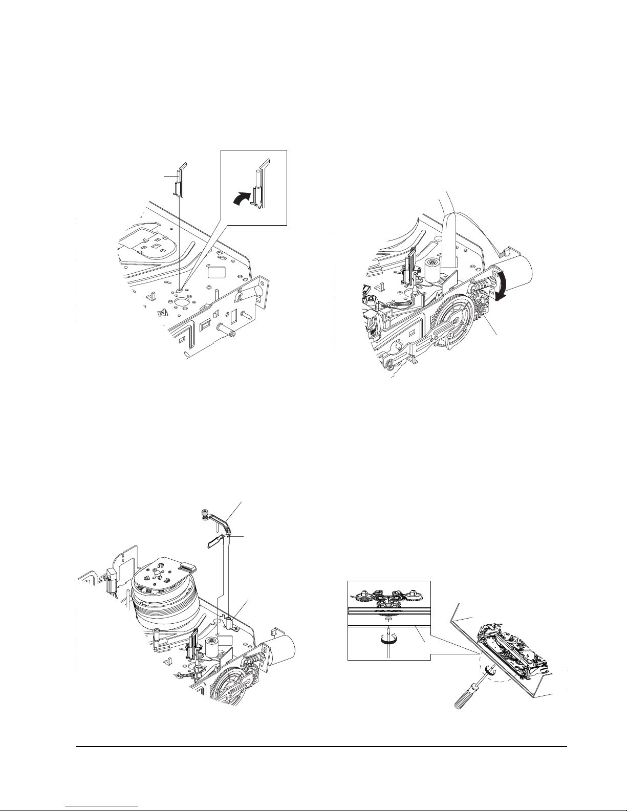
5-4-29 How to Eject the Cassette Tape
(If the unit does not operate on condition that is
inserted into housing ass’y)
1) Turn the Gear worm Πclockwise with screw
driver.(Refer to arrow)
(Other method : Remove the Screw of Motor Load
Ass'y, Separate the Motor Load Ass'y)
ΠGEAR WORM
Fig. 5-42
Fig. 5-43
2) When Slider S,T are approched in the position of
unloading, rotate holder Clutch counterclockwise
after inserting screw driver in the hole of frame's
bottom in order to wind the unwinded tape.
(Refer to Fig.5-43)
(If you rotate Gear Worm Πcontinuously when
tape is in state of unwinding, you may cause a
tape contamination by grease and tape damage.
Be sure to wind the unwinded tape in the state of
set horizently.)
3) Rotate Gear Worm Πclockwise using screw driver
again up to the state of eject mode and then pick
out the tape.(Refer to Fig.5-42)
FRAME
5-4-27 Post #8 Guide Ass’y Removal
1) Rotate the Post #8 Guide Ass’y Œ in the direction
of arrow to lift up.
ΠPOST #8 GUIDE ASS'Y
Fig. 5-40 Post #8 Guide Ass’y Removal
5-4-28 Level Head Cleaner Ass’y Removal
(Optional)
1) Release the Hook Œ.
2) Lift the Lever Head Cleaner Ass’y
´.
ΠHOOK
´ LEVER HEAD CLEANER ASS'Y
SLEEVE-HEAD CLEANER
Fig. 5-41 Lever Head Cleaner Ass’y Removal
 Loading...