

Samsung DVD-P350K/XEV, DVD-P350K/XSE, DVD-P350K/XTL, DVD-P350K/XTC, DVD-P350K/XSS Service Manual
...
DVD PLAYER
Chassis : Spino
DVD-P350K/XEV, XSE, XTC, XTL, CDM,
XSS, SMR, XST, XSV, XSH,
TWN, XSA, RAD, SAM, TAW,
UMG, ELT, XSG, XFA, AFR,
FES, AND
DVD-P355K/XEV, XAX, XAP, XAO, STR,
RCL, GEN, XAZ, XBG, CHN
DVD-P355/XEV, XAX, XAP, XAO, STR,
RCL, GEN, XAZ, XBG, XEU,
XET, XEE, SED, XEO, XEC,
XEL, FOU, XEG, XEH, FES,
AFR, XSE
DVD-P67000MK
SERVICE
ŒŒ
41mm With LED Module
´´
Playback MPEG4 DVD-Audio
(DVD-P355K/P355 Only)
ˇˇ
ZORAN Vaddis7 1-Chip Solution
¨¨
Karaoke Model
(DVD-P350K/P355K/P67000MK Only)
Manual
DVD PLAYER
Merit & Character regarding Product
SERVICE MANUAL
DVD-P350K/P355K/P355/P67000MK
DVD-P350K/P67000MK
DVD-P355K
DVD-P355
ELECTRONICS
© Samsung Electronics Co., Ltd. MAR . 2005
Printed in Korea
AK82-00723A
This Service Manual is a property of Samsung Electronics Co.,Ltd.
Any unauthorized use of Manual can be punished under applicable
international and/or domestic law.
Samsung Electronics 1-1
1. Precautions
1-1 Safety Precautions
1) Before returning an instrument to the customer,
always make a safety check of the entire instrument,
including, but not limited to, the following items:
(1) Be sure that no built-in protective devices are
defective or have been defeated during servicing.
(1)Protective shields are provided to protect both
the technician and the customer. Correctly replace
all missing protective shields, including any
removed for servicing convenience.
(2)When reinstalling the chassis and/or other assembly in the cabinet, be sure to put back in place
all protective devices, including, but not limited to,
nonmetallic control knobs, insulating fish papers,
adjustment and compartment covers/shields, and
isolation resistor/capacitor networks. Do not operate this instrument or permit it to be operated without all protective devices correctly installed and
functioning.
(2) Be sure that there are no cabinet openings through
which adults or children might be able to insert
their fingers and contact a hazardous voltage. Such
openings include, but are not limited to, excessively wide cabinet ventilation slots, and an improperly fitted and/or incorrectly secured cabinet back
cover.
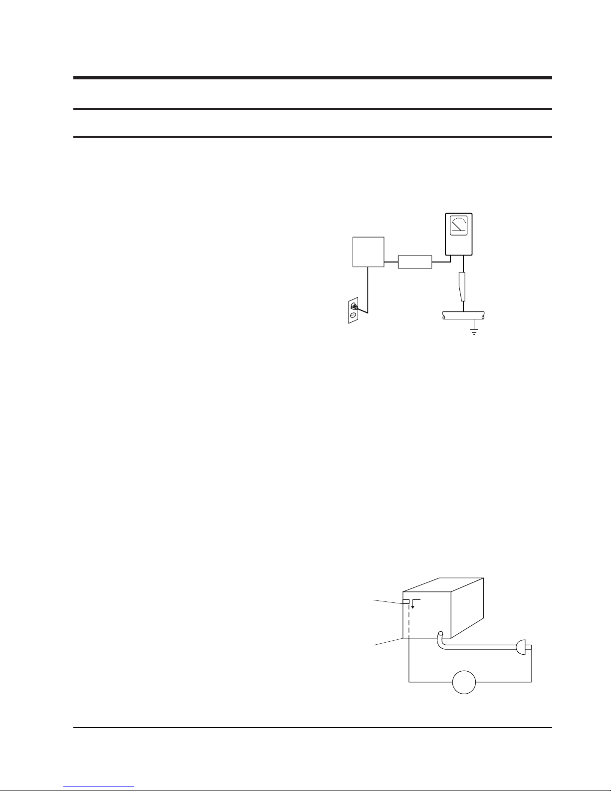
(3) Leakage Current Hot Check-With the instrument
completely reassembled, plug the AC line cord
directly into a 120V AC outlet. (Do not use an isolation transformer during this test.) Use a leakage
current tester or a metering system that complies
with American National Standards institute (ANSI)
C101.1 Leakage Current for Appliances and
Underwriters Laboratories (UL) 1270 (40.7). With
the instrument’s AC switch first in the ON position
and then in the OFF position, measure from a
known earth ground (metal water pipe, conduit,
etc.) to all exposed metal parts of the instrument
(antennas, handle brackets, metal cabinets, screwheads, metallic overlays, control shafts, etc.), especially any exposed metal parts that offer an electrical return path to the chassis.
Any current measured must not exceed 0.5mA.
Reverse the instrument power cord plug in the outlet and repeat the test. See Fig. 1-1.
Any measurements not within the limits specified
herein indicate a potential shock hazard that must
be eliminated before returning the instrument to
the customer.
Fig. 1-1 AC Leakage Test
(4) Insulation Resistance Test Cold Check-(1) Unplug
the power supply cord and connect a jumper wire
between the two prongs of the plug. (2) Turn on the
power switch of the instrument. (3) Measure the
resistance with an ohmmeter between the
jumpered AC plug and all exposed metallic cabinet
parts on the instrument, such as screwheads,
antenna, control shafts, handle brackets, etc. When
an exposed metallic part has a return path to the
chassis, the reading should be between 1 and 5.2
megohm. When there is no return path to the chassis, the reading must be infinite. If the reading is
not within the limits specified, there is the possibility of a shock hazard, and the instrument must be
repaired and rechecked before it is returned to the
customer. See Fig. 1-2.
Fig. 1-2 Insulation Resistance Test
DEVICE
UNDER
TEST
(READING SHOULD
NOT BE ABOVE
0.5mA)
LEAKAGE
CURRENT
TESTER
EARTH
GROUND
TEST ALL
EXPOSED METER
SURFACES
ALSO TEST WITH
PLUG REVERSED
(USING AC ADAPTER
PLUG AS REQUIRED)
2-WIRE CORD
Antenna
Terminal
Exposed
Metal Part
ohm
ohmmeter

Precautions
1-2 Samsung Electronics
2) Read and comply with all caution and safety re-
lated notes on or inside the cabinet, or on the chassis.
3) Design Alteration Warning-Do not alter or add to
the mechanical or electrical design of this instrument. Design alterations and additions, including
but not limited to, circuit modifications and the
addition of items such as auxiliary audio output
connections, might alter the safety characteristics of
this instrument and create a hazard to the user. Any
design alterations or additions will make you, the
servicer, responsible for personal injury or property
damage resulting therefrom.
4) Observe original lead dress. Take extra care to
assure correct lead dress in the following areas:
(1) near sharp edges, (2) near thermally hot parts (be
sure that leads and components do not touch thermally hot parts), (3) the AC supply, (4) high voltage,
and (5) antenna wiring. Always inspect in all areas
for pinched, out-of-place, or frayed wiring, Do not
change spacing between a component and the
printed-circuit board. Check the AC power cord for
damage.
5) Components, parts, and/or wiring that appear to
have overheated or that are otherwise damaged
should be replaced with components, parts and/ or
wiring that meet original specifications.
Additionally, determine the cause of overheating
and/or damage and, if necessary, take corrective
action to remove any potential safety hazard.
6) Product Safety Notice-Some electrical and mechanical parts have special safety-related characteristics
which are often not evident from visual inspection,
nor can the protection they give necessarily be
obtained by replacing them with components rated
for higher voltage, wattage, etc. Parts that have special safety characteristics are identified by shading,
an ( )or a ( )on schematics and parts lists. Use
of a substitute replacement that does not have the
same safety characteristics as the recommended
replacement part might create shock, fire and/or
other hazards. Product safety is under review continuously and new instructions are issued whenever appropriate.

Precautions
Samsung Electronics 1-3
1-2 Servicing Precautions
CAUTION : Before servicing units covered by this
service manual and its supplements, read and follow
the Safety Precautions section of this manual.
Note : If unforseen circumstances create conflict
between the following servicing precautions and any
of the safety precautions, always follow the safety precautions. Remember: Safety First.
1-2-1 General Servicing Precautions
(1) a. Always unplug the instrument’s AC power cord
from the AC power source before (1) re-moving
or reinstalling any component, circuit board,
module or any other instrument assembly, (2)
disconnecting any instrument electrical plug or
other electrical connection, (3) connecting a test
substitute in parallel with an electrolytic capacitor in the instrument.
b. Do not defeat any plug/socket B+ voltage inter-
locks with which instruments covered by this
service manual might be equipped.
c. Do not apply AC power to this instrument and
/or any of its electrical assemblies unless all
solid-state device heat sinks are correctly installed.
d. Always connect a test instrument’s ground lead
to the instrument chassis ground before connecting the test instrument positive lead. Always
remove the test instrument ground lead last.
Note : Refer to the Safety Precautions section ground
lead last.
(2) The service precautions are indicated or printed on
the cabinet, chassis or components. When servicing, follow the printed or indicated service precautions and service materials.
(3) The components used in the unit have a specified
flame resistance and dielectric strength.
When replacing components, use components
which have the same ratings. Components identified by shading, by( ) or by ( ) in the circuit diagram are important for safety or for the characteristics of the unit. Always replace them with the exact
replacement components.
(4) An insulation tube or tape is sometimes used and
some components are raised above the printed
wiring board for safety. The internal wiring is
sometimes clamped to prevent contact with heating components. Install such elements as they
were.
(5) After servicing, always check that the removed
screws, components, and wiring have been installed correctly and that the portion around the
serviced part has not been damaged and so on.
Further, check the insulation between the blades of
the attachment plug and accessible conductive
parts.
1-2-2 Insulation Checking Procedure
Disconnect the attachment plug from the AC outlet
and turn the power ON. Connect the insulation resistance meter (500V) to the blades of the attachment
plug. The insulation resistance between each blade of
the attachment plug and accessible conductive
parts(see note) should be more than 1 Megohm.
Note : Accessible conductive parts include metal panels, input terminals, earphone jacks, etc.

Precautions
1-4 Samsung Electronics
1-3 ESD Precautions
Electrostatically Sensitive Devices (ESD)
Some semiconductor (solid state) devices can be damaged easily by static electricity.
Such components commonly are called Electrostatically Sensitive Devices(ESD). Examples of typical ESD
devices are integrated circuits and some field-effect
transistors and semiconductor chip components. The
following techniques should be used to help reduce
the incidence of component damage caused by static
electricity.
(1) Immediately before handling any semiconductor
component or semiconductor-equipped assembly,
drain off any electrostatic charge on your body by
touching a known earth ground. Alternatively,
obtain and wear a commercially available discharging wrist strap device, which should be
removed for potential shock reasons prior to applying power to the unit under test.
(2) After removing an electrical assembly equipped
with ESD devices, place the assembly on a conductive surface such as aluminum foil, to prevent electrostatic charge buildup or exposure of the assembly.
(3) Use only a grounded-tip soldering iron to solder or
unsolder ESD devices.
(4) Use only an anti-static solder removal devices.
Some solder removal devices not classified as
“anti-static” can generate electrical charges sufficient to damage ESD devices.
(5) Do not use freon-propelled chemicals. These can
generate electrical charges sufficient to damage
ESD devices.
(6) Do not remove a replacement ESD device from its
protective package until immediately before your
are ready to install it.(Most replacement ESD
devices are packaged with leads electrically shorted together by conductive foam, aluminum foil or
comparable conductive materials).
(7) Immediately before removing the protective ma-
terials from the leads of a replacement ESD device,
touch the protective material to the chassis or circuit assembly into which the device will be
installed.
CAUTION : Be sure no power is applied to the chassis or circuit, and observe all other safety precautions.
(8) Minimize bodily motions when handling unpack-
aged replacement ESD devices. (Otherwise harmless motion such as the brushing together of your
clothes fabric or the lifting of your foot from a carpeted floor can generate static electricity sufficient
to damage an ESD device).
Precautions
Samsung Electronics 1-5
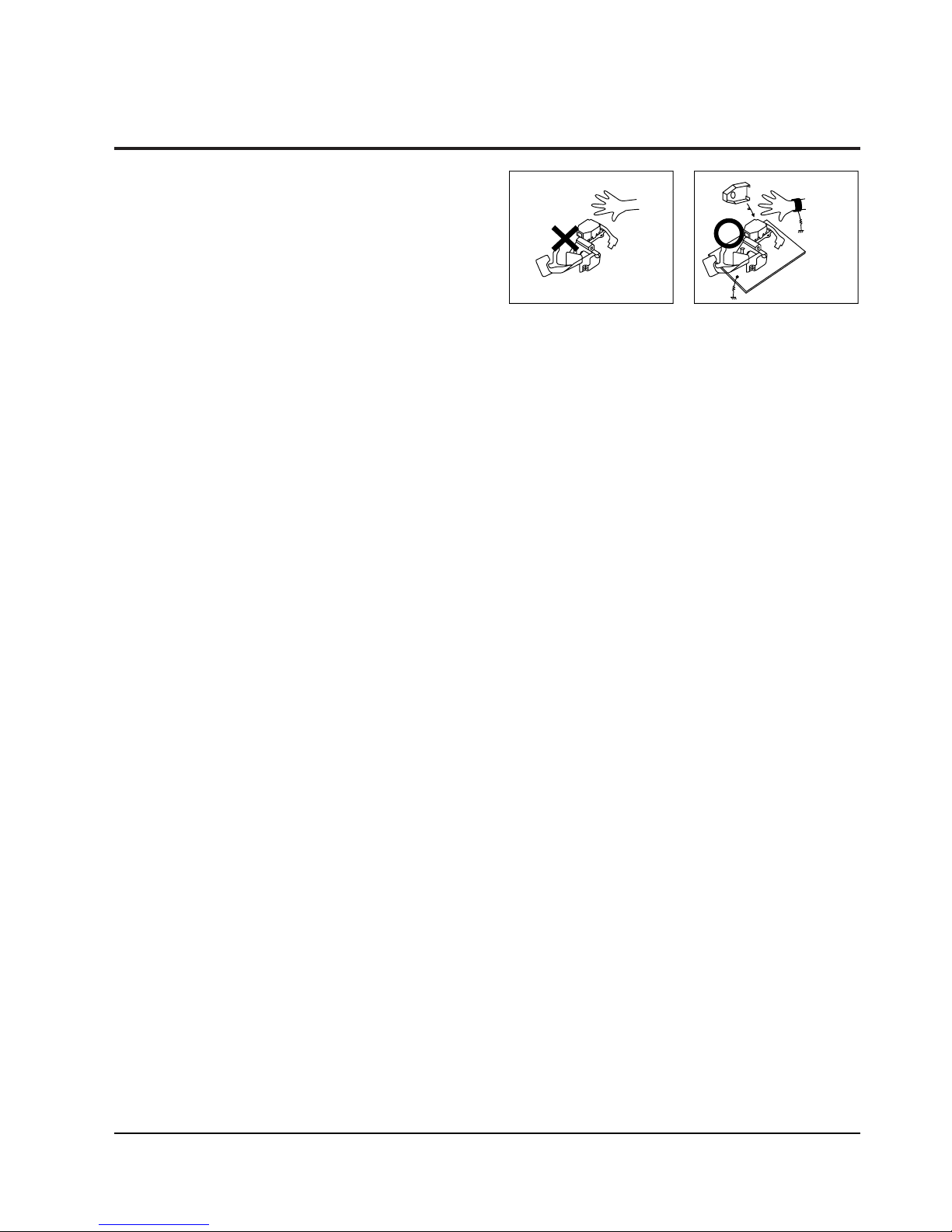
1-4 Handling the optical pick-up
The laser diode in the optical pick up may suffer electrostatic breakdown because of potential static electricity from clothing and your body.
The following method is recommended.
(1) Place a conductive sheet on the work bench (The
black sheet used for wrapping repair parts.)
(2) Place the set on the conductive sheet so that the
chassis is grounded to the sheet.
(3) Place your hands on the conductive sheet(This
gives them the same ground as the sheet.)
(4) Remove the optical pick up block
(5) Perform work on top of the conductive sheet. Be
careful not to let your clothes or any other static
sources to touch the unit.
◆ Be sure to put on a wrist strap grounded to the
sheet.
◆ Be sure to lay a conductive sheet made of copper
etc. Which is grounded to the table.
Fig.1-3
(6) Short the short terminal on the PCB, which is in-
side the Pick-Up ASS’Y, before replacing the PickUp. (The short terminal is shorted when the PickUp Ass’y is being lifted or moved.)
(7) After replacing the Pick-up, open the short termi-
nal on the PCB.
THE UNIT
WRIST-STRAP
FOR GROUNDING
1M
1M
CONDUCTIVE SHEET
Precautions
1-6 Samsung Electronics
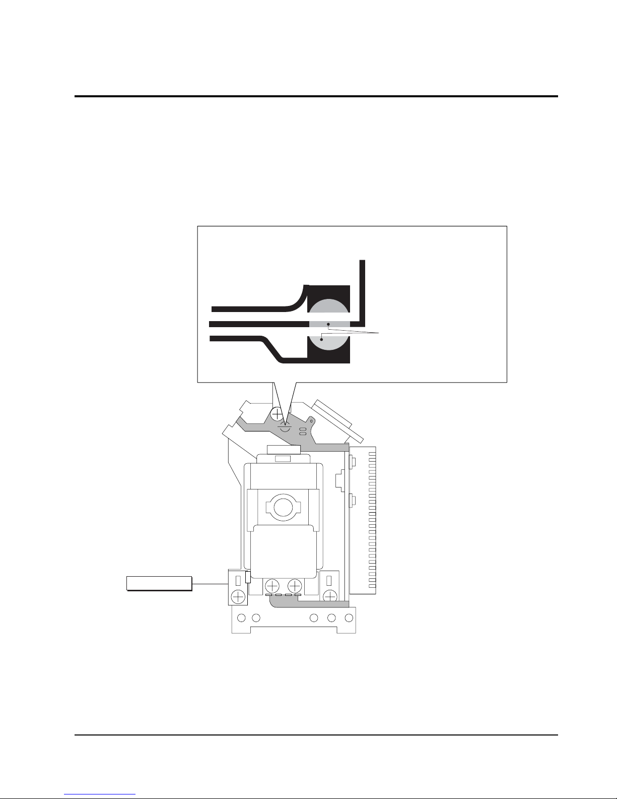
1-5 Pick-up disassembly and reassembly
1-5-1 Disassembly
1) Remove the power cord.
2) Disassemble the Deck-Assy.
3) Make solder land 2 points short on Pick-up.
(See Fig. 1-4)
4) Disassemble the Pick-up.
1-5-2 Assembly
1) Replace the Pick-up.
2) Remove the soldering 2 points on Pick-up.
3) Reassemble the Deck-Assy.
PICK-UP ASS'Y
SOLDER LAND 2 POINTS SHORT
Note : If the assembly and disassembly are not done in correct sequence, the Pick-up may be damaged.
Fig. 1-4

Samsung Electronics
2-1
2. Product Specification
2-1 Product Specification
* : Nominal specification
Power Requirements AC110-240V, 60/50Hz
Power Consumption 10W
General
Weight 1.7Kg
Dimensions 430mm (W) x 207mm (D) x 42mm (H)
Operating Temperature Range +5°C to 35°C
Operating Humidity Range 10% to 75%
DVD
Reading Speed : 3.49 ~ 4.06m/sec.
(Digital Versatile Disc)
Approx. Play Time
(Single Sided, Single Layer Disc) : 135min.
CD : 12Cm Reading Speed : 4.8 ~ 5.6m/sec.
Disc (Compact Disc) Maximum Play Time : 74min.
CD : 8cm Reading Speed : 4.8 ~ 5.6m/sec.
(Compact Disc) Maximum Play Time : 20min.
VCD : 12Cm
Reading Speed : 4.8 ~ 5.6m/sec.
Maximum Play Time : 74min. (Video+Audio)
Composite Video 1 channel ; 1.0Vp-p (75ohm load)
Component Video Y: 1.0 Vp-p (75ohm load)
Pr: 0.70 Vp-p (75ohm load)
Video Output
Pb: 0.70 Vp-p (75ohm load)
S-Video
Luminance Signal : 1.0Vp-p (75ohm load)
Chrominance Signal : 0.3Vp-p (75ohm loa)
2 Channel L(1/L), R(2/R)
*Ferquency Response
48KHz Sampling : 4Hz to 22KHz
Audio Output
96KHz Sampling : 4Hz to 44KHz
*S/N Ratio 110dB
*Dynamic Range 100dB
*Total Harmonic Distortion 0.004%
Product Specification
2-2
Samsung Electronics
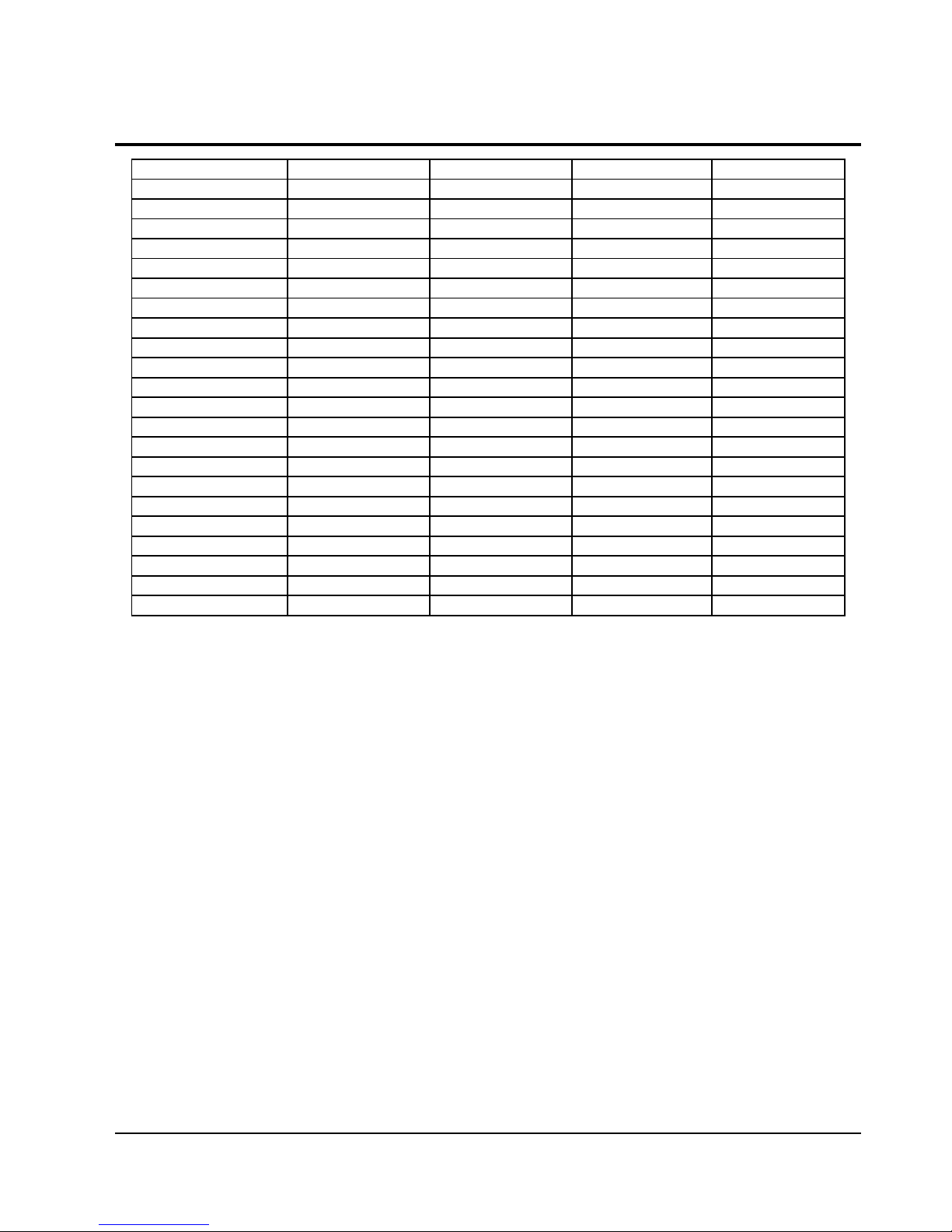
2-2 Chassis Product Specification
MODEL DVD-P250K/XSS DVD-P350K/XSS
FLASH 2M 2M
RF X Ti-D
DRIVE FAN8026 FAN8026
A/V DECODER ZR36862 ZR36778
6dB_AMP LA73054 LA73054
AUDIO DAC PCM1753 PCM1753
AUDIO ADC M65855P M65855P
FRONTMICOM eFHP5842 eFHP5842
MIC INPUT 1MIC 1MIC
NTSC O O
Default PAL PAL
SCARTOUT X X
PSO MULTI MULTI
DTS 2CH/DIGI 2CH/DIGI
D-AUDIO X X
MPEG4 X O
MP3 O O
P-CD O O
WMA O O
VCD O O
SVCD O O
MEMORY CARD X X
DVD-P355K/XAX
2M
Ti-D
FAN8026
ZR36778
LA73054
PCM1753
M65855P
eFHP5842
2MIC
O
NT
X
MULTI
2CH/DIGI
O
O
O
O
O
O
O
X
DVD-P255K/XSS
2M
X
FAN8026
ZR36862
LA73054
PCM1753
M65855P
eFHP5842
2MIC
O
PAL
X
MULTI
2CH/DIGI
X
X
O
O
O
O
O
X
Product Specification
2-3
Samsung Electronics
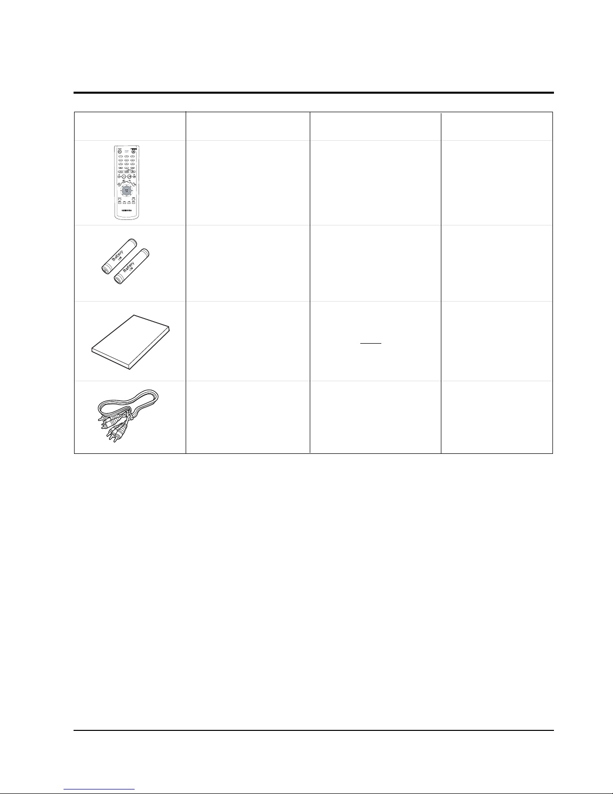
2-3 Option Product Specification
Remote
Control
(AK59-00011E)
Batteries for
Remote Control
(AAA Size)
(AC43-12002H)
User ’s Manual
Video/Audio
Cable
(AC39-42001R)
Description Fig
Description
Parts No Remark
Model Stamdard
of DVD-P350K/XSS
Model Stamdard
of DVD-P350K/XSS
S.N.A
Model Stamdard
of DVD-P350K/XSS
Model Stamdard
of DVD-P350K/XSS
Product Specification
2-4
Samsung Electronics
2-4 Introduction to DVD
2-4-1 The Definition of DVD
DVD is the next generation medium and is the acronym of the Digital Versatile Disc or the Digital Video Disc,
which maximizes the saving density of the disk surface using the MPEG-2 compression technology to enable the
storage of 17G bytes of data on the same size CD.
1) 7 times the storage capacity of the conventional CD
◆ Minimized the track pitch and pit size to 1/2 of conventional CD.
◆ Uses red laser with short-wavelenght of 650nm (635nm).
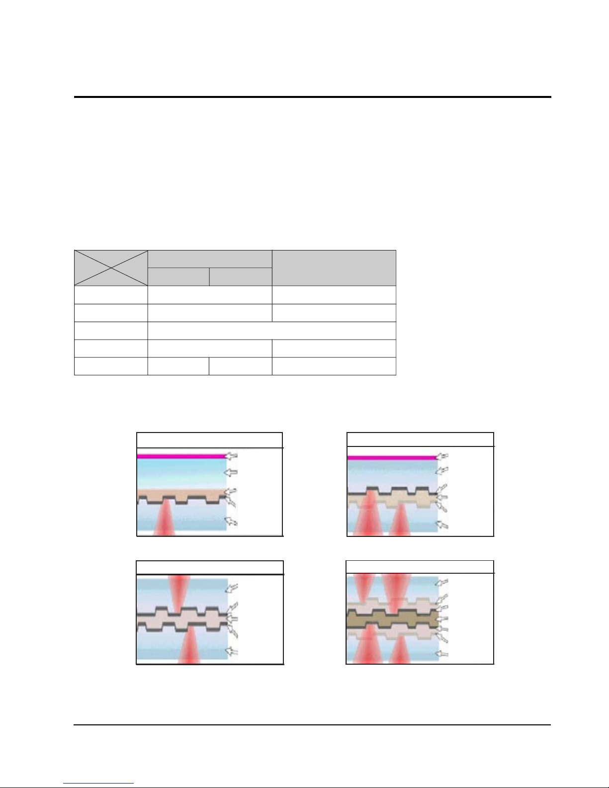
⌘ DVD Vs. CD-ROM
DVD
CD-ROM
Single-Layer Dual-Layer
Laser Wavelength 650nm (635nm) 780nm
Track Pitch 0.75um 1.6um
Disc Diameter 120mm
Disc Thickness 1.2 (0.6 x 2) mm 1.2mm
Linear Velocity 3.49m/s 3.84m/s 1.2 ~ 1.4m/s
2) Disc Formats
DVD consists of two 0.6mm discs attached together, enabling access to the upper and lower side of the disk,
and 4 sides could be used at maximum.
Single Layer : 4.7GByte
Polycarbonate
Label
Bonding layer
Reflective layer
Polycarbonate
Label
Polycarbonate
Bonding layer
Reflective layer
Semi-reflective layer
Polycarbonate
Dual Layer : 8.5GByte
Bonding layer
Reflective layer
Reflective layer
Polycarbonate
Polycarbonate
Dual Side Single Layer : 9.5GByte
Polycarbonate
Bonding layer
Reflective layer
Reflective layer
Semi-reflective layer
Semi-reflective layer
Polycarbonate
Dual Side Dual Layer : 17GByte

Product Specification
2-5
Samsung Electronics
2-4-2 DVD Types
FORMAT TYPE APPLICATIONS
DVD-Video Playback Only High quality image and sound for movies and other video media.
DVD-ROM Read Only Multi-functional, multi-midia software that requires large storage capacity.
DVD-Audio Playback Only High quality sound that exceeds the CD, multi-channel Audio.
DVD-R 1 Time Recording Storage media for the computer.
DVD-RAM Rewritable Data access/storage media for the computer.
Product Specification
2-6
Samsung Electronics
2-5 DVD-Video Fromat
2-5-1 Main Features
1) Able to store up to 160 minutes of Movie by utilizing the MPEG-2 compression technology. ( Aver. 133min.)
2) Enables more than 500 lines of horizontal resolution. (Class corresponding to the Master Tapes used in
broadcasting stations)
3) Provides Dolby Digital 5.1ch Surround 3D sound, which enables theater quality sound (NTSC area).
◆ For PALareas, 1 of either MPEG-2 Audio or Dolby Digital must be selected.
4) Multi-Language
◆ Able to store up to 8 languages of dubbing.
◆ Able to store up to 32 subtitle languages.
5) Milti-Aspect Ratio
3TV Mode alternatives ; 16:9 Wide Screen (DVD Basic)/4:3 Pan & Scan/Letter Box.
6) Multi-Story
Possible to implement Interactive Viewing which enables the user to select the scenario.
7) Multi-Angle
Able to view the camera angle you selected among the scenes recorded with multiple camera angles.
Note ; The above media features must have the DVD Title that contains the appropriate contents to function
properly.
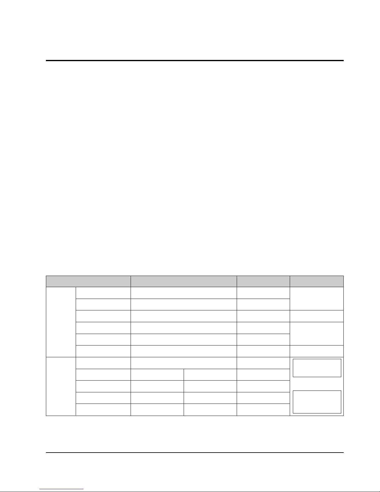
2-5-2 Audio & Video Specifications
Classification DVD-Video Video-CD LD
Compression MPEG-2 MPEG-1
Analog
Pixel 720 x 480 352 x 240
VIDEO
Horizontal resolution Max. 500 Lines Max. 250 Lines Max.420 Lines
Compression rate 1/40 1/140
Analog
Transmission speed Max. 9.8Mbps (variable) 1.15Mbps (fixed)
TV aspect 16:9 / 4:3 4:3 4:3
Audio Max. 8 streams 2CH stereo
Recording type Dolby Digital Linear PCM MPEG-1 Layer 2
AUDIO Transmission rate 448Kbps/stream 6.144Mbps/stream 224Kbps
or
Channel 5.1CH/stream 8CH/stream 2CH
Sampling frequency 48KHz 16, 20, 24Bit/48, 96KHz 16Bit/44.1KHz
2 Analog CH.
2 Digital CH.
(16Bit/44.1KHz)
1 Analog CH.
1 Stream of Dolby Digital
2 Digital CH.
(16Bit/44.1KHz)

Product Specification
2-7
Samsung Electronics
2-5-3 Detailed Feature
As the storage capacity increases, the DVD-Video separates the main data and the additional data such as the
Multi-Function into different data areas, enabling the control of time-data ratio to provide the format that enables
the flexible Software development
◆ 1 Movie (3.5Mbps)
+ Subtitle (1 Language)
+ Surround Audio (1 Language)
= 160min storage (4.673Gbytes)
◆ 1 Movie (3.5Mbps)
+ Subtitle (4 Language)
+ Surround Audio (4 Language)
= 160min storage (4.680Gbytes)
◆ 1 Music Video (4Mbps)
+ 2ch High quality Audio (96kHz/24bit)
= 72min storage (4.648Gbytes)
DVD-Video Feature 1 When Developing the DVD Software, various addition and modification is possible.
DVD-Video uses the variable compresion technology, the MPEG-2 to compress the moving image optimally, minimizing the Data loss to Provide a clear, natural screen while increasing the storage time.
DVD-Video Feature 2 Application of the MPEG-2 compression technology.
◆ MPEG-2 (Variable compression : Max. 1/40)
✓ Field unit compression.
DVD-Video
✓ Compression rate change according to the amount of Data.
✓ Differentiates the still image anf the moving image
compression rete, reducing Data loss and enables
efficient compression.
◆ MPEG-1 (Fixed compression : Max. 1/140)
✓ Frame unit compression.
Video-CD
✓ Compresses all data using the same ratio.
- Fast movements are jagged, and unnatural
Time
Amount of data
Time
Amount of data
Loss area
Product Specification
2-8
Samsung Electronics
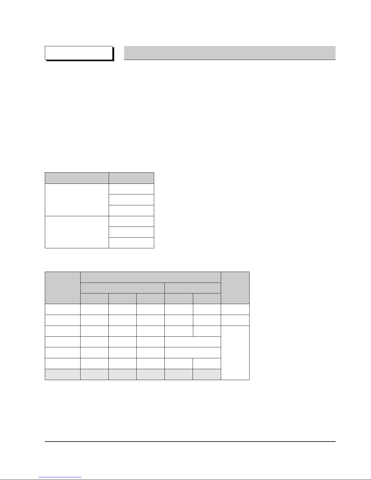
DVD-Video can store the audio using the 5.1ch Dolby Digital compression or the advanced Liner PCM method,
providing the better-than-CD quality and theater like audio quality.
◆ Dolby Digital (AC-3)
✓ Unlike the traditional Dolby pro-Logic method, the Dolby Digital method separates all 5 main channels
(Front L/R, Center, Surround (Rear) L/R)and the Sub woofer to provide live surround audio.
✓ Using the Down Mix method, the conventional Dolby Pro-Logic and Stereo are all compatible.
✓ Each separated channels are played back at CD quality sound. (Frequency band: 20Hz ~ 20KHz)
◆ Linear PCM (Pulse Code Modulation)
✓ Provides the high quality Digital sound without the audio data compression.
✓ Various Digital Recordings are possible as shown in the table to the right.
DVD-Video Feature 3 High quality surround audio.
Sampling Frequency Bit Rate
16bit
48KHz 20bit
24bit
16bit
96KHz 20bit
24bit
◆ Dolby Digital compatible Audio Mode
Audio Coding
Channel Format
Mode
Front Surround (Rear) Remark
LCRLR
1/0 O Mono
2/0 OO Stereo
3/0 OOO
2/1 OOMono
3/1 OOO Mono Surround
2/2 OOOO
3/2 OOOOO
Product Specification
2-9
Samsung Electronics
◆ Audio Dubbing - Max. 8 Languages
◆ Subtitle - Max. 32 Languages. Capable of storing, and selectiong.
◆ Linear PCM (Pulse Code Modulation)
DVD-Video Feature 4 Multi-Language
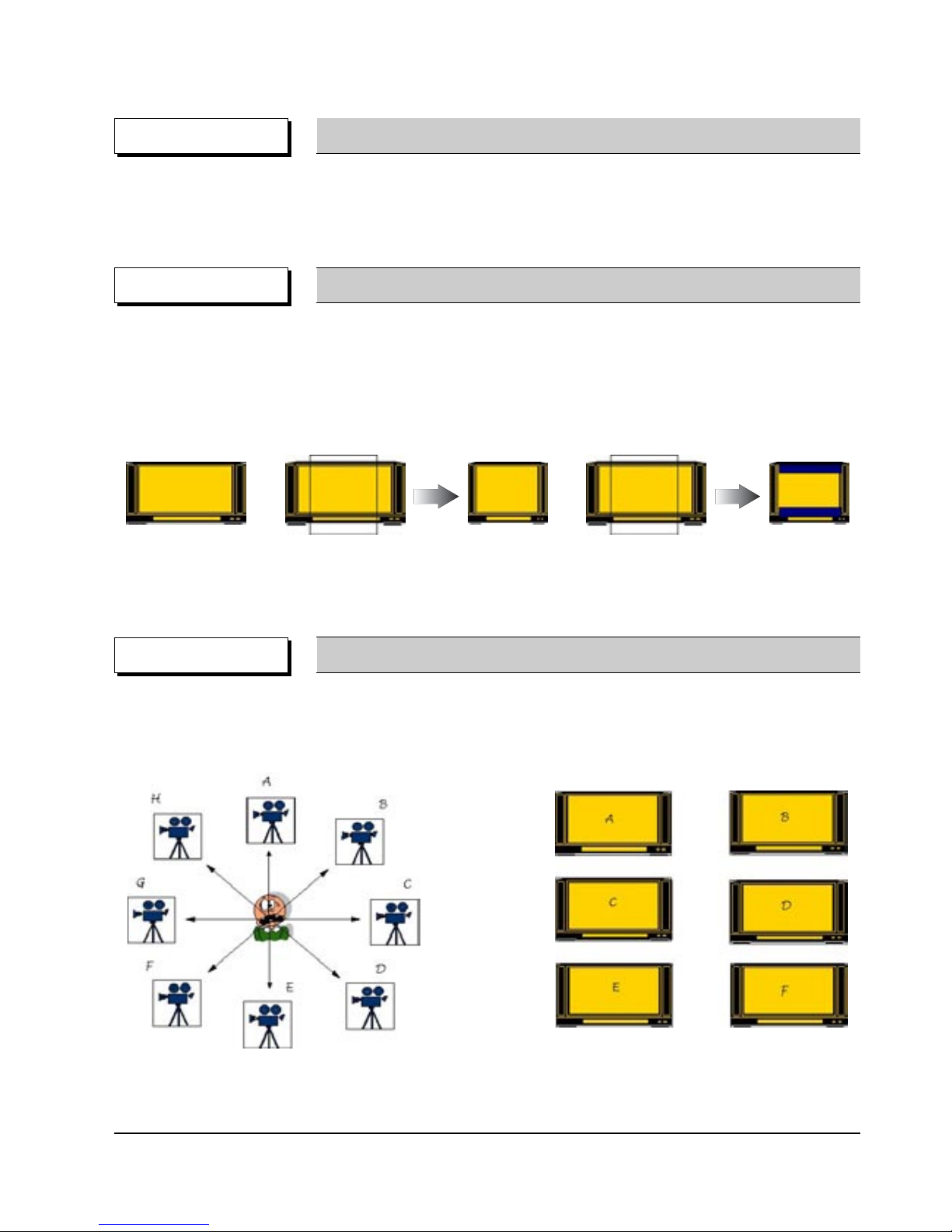
◆ Unlike the conventional VCD or LD, DVD-Video has the default of 16:9 Wide, and can be viewed using the
conventional 4:3 TV, enabling the expansion of viewer selection capabilities.
✓ 16 : 9 TV : Wide Mode (16:9 Wide Full Screen)
✓ 4 : 3 TV : Letter Box Mode, Pan & Scan Mode
DVD-Video Feature 5 Multi-Aspect
4:3 Pan & Scan
16:9 Wide
4:3 Letter Box
◆ Up to 9 angles of view may be stored, enabling the viewer to select a specific viewpoint at a given time.
--> Especially, for the Music Video and Sports Title, this provides a more lively image of the scene.
DVD-Video Feature 6 Multi-Angle
Note ; Only enable to be worked correctly by an appropriate data supported this function in Disc.
Note ; Only enable to be worked correctly by an appropriate data supported this function in Disc.

Product Specification
2-10
Samsung Electronics
◆ DVD-Video provides the enviroment suitable for the bi-directional Software develoment, providing multiple
scenarios. This feature enables the Multi-Story function.
DVD-Video Feature 7
Multi-Story
◆ For the titles that are not suitable for children viewing, Parental Locks are set, requesting user defined
passwords for viewing
◆ Parential Locks may be set on specific frames of the Title, enabling the player to skip those frames during
playback.
OPTION Parental Lock
◆ Classify the world into 6 regions, and if the DVD Title and the Player’s “Reginal Code” do not agree, playback
is prohibited.
⌘ Regionnal Coding is optional for the Soft developers (Region 0 All Code), but the Hardware developers
must adopt the appropriate regionnal code for sale.
✓ Region 1 : The United States and its territories, Canada.
✓ Region 2 : Europe, Japan, Greenland, Egypt, South Africa, the Middle East.
✓ Region 3 : Taiwan, Hongkong, Korea, South East Asia.
✓ Region 4 : Mexico, South America, Australia, New Zealand.
✓ Region 5 : Russia, Eastern Europe, India, Africa.
✓ Region 6 : China.
✓ Region 0 : Worldwide (All Code)
COPYRIGHT Regional Code & Macrovision
◆ Adoptation of the Macrovision System disables the copying on to other media.
Œ
Œ
¨
¨
Œ
´
ˇ
ˆ
Ø
´
´
ˆ

Product Specification
2-11
Samsung Electronics
◆ The image quality of the DVD-Video may vary accoring to the quality of the Master and the Authoring Process
✓ The image quality of the DVD-Video varies according to the Digital Mastering Source such as the
conventional LD, VCD, or Original Film.
✓ Different Authoring Process are used accoring to the Software developers, and this may affect the
DVD image quality.
⌘ Authoring Process
Remark DVD-Video Authoring Process
Video/Audio
Master
Surround Audio
Master
Subtitle
Master
MPEG-2
Encoding
AC-3/MPEG Audio
Encoding
Cutting
Master
Disc
Production
Subtitle
Encoding
Authoring Process
Video/Audio
Subtitle
Multiplexing
bit stream
bit stream
bit stream

Product Specification
2-12
Samsung Electronics
MEMO
Samsung Electronics
12-1
12. Operating Instructions
ENG-8
EZ VIEW
STANDBY/ON
MIN
MIC
VOLUME
MAX
S
ETUP
Description
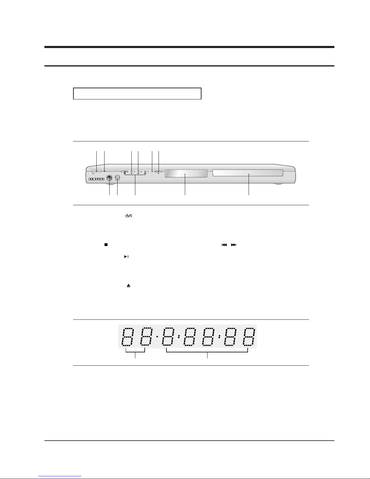
Front Panel Controls
1. STANDBY/ON ( )
When STANDBY/ON is pressed on, the indicator goes
out and the player is turned on.
2. STANDBY indicator
When the unit is first plugged in, this indicator lights.
3. STOP( )
Stops disc play.
4. PLAY/PAUSE ( )
Begin or pause disc play.
5. EZ VIEW
The aspect ratio of a picture can easily be adjusted to
your TV's screen size (16:9 or 4:3).
6. OPEN/CLOSE ( )
Press to open and close the disc tray.
7. MIC
Connect Microphone for karaoke functions.
8. MICROPHONE VOLUME
Use to adjust microphone volume level. Use the button by
pressing it. Turn it to the left or right to control the volume.
9. SKIP( / ) SEARCH
Allow you to search forward/backward through
a disc. Use to skip the title, chapter or track.
10. DISPLAY
Operation indicators are displayed here.
11. DISC TRAY
Place the disc here.
1
879
10
11
23456
Front Panel Display
1. Chapter/Track number indicator
2. Total playing time/Displays various
messages concerning operations
such as PLAY, STOP, LOAD ...
no DISC: No disc loaded.
OPEN: The disc tray is open.
LOAD: Player is loading disc information.
12
Operating Instructions
12-2
ENG-9
Setup
S
ETUP
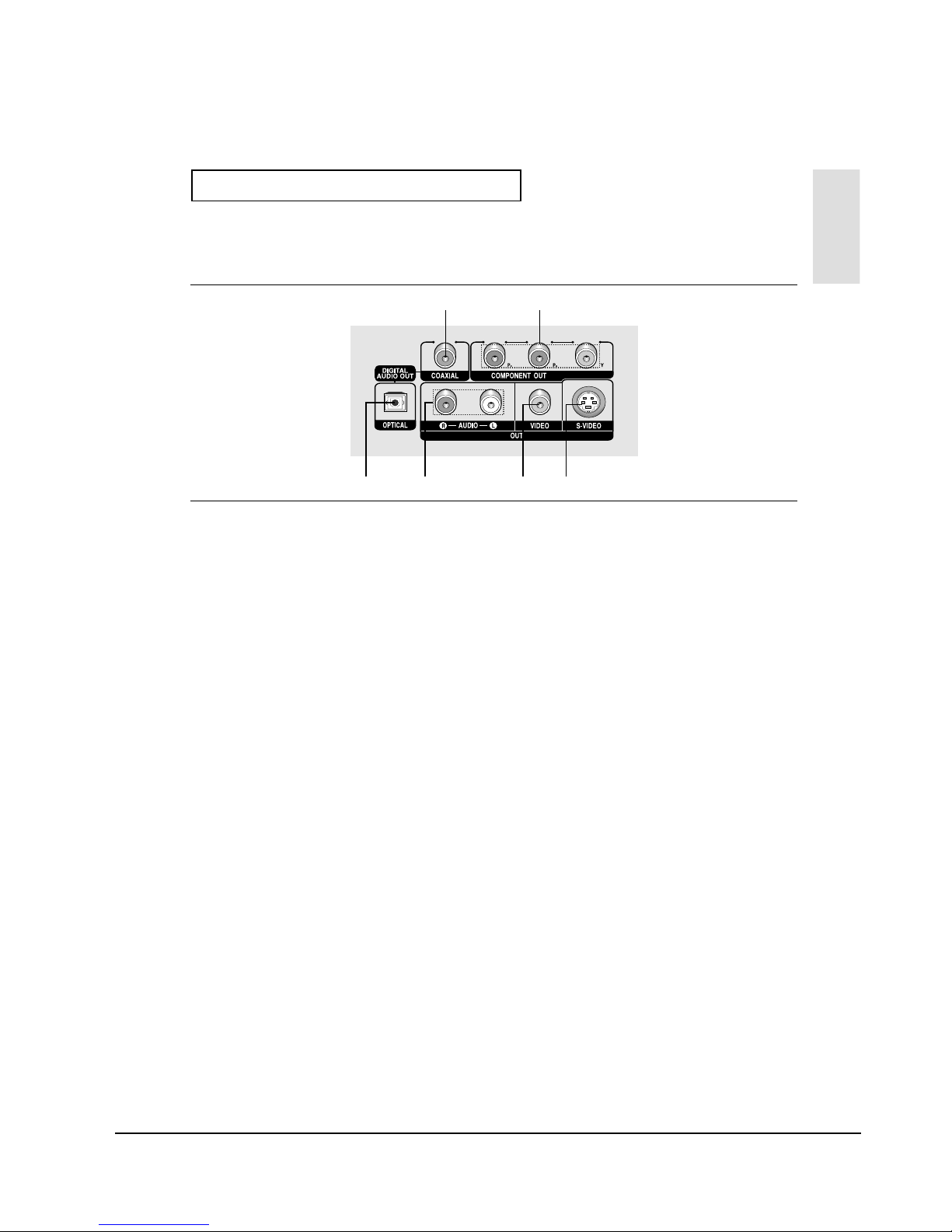
Rear Panel
1. DIGITAL AUDIO OUT JACKS
- Use either an optical or coaxial digital cable to connect
to a compatible Dolby Digital receiver.
- Use either an optical or coaxial digital cable to connect
to an A/V Amplifier that contains a Dolby Digital,
MPEG2 or DTS decoder.
2. COMPONENT VIDEO OUT JACKS
- Use these jacks if you have a TV with Component
Video in jacks. These jacks provide PR, PBand Y video.
- If Component(P-SCAN) Video Output is selected in
Setup Menu, progressive scan mode will work.
- If Component(I-SCAN) Video Output is selected in
Setup Menu, interlaced scan mode will work.
3. AUDIO OUT JACKS
Connect to the Audio input jacks of your television or
audio/video receiver.
4. VIDEO OUT JACK
- Use a video cable to connect to the Video input jack on
your television.
- The Video Output in Setup Menu must be set to
COMPOSITE/S-VIDEO.
5. S-VIDEO OUT JACK
- Use the S-Video cable to connect this jack to the
S-Video jack on your television for higher picture
quality.
- The Video Output in Setup Menu must be set to
COMPOSITE/S-VIDEO.
Note
- Consult your TV User’s Manual to find out if your TV supports Progressive Scan (P-SCAN).
If Progressive Scan is supported, follow the TV User’s Manual regarding Progressive Scan settings in the
TV’s menu system.
- If Component (P-SCAN) Video Output is selected in Setup Menu, Video and S-Video Outputs do not work.
- See pages 52 ~ 53 to get more information on how to use the setup menu.
1
13 45
2
Samsung Electronics
Operating Instructions
12-3
ENG-10
S
ETUP
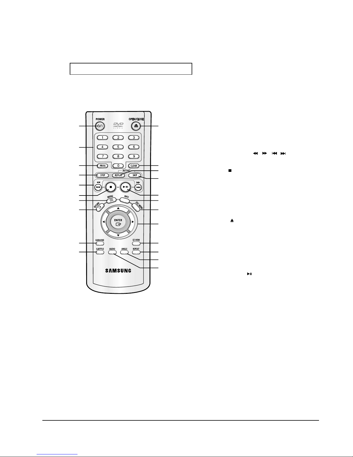
Tour of the Remote Control
1. DVD POWER Button
Turns the power on or off.
2. NUMBER Buttons
3. PROG Button
Allows you to program a specific order.
4. STEP Button
Advances play one frame at a time.
5. SEARCH/SKIP Buttons (
/
,
/
)
Allow you to search forward/backward through a disc.
Use to skip the title, chapter or track.
6. STOP Button ( )
7. MENU Button
Brings up the DVD player’s menu.
8. RETURN Button
Returns to a previous menu.
9. KARAOKE Button
Use to begin Karaoke functions.
10. SUBTITLE Button
11. OPEN/CLOSE ( ) Button
To open and close the disc tray.
12. CLEAR Button
Use to remove menus or status displays from the screen.
13. INSTANT REPLAY Button
This function is used to replay the previous 10 seconds of a
movie from the current position.
14. INSTANT SKIP Button
This function skips playback ahead 10 seconds.
15. PLAY/PAUSE Button ( )
Begin/Pause disc play.
16. INFO Button
Displays the current disc mode.
17. DISC MENU Button
Brings up the Disc menu.
18. ENTER/
…
…†œ √
Buttons
This button functions as a toggle switch.
19. EZ VIEW Button
The aspect ratio of a picture can easily be adjusted according
to the screen size of your TV (16:9 or 4:3).
20. REPEAT Button
Allows you to repeat play a title, chapter, track, or disc.
21. ANGLE Button
Use to access various camera angles on a DVD.
22. AUDIO Button
Use this button to access various audio functions on a disc.
1
2
3
4
5
6
7
8
9
10
11
12
13
14
15
16
17
18
19
20
21
22
Samsung Electronics
Operating Instructions
12-4
ENG-11
Chapter 2
C
ONNECTIONS
Connections
Choosing a Connection
The following shows examples of connections commonly used to connect the DVD player with a TV
and other components.
Before Connecting the DVD Player
- Always turn off the DVD player, TV, and other components before you connect or disconnect any
cables.
- Refer to the user’s manual of the additional components (such as a TV) you are connecting for
more information on those particular components.
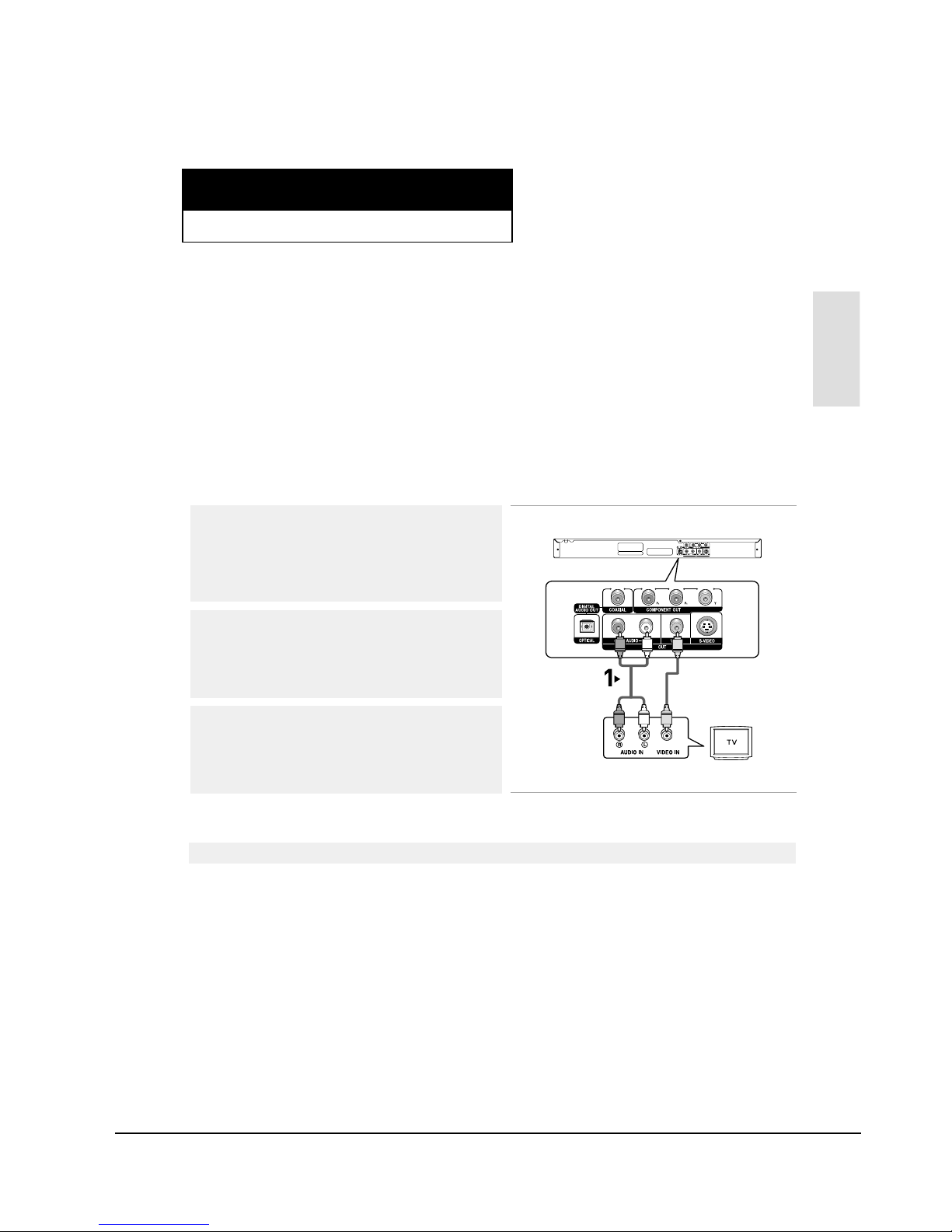
Connection to a TV (Video)
1
Using video/audio cables, connect the VIDEO (yellow)/AUDIO
(red and white) OUT terminals on the rear of the DVD player to
the VIDEO (yellow)/AUDIO (red and white) IN terminals of your
TV.
2
Turn on the DVD player and TV.
3
Press the input selector on your TV remote control until the
Video signal from the DVD player appears on the TV screen.
Note
- Noise may be generated if the audio cable placed too close to the power cable.
- If you want to connect to an Amplifier, please refer to the Amplifier connection page. (See pages 15 to 16)
- The number and position of terminals may vary depending on your TV set.
Please refer to the user's manual of your TV.
- If there is one audio input terminal on the TV, connect it to the [AUDIO OUT][left] (white) terminal of the DVD
player.
RED
WHITE
YELLOW
RED
WHITE
YELLOW
Audio Cable
Video Cable
Samsung Electronics
Operating Instructions
12-5
ENG-12
C
ONNECTIONS
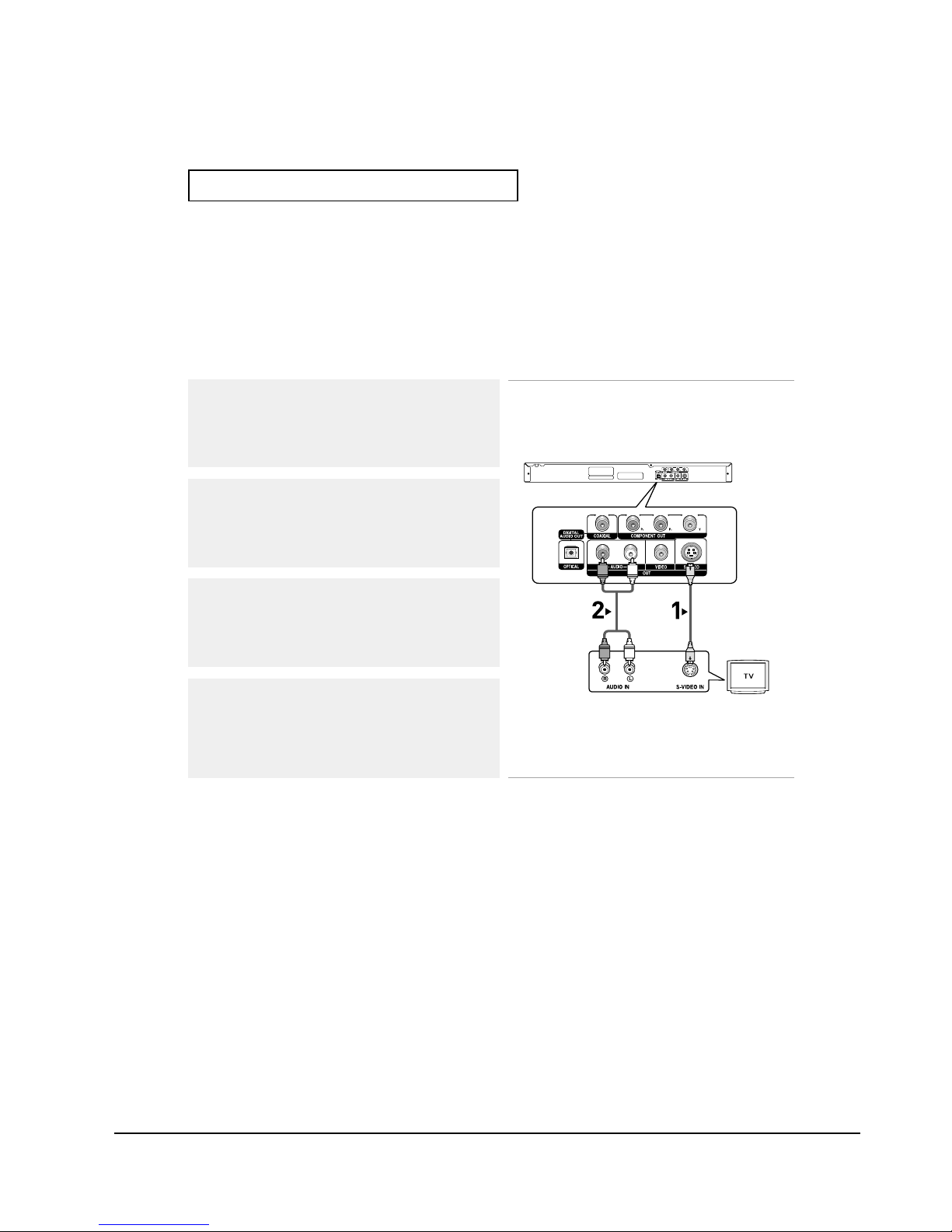
Connection to a TV (S-Video)
-Connecting to your TV using an S-Video cable.
-You will enjoy high quality images. S-Video separates the picture element into black and white(Y)
and color(C) signals to present clearer images than regular video input mode. (Audio signals are
delivered through the audio output.)
Note
- If you want to connect to an Amplifier, please refer to the Amplifier connection page. (See pages 15 to 16)
- The number and position of terminals may vary depending on the TV set.
Please refer to the user's manual of your TV.
1
Using an S-Video cable (not included), connect the S-VIDEO
OUT terminal on the rear of the DVD player to the
S-VIDEO IN terminal of your TV.
2
Using the audio cables, connect the AUDIO (red and white)
OUT terminals on the rear of the DVD player to the AUDIO (red
and white) IN terminals of your TV.
Turn on the DVD player and TV.
3
Press the input selector on your TV remote control until the
S-Video signal from the DVD player appears on your TV
screen.
4
Set the Video Output to COMPOSITE/S-VIDEO in the Display
Setup menu. (See pages 52 to 53)
RED
WHITE
RED
WHITE
Audio Cable
S-Video Cable
(not included)
Samsung Electronics
Operating Instructions
12-6
ENG-13
Connections
C
ONNECTIONS
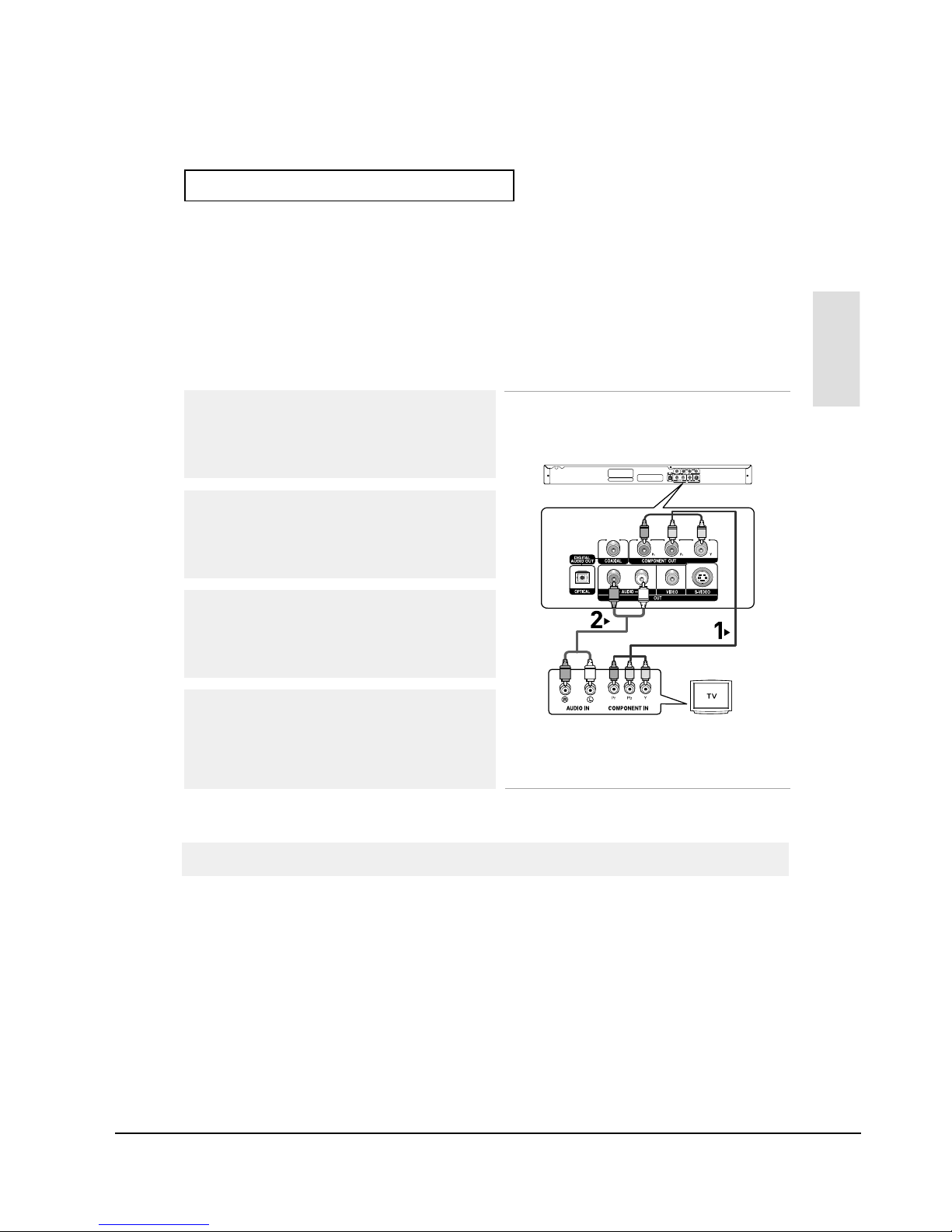
Connection to a TV (Interlace)
-Connecting to your TV using Component video cables.
-You will enjoy high quality and accurate color reproduction images. Component video separates
the picture element into black and white(Y), blue(PB), red(PR) signals to present clear and clean
images. (Audio signals are delivered through the audio output.)
Note
- If Video output is incorrectly set to COMPOSITE/S-VIDEO with the Component cables connected, the
screen will turn red.
- If you want to connect to an Amplifier, please refer to the Amplifier connection page. (See pages 15 to 16)
- The component terminal of your TV may be marked “R-Y, B-Y, Y” or “Cr, Cb, Y” instead of “P
R
, PB, Y”
depending on the manufacturer. The number and position of terminals may vary depending on the TV set.
Please refer to the user's manual of your TV.
1
Using component video cables (not included), connect the
COMPONENT VIDEO OUT terminals on the rear of the DVD
player to the COMPONENT IN terminals of your TV.
2
Using the audio cables, connect the AUDIO (red and white)
OUT terminals on the rear of the DVD player to the AUDIO (red
and white) IN terminals of your TV.
Turn on the DVD player and TV.
3
Press the input selector on your TV remote control until the
Component signal from the DVD player appears on the TV
screen.
4
Set the Video Output to Component (I-SCAN) in the Display
Setup menu. (See pages 52 to 53)
RED WHITE
RED WHITE
RED
BLUE
GREEN
RED
BLUE
GREEN
Audio Cable
Component cable
(not included)
Samsung Electronics

Operating Instructions
12-7
ENG-14
C
ONNECTIONS
Connection to a TV (Progressive)
Note
- What is "Progressive Scan"?
Progressive scan has twice as many scanning lines as the interlace output method.
Progressive scanning method provides better and clearer picture quality.
1
Using component video cables (not included), connect the
COMPONENT VIDEO OUT terminals on the rear of the DVD
player to the COMPONENT IN terminals of your TV.
To see the progressive video output,
You need a TV set supporting the progressive scan input
function. And you have to set up the TV menu to the
progressive scan input.
2
Using the audio cables, connect the AUDIO (red and white)
OUT terminals on the rear of the DVD player to the AUDIO (red
and white) IN terminals of your TV.
Turn on the DVD player and TV.
3
Press the input selector on your TV remote control until the
Component signal from the DVD player appears on the TV
screen.
4
Set the Video Output to Component (P-SCAN) in the Display
Setup menu. (See pages 52 to 53)
- Consult your TV User’s Manual to find out if your TV supports Progressive Scan.
If Progressive Scan is supported, follow the TV User’s Manual regarding Progressive Scan settings
in the TV’s menu system.
- Depending on your TV, the connection method may differ from the illustration above.
RED WHITE
RED WHITE
RED
BLUE
GREEN
RED
BLUE
GREEN
Audio Cable
Component cable
(not included)
Samsung Electronics
Operating Instructions
12-8
ENG-15
Connections
C
ONNECTIONS
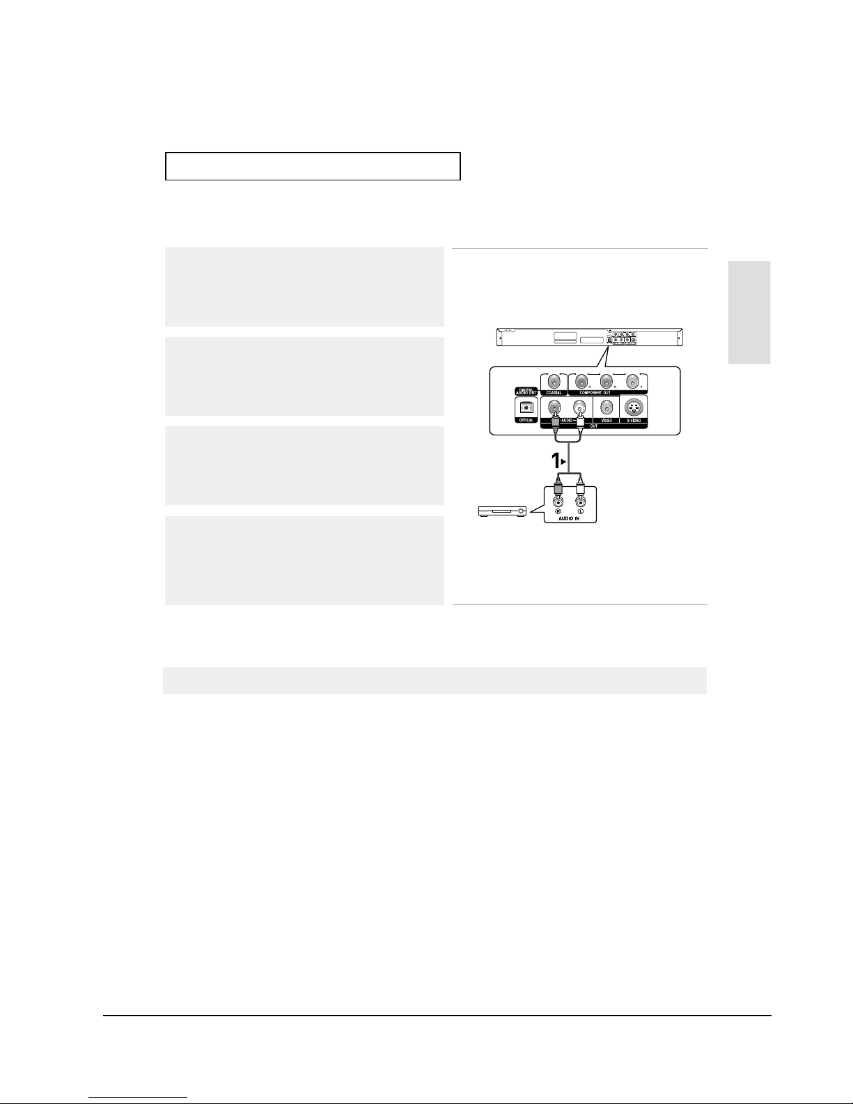
Note
- Please turn the volume down when you turn on the Amplifier. Sudden loud sound may cause
damage to the speakers and your ears.
- Please set the audio in the menu screen according to the Amplifier. (See pages 50 to 51)
- The position of terminals may vary depending on the Amplifier.
Please refer to the user's manual of the Amplifier.
Connection to an Audio System (2 Channel Amplifier)
1
Using the audio cables, connect the AUDIO (red and white)
OUT terminals on the rear of the DVD player to the AUDIO (red
and white) IN terminals of the Amplifier.
2
Using the video signal cable(s), connect the VIDEO, S-VIDEO or
COMPONENT OUT terminals on the rear of the DVD player to
the VIDEO, S-VIDEO or COMPONENT IN terminal of your TV
as described on pages 11 to 14.
3
Turn on the DVD player, TV, and Amplifier.
4
Press the input select button of the Amplifier to select external
input in order to hear sound from the DVD player.
Refer to your Amplifier's user manual to set the Amplifier's
audio input.
RED WHITE
RED WHITE
2-Channel stereo amp
Audio Cable
Samsung Electronics
Operating Instructions
12-9
ENG-16
C
ONNECTIONS
Note
- When you connect the DVD player to DTS Amplifier and play a DTS disc, set the DTS to On in Audio
Setup menu. If it is set to Off, sound will not be heard, or there will be a loud sound.
- Please turn the volume down when you turn on the Amplifier. Sudden loud sound may cause
damage to the speakers and your ears.
-Please set the audio in the menu screen according to the Amplifier. (See pages 50 to 51)
- The position of terminals may vary depending on the Amplifier.
Please refer to the user's manual of the Amplifier.
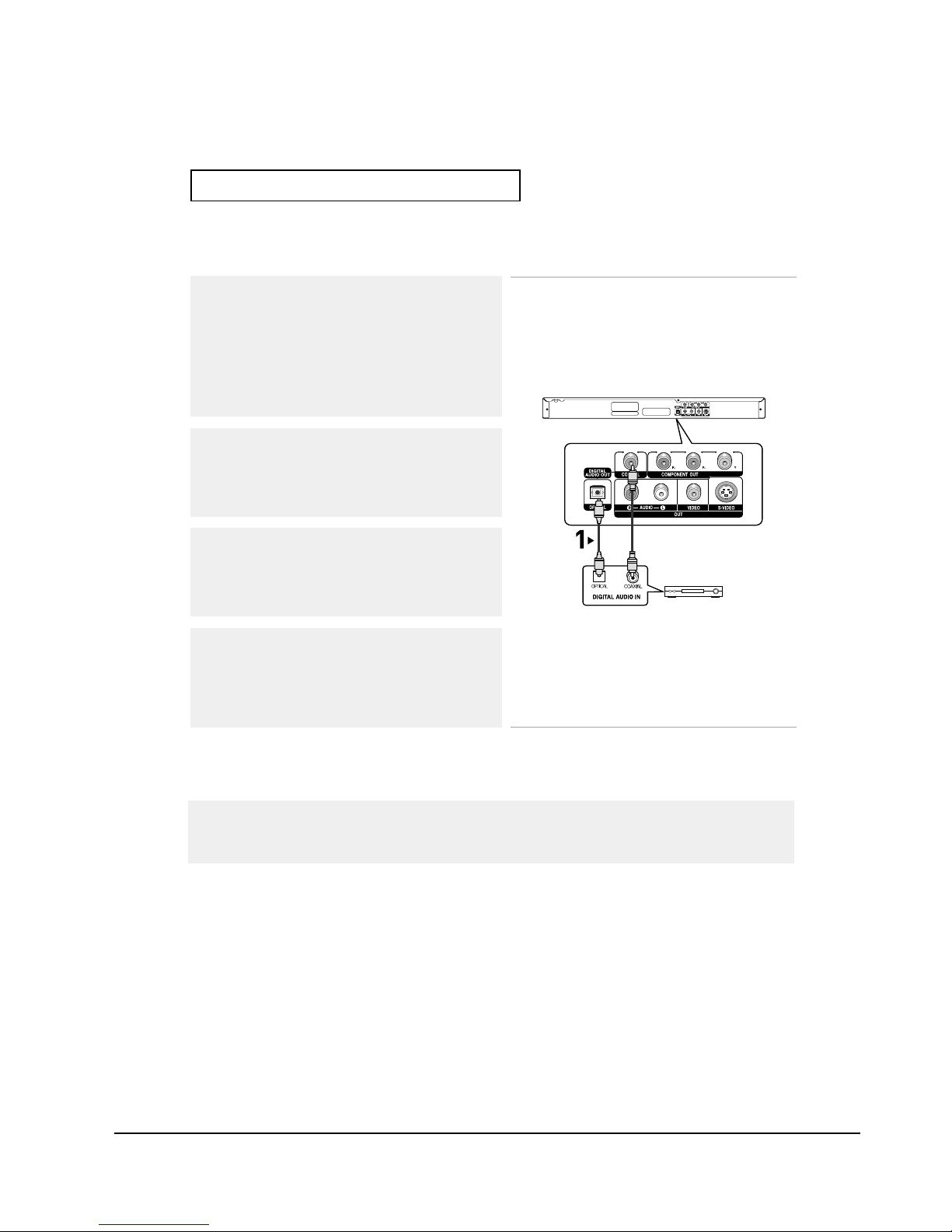
Connection to an Audio System (Dolby digital, MPEG2 or DTS Amplifier)
1
If using an optical cable (not included), connect the DIGITAL
AUDIO OUT (OPTICAL) terminal on the rear of the DVD player
to the DIGITALAUDIO IN (OPTICAL) terminal of the Amplifier.
If using a coaxial cable (not included), connect the DIGITAL
AUDIO OUT (COAXIAL) terminal on the rear of the DVD player
to the DIGITALAUDIO IN (COAXIAL) terminal of the Amplifier.
2
Using the video signal cable(s), connect the VIDEO, S-VIDEO
or COMPONENT OUT terminals on the rear of the DVD player
to the VIDEO, S-VIDEO or COMPONENT IN terminal of your
TV as described on pages 11 to 14.
3
Turn on the DVD player, TV, and Amplifier.
4
Press the input select button of the Amplifier to select external
input in order to hear sound from the DVD player.
Refer to your Amplifier's user manual to set the Amplifier's
audio input.
Optical Cable
(not included)
Coaxial Cable
(not included)
or
Dolby digital or
DTS amp
Samsung Electronics
Operating Instructions
12-10
ENG-17
Chapter 3
B
ASICFUNCTIONS
Basic
Functions
Playing a Disc
Before Play
-Turn on your TV and set it to the correct Video Input on the TV's remote control.
- If you connected an external Audio System, turn on your Audio System and set it to the correct
Audio Input.
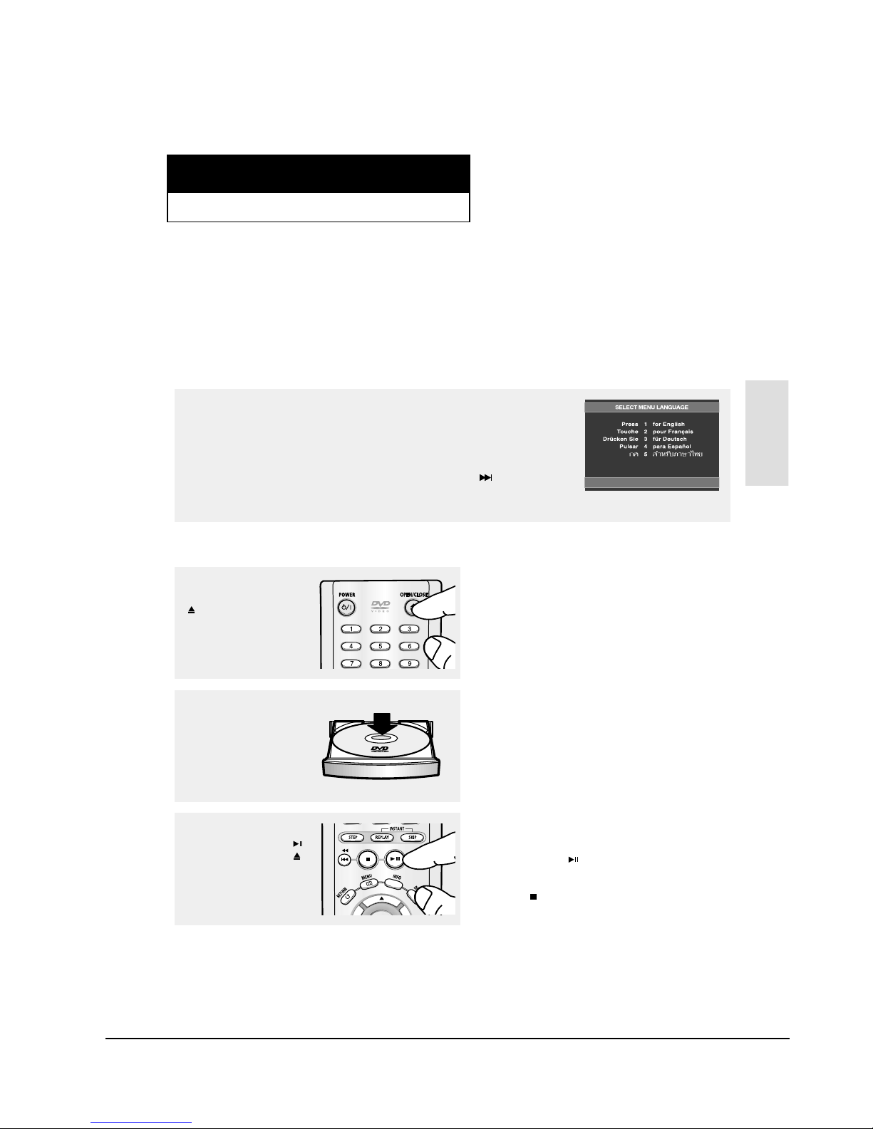
After plugging in the player, the first time you press the DVD POWER button, this screen
comes up: If you want to select a language, press a NUMBER button. (This screen will
only appear when you plug in the player for the first time.)
If the language for the startup screen is not set, the settings may change whenever you
turn the power on or off. Therefore, make sure that you select the language you want to
use.
Once you select a menu language, you can change it by pressing the button on the
front panel of the unit for more than 5 seconds with no disc in the unit. Then the SELECT
MENU LANGUAGE window appears again where you can reset your preferred language.
Playback
1
Press the OPEN/CLOSE
()button.
The STANDBYindicator
light goes out and the tray
opens.
2
Place a disc gently into the
tray with the disc’s label
facing up.
3
Press the PLAY/PAUSE ( )
button or OPEN/CLOSE ( )
button to close the disc tray.
▼
RESUME function
When you stop disc play, the player remembers
where you stopped, so when you press
PLAY/PAUSE ( ) button again, it will pick up
where you left off. (unless the disc is removed
or the player is unplugged, or if you press the
STOP ( ) button twice.)
Samsung Electronics
Operating Instructions
12-11
ENG-18
B
ASICFUNCTIONS
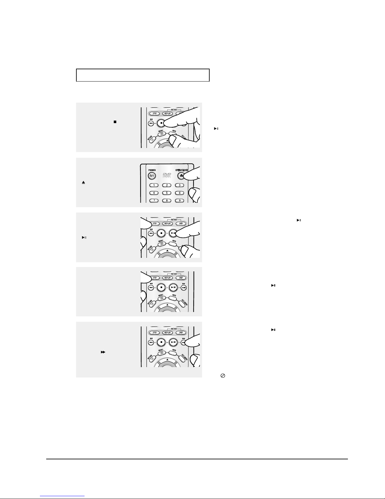
4
Stopping Play
Press the STOP ( ) button
during play.
Note
- If the player is left in the stop mode for more than
one minute without any user interaction, a screen
saver will be activated. Press the PLAY/PAUSE
() button to resume normal play.
- If the player is left in the stop mode for more than
30 minutes, the power will automatically turn off
except when the MIC is connected. (Automatic
Power-Off Function)
Note
This ( ) icon indicates an invalid button press.
6
Pausing Play
Press the PLAY/PAUSE
()or STEP button on the
remote control during play.
▼
Screen stops, no sound.
To resume, press the PLAY/PAUSE ( ) button
once again.
Note
If the player is left for about 5 minutes in pause
mode, it will stop.
7
Step Motion Play (Except
CD)
Press the STEP button on
the remote control during
play.
▼
Each time the button is pressed, a new frame
will appear.
No sound is heard during STEP mode.
Press the PLAY/PAUSE ( ) button to resume
normal play.
You can only perform step motion play in the
forward direction.
▼
No sound is heard during slow mode.
Press the PLAY/PAUSE ( ) button to resume
normal play.
Reverse slow motion play will not work.
8
Slow Motion Play (Except
CD)
Press and hold the
SEARCH ( ) button to
choose the play speed
between 1/8, 1/4 and 1/2 of
normal during PAUSE or
STEP mode.
5
Removing Disc
Press the OPEN/CLOSE
()button.
Samsung Electronics
 Loading...