

Samsung DV455 Series User Manual
Gas and Electric Dryer
user manual
imagine the possibilities
Thank you for purchasing this Samsung product.
To receive more complete service or accessory
parts, please register your product at or contact
www.samsung.com/register
1-800-SAMSUNG (726-7864)
DV455*
This manual is made with 100% recycled paper.
DV455_02836F-08_EN.indd 1DV455_02836F-08_EN.indd 1 2013-12-12 5:11:492013-12-12 5:11:49

English - 2
contents
SAFETY INSTRUCTIONS
4
4 What you need to know about safety
instructions
4 Important safety symbols and precautions
INSTALLING YOUR DRYER
10
10 Unpacking your dryer
10 See exhaust requirements
11 Basic requirements
11 Ducting requirements
12 Important to installer
13 Location considerations
13 Alcove or closet installations
15 Exhausting
16 Gas requirements
16 Commonwealth of massachusetts
installation instructions
17 Electrical requirements
17 Grounding
18 Electrical connections
19 Connecting the inlet hose
21 Replacement parts and accessories
21 Installation
24 Final installation checklist
24 Dryer exhaust tips
25 Door Reversal
OPERATING INSTRUCTIONS, TIPS
27
27 Overview of the control panel
32 Rack Dry
33 Clean the lint fi lter
33 Load the dryer properly
33 Getting started
34 Vent Sensor
35 Setting up Smart control and Smart
monitoring
38 Using the mobile app (Android)
50 Using the mobile app (iOS)
60 Registering your dryer
DV455_02836F-08_EN.indd Sec9:2DV455_02836F-08_EN.indd Sec9:2 2013-12-12 5:11:532013-12-12 5:11:53

English - 3
TROUBLESHOOTING
64
64 Check these points if your dryer…
66 Information codes
67 Network Setup Q&A
CARE AND CLEANING
62
62 Control Panel
62 Tumbler
62 Stainless Steel Tumbler
62 Dryer Exterior
62 Dryer Exhaust System
SPECIAL LAUNDRY TIPS
63
63 Special laundry tips
APPENDIX
69
69 Fabric care chart
70 Protecting the environment
70 Declaration of conformity
70 Specifi cations
71 Cycle chart
72 Open Source Announcement
DV455_02836F-08_EN.indd Sec9:3DV455_02836F-08_EN.indd Sec9:3 2013-12-12 5:11:532013-12-12 5:11:53
English - 4
SAVE THESE INSTRUCTIONS
Safety instructions
Congratulations on your new Samsung Dryer. This manual contains important
information on the installation, use, and care of your appliance. Please take the
time to read this manual to take full advantage of your dryer’s many benefi ts and
features.
WHAT YOU NEED TO KNOW ABOUT SAFETY INSTRUCTIONS
Please read this manual thoroughly to ensure that you know how to operate the extensive features and
functions of your new appliance safely and e ciently. Retain the manual in a safe place near the appliance
for future reference. Use this appliance only for its intended purpose as described in this instruction manual.
The Warnings and Important Safety Instructions in this manual do not cover all possible conditions and
situations that may occur. It is your responsibility to use common sense, caution, and care when installing,
maintaining, or operating your dryer.
Always contact your manufacturer about problems or conditions you do not understand.
IMPORTANT SAFETY SYMBOLS AND PRECAUTIONS
What the icons and signs in this user manual mean:
WARNING
Hazards or unsafe practices that may result in severe personal injury,
death and/or property damage. Follow the information in this manual
to minimize the risk of fi re or explosion or to prevent property damage,
personal injury, or death.
Do not store or use gasoline or other fl ammable vapors and liquids near
this or any other appliance.
CAUTION
Hazards or unsafe practices that may result in personal injury and/or
property damage.
Do NOT attempt.
Do NOT disassemble.
Do NOT touch.
Follow directions explicitly.
Unplug the power plug from the wall socket.
Make sure the machine is grounded to prevent electric shock.
Call the service center for help.
Note
These warning signs are here to prevent injury to you and others.
Please follow them explicitly.
After reading this section, keep it in a safe place for future reference.
DV455_02836F-08_EN.indd Sec11:4DV455_02836F-08_EN.indd Sec11:4 2013-12-12 5:11:532013-12-12 5:11:53
English - 5
SAVE THESE INSTRUCTIONS
01 SAFETY INSTRUCTIONS
WARNING - Risk of Fire
• Clothes dryer installation must be performed by a qualifi ed installer.
• Install the clothes dryer according to the manufacturer’s instructions and local codes.
• Do not install a clothes dryer with fl exible plastic venting materials. If fl exible metal (foil type) duct
is installed, it must be of a specifi c type identifi ed by the appliance manufacturer as suitable for
use with clothes dryers. Flexible venting materials are known to collapse, be easily crushed, and
trap lint. These conditions will obstruct clothes dryer airfl ow and increase the risk of fi re.
• To reduce the risk of severe injury or death, follow all installation instructions.
TO REDUCE THE RISK OF FIRE OR EXPLOSION:
• Do not dry items that have been previously cleaned, washed, soaked, or spotted with
gasoline, dry cleaning solvents, or other fl ammable or explosive substances. They emit
vapors that could ignite or explode. Any material that has been in contact with a cleaning
solvent or fl ammable liquids or solids should not be placed in the dryer until all traces of
these fl ammable liquids or solids and their fumes have been removed.
There are many highly fl ammable items used in homes, such as acetone, denatured alcohol,
gasoline, kerosene, some liquid household cleaners, some spot removers, turpentine, waxes,
and wax removers
• Do not dry items containing foam rubber (may be labeled latex foam) or similarly textured
rubber-like materials on a heat setting. Heated foam rubber materials can, under certain
circumstances, produce fi re by spontaneous combustion.
WHAT TO DO IF YOU SMELL GAS:
• Do not try to light any appliance.
• Do not turn on the appliance.
• Do not touch any electrical switch.
• Do not use any phone in your building.
• Clear the room, building or area of all occupants.
• Immediately call your gas supplier from a neighbor’s phone. Follow the gas supplier’s
instructions.
• If you cannot reach your gas supplier, call the fi re department.
• Installation and service must be performed by a qualifi ed installer, service agency, or the gas
supplier.
WARNING
WARNING
DV455_02836F-08_EN.indd Sec11:5DV455_02836F-08_EN.indd Sec11:5 2013-12-12 5:11:532013-12-12 5:11:53

English - 6
SAVE THESE INSTRUCTIONS
Safety instructions
IMPORTANT SAFTY INSTRUCTION
WARNING
To reduce the risk of fi re, electric shock, or injury to persons when using your appliance, follow
basic precautions, including the following:
1. Read all instructions before using this appliance.
2. Do not dry articles that have been previously cleaned in, washed in, soaked in, or spotted
with gasoline, dry-cleaning solvents, or other fl ammable or explosive substances, because
they give o vapors that could ignite or explode.
3. Do not use the dryer to dry clothes which have traces of any fl ammable substance, such
as vegetable oil, cooking oil, machine oil, fl ammable chemicals, thinner, etc., or anything
containing wax or chemicals, such as mops and cleaning cloths. Flammable substances may
cause the fabric to catch fi re by itself.
4. Do not store or use gasoline or other fl ammable vapors and liquids near this or any other
appliance.
5. Do not allow children or pets to play on, in, or in front of the appliance. Close supervision is
necessary when the appliance is used near children and pets.
6. Before the appliance is removed from service or discarded, remove the door to the drying
compartment to prevent children or animals from becoming trapped inside.
7. Do not reach into the appliance when the drum is moving.
8. Do not install or store this appliance where it will be exposed to the weather.
9. Do not tamper with the controls.
10. Do not repair or replace any part of the appliance or attempt any servicing unless specifi cally
recommended in the user-maintenance instructions or published in the user-repair
instructions that you understand and have the skills to carry out.
11. Do not use fabric softeners or products to eliminate static unless recommended by the
manufacturer of the fabric softener or product.
12. Clean the lint screen before or after each load.
13. Do not use heat to dry articles containing foam rubber or similarly textured rubber-like
materials.
14. Keep the area around the exhaust opening and surrounding areas free from lint, dust, and
dirt.
15. The interior of the dryer and exhaust duct should be cleaned periodically by qualifi ed service
personnel.
16. Do not place items exposed to cooking oils in your dryer. Items contaminated with cooking
oils may contribute to a chemical reaction that could cause a load to catch fi re.
17. This appliance must be grounded. See “Electrical requirements” and ”Grounding” in the
“Installing your dryer” section.
18. This appliance must be properly grounded. Never plug the power cord into a receptacle
that is not grounded adequately and in accordance with local and national codes. Refer to
installation instructions for grounding this appliance.
WARNING
DV455_02836F-08_EN.indd Sec11:6DV455_02836F-08_EN.indd Sec11:6 2013-12-12 5:11:532013-12-12 5:11:53
English - 7
SAVE THESE INSTRUCTIONS
01 SAFETY INSTRUCTIONS
19. Ensure pockets are free from small irregularly shaped hard objects and foreign material, i.e.
coins, knives, pins, etc. These objects could damage your dryer.
20. Gas leaks may occur in your system, resulting in a dangerous situation.
21. Gas leaks may not be detected by smell alone.
22. Gas suppliers recommend you purchase and install a UL-approved gas detector.
GAS APPLIANCES :
This product contains chemicals known to the State of California to cause cancer and
reproductive toxicity.
Gas appliances can cause low-level exposure to Proposition 65 listed substances, including but
not limited to, benzene, carbon monoxide, formaldehyde and soot, substances resulting from the
incomplete combustion of natural gas or LP fuels.
CAUTION
1. Do not sit on top of the dryer.
2. Because of continuing product improvements, Samsung reserves the right to change
specifi cations without notice. For complete details, see the Installation Instructions packed
with your product before selecting cabinetry, making cutouts, or beginning installation.
3. Do not wash clothing with large buckles, buttons, or other heavy metal or solid things.
4. Install and use in accordance with the manufacturer’s instructions.
5. Do not place items in your dryer that have been spotted or soaked with vegetable oil or
cooking oil. Even after being washed, these items may contain signifi cant amounts of these
oils.
6. Residual oil on clothing can ignite spontaneously. The potential for spontaneous combustion
increases when items containing vegetable oil or cooking oil are exposed to heat. Heat
sources such as your dryer can warm these items, allowing an oxidation reaction in the oil to
occur. Oxidation creates heat. If this heat cannot escape, the items can become hot enough
to catch fi re. Piling, stacking, or storing these kinds of items may prevent heat from escaping
and can create a fi re hazard.
7. All washed and unwashed fabrics that contain vegetable oil or cooking oil can be dangerous.
Washing these items in hot water with extra detergent will reduce, but not eliminate, the
hazard. Always use the Cool Down cycle for these items to reduce their temperature. Never
remove these items from the dryer hot or interrupt the drying cycle until the items have run
through the Cool Down cycle. Never pile or stack these items when they are hot.
8. Take care that children’s fi ngers are not caught in the door when closing it. This may result in
injury.
WARNING
CAUTION
DV455_02836F-08_EN.indd Sec11:7DV455_02836F-08_EN.indd Sec11:7 2013-12-12 5:11:532013-12-12 5:11:53

English - 8
SAVE THESE INSTRUCTIONS
Safety instructions
REGULATORY NOTICE
1. FCC Notice
FCC CAUTION:
Any changes or modifi cations not expressly approved by the party responsible for compliance
could void the user’s authority to operate the equipment.
This device complies with Part 15 of FCC Rules. Operation is subject to the following two
conditions:
1. This device may not cause harmful interference, and
2. This device must accept any interference received including interference that causes
undesired operation.
For product available in the USA/Canada market, only channel 1~11 can be operated. Selection
of other channels is not possible.
FCC STATEMENT:
This equipment has been tested and found to comply within the limits for a Class B digital
device, pursuant to part 15 of the FCC Rules. These limits are designed to provide reasonable
protection against harmful interference in a residential installation.
This equipment generates, uses, and can radiate radio frequency energy and, if not installed
and used in accordance with the instructions, may cause harmful interference to radio
communications. However, there is no guarantee that interference will not occur in a particular
installation. If this equipment does cause harmful interference to radio or television reception,
which can be determined by turning the equipment o and on, the user is encouraged to try to
correct the interference by one or more of the following measures:
• Reorient or relocate the receiving antenna
• Increase the separation between the equipment and receiver
• Connect the equipment to an outlet on a di erent circuit from that of the receiver.
• Consult the dealer or an experienced radio/TV technician for help.
FCC RADIATION EXPOSURE STATEMENT:
This equipment complies with FCC radiation exposure limits set forth for an uncontrolled
environment. This equipment should be installed and operated with a minimum distance of 20cm
between the radiator and your body. This device and its antenna(s) must not be co-located or
operated in conjunction with any other antenna or transmitter.
CAUTION
DV455_02836F-08_EN.indd Sec11:8DV455_02836F-08_EN.indd Sec11:8 2013-12-12 5:11:532013-12-12 5:11:53

English - 9
SAVE THESE INSTRUCTIONS
01 SAFETY INSTRUCTIONS
2. IC Notice
The term “IC” before the radio certifi cation number only signifi es that Industry Canada technical
specifi cations were met. Operation is subject to the following two conditions: (1) this device may
not cause interference, and (2) this device must accept any interference, including interference
that may cause undesired operation of the device.
This Class B digital apparatus complies with Canadian ICES-003.
Cet appareil numérique de la classe B est conforme á la norme NMB-003 du Canada.
For product available in the USA/Canada market, only channels 1~11 can be operated. Selection
of other channels is not possible.
IC RADIATION EXPOSURE STATEMENT:
This equipment complies with IC RSS-102 radiation exposure limits set forth for an uncontrolled
environment. This equipment should be installed and operated with minimum distance of 20
cm between the radiator & your body. This device and its antenna(s) must not be co-located or
operated in conjunction with any other antenna or transmitter.
DV455_02836F-08_EN.indd Sec11:9DV455_02836F-08_EN.indd Sec11:9 2013-12-12 5:11:532013-12-12 5:11:53
English - 10
Installing your dryer
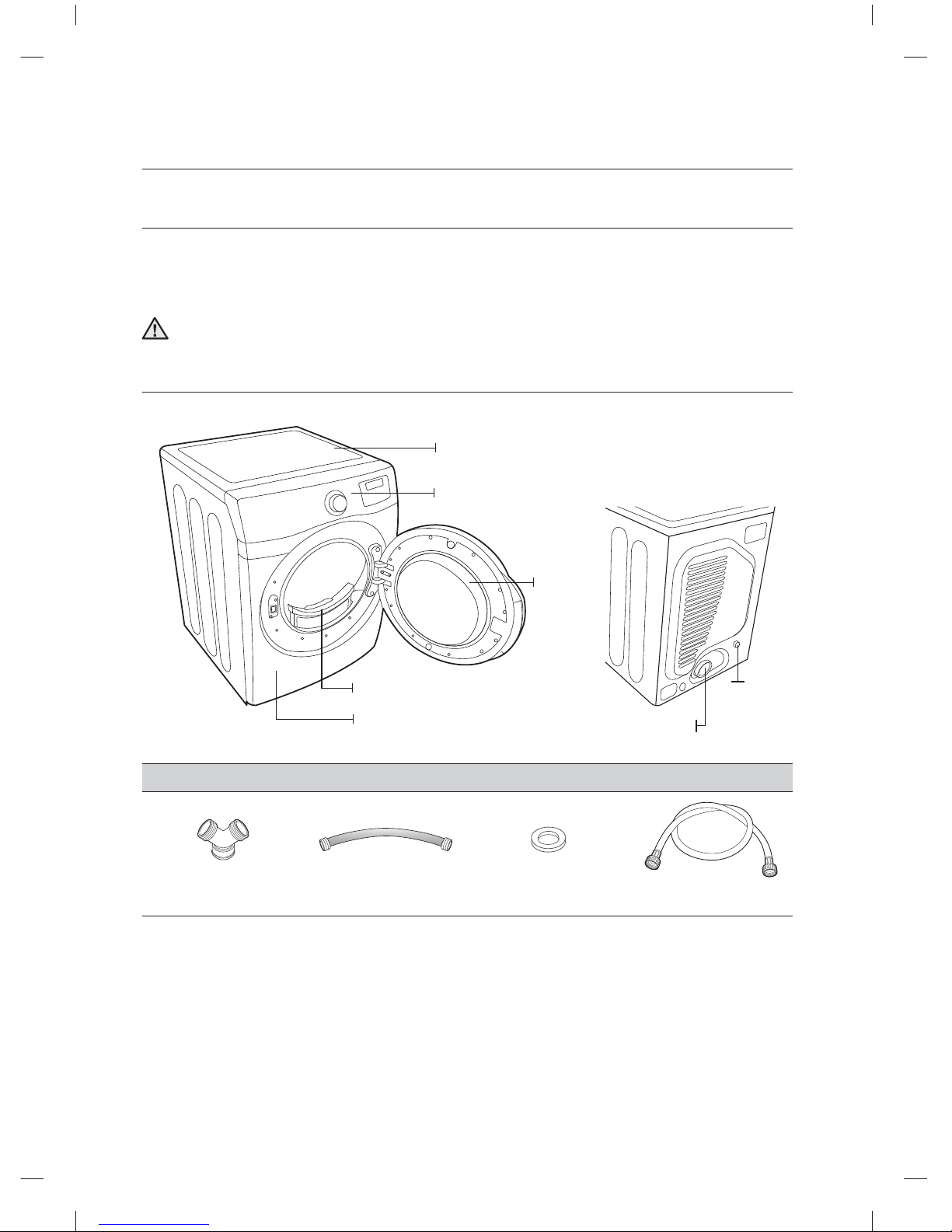
UNPACKING YOUR DRYER
Unpack your Dryer and inspect it for shipping damage. Make sure you have received all the items
shown below. If your Dryer was damaged during shipping, or you do not have all the items, contact
1-800-SAMSUNG (726-7864).
To prevent personal injury or strain, wear protective gloves whenever lifting or carrying the unit.
The packing materials can be dangerous children. Keep all packaging material (plastic bags,
polystyrene, etc.) well out of the reach of children.
SEE EXHAUST REQUIREMENTS
Parts supplied
“Y”-connector Short inlet hose Rubber Washer Long inlet hose
WARNING
Control panel
Top Cover
Door
Frame Front
Filter
Duct Exhaust
Water Inlet
[ BACK ]
DV455_02836F-08_EN.indd 10DV455_02836F-08_EN.indd 10 2013-12-12 5:11:532013-12-12 5:11:53
English - 11
02 INSTALLING YOUR DRYER
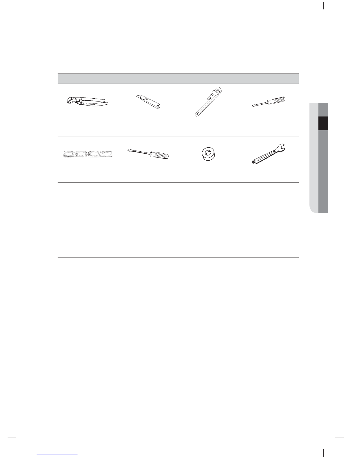
Tools needed
Pliers Cutting knife
Pipe wrench
(gas only)
Nut drivers
Level Phillips Screwdriver Duct tape Wrench
BASIC REQUIREMENTS
Make sure you have everything necessary for the proper installation
• A GROUNDED ELECTRICAL OUTLET is required. Refer to the “Electrical requirements” section on
page 17.
• A POWER CORD electric dryer (except for Canada).
• GAS LINES (if a gas dryer) must meet national and local codes.
• The EXHAUST SYSTEM must be made of rigid metal or fl exible sti -walled metal exhaust ducting.
DUCTING REQUIREMENTS
• Use a 4-inch (10.2 cm) diameter rigid aluminum or rigid galvanized steel duct.
• Do not use a smaller duct.
• Ducts larger than 4 inches (10.2 cm) in diameter can result in increased accumulation of lint.
• Lint should be removed regularly.
• If a fl exible metal duct must be used, use the type with a sti sheet metal wall. Do not use a fl exible duct
with a thin foil wall. A serious blockage can result if the fl exible metal duct is bent too sharply.
• Never install any type of fl exible duct in walls, ceilings, or other concealed spaces.
• Keep the exhaust duct as straight and short as possible.
• Secure joints with duct tape. Do not use screws.
• Plastic fl exible ducts can kink, sag, be punctured, reduce airfl ow, extend drying times, and a ect the
dryer operation.
• Exhaust systems longer than recommended can extend drying times, a ect machine operations, and
collect lint.
• The exhaust duct should end with an exhaust hood with a swing-out damper to prevent back drafts and
entry of wildlife. Never use an exhaust hood with a magnetic damper.
• The hood should have at least 12 inches (30.5 cm) of clearance between the bottom of the hood and
the ground or other obstruction. The hood opening should point down.
• Never install a screen over the exhaust outlet.
• To avoid lint buildup, do not exhaust the dryer directly into a window well. Do not exhaust under a house
or porch.
• If the exhaust duct must run through an unheated area, the duct should be insulated and slope slightly
down towards the exhaust hood to reduce condensation and lint buildup.
DV455_02836F-08_EN.indd 11DV455_02836F-08_EN.indd 11 2013-12-12 5:11:532013-12-12 5:11:53
English - 12
Installing your dryer
• Inspect and clean the interior of the exhaust system at least once a year. Unplug the power cord before
cleaning.
• Check frequently to make sure the exhaust hood damper opens and closes freely.
• Check once per month, and clean at least once per year. Note: If your clothes are not getting dry, then
check the ducting for obstructions.
• Do not exhaust the dryer into a wall, ceiling, crawl space, or concealed space of a building, gas vent, or
any other common duct or chimney. This could create a fi re hazard from the lint expelled by the dryer.
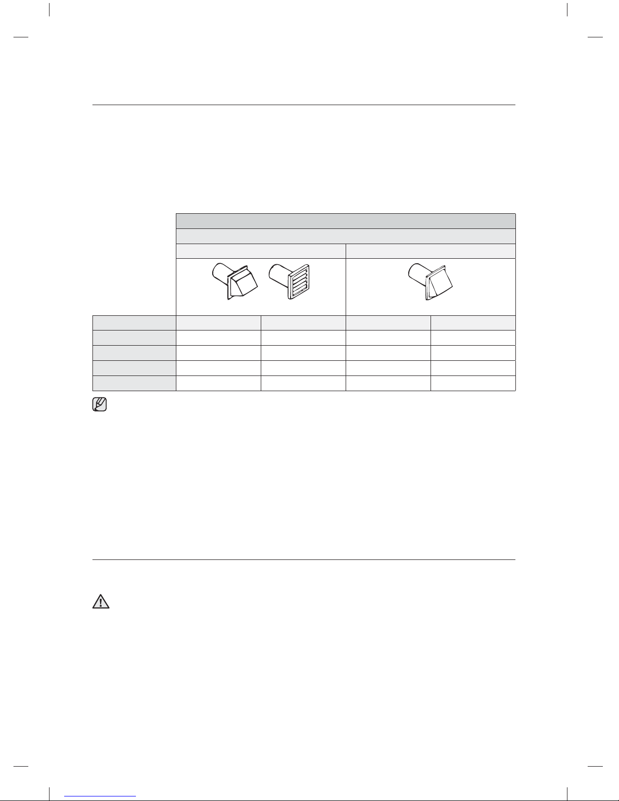
ELECTRIC AND GAS DRYER
Weather Hood Type
Recommended
Use only for short-run installation
4” (10 .16 cm)
2.5” (6.35 cm)
No. of 90° elbows
Rigid Metallic Flexible*
Rigid Metallic Flexible*
0
24.4 m (80 ft.) 12.4 m (41 ft.)
22.6 m (74 ft.) 10.1 m (33 ft.)
1
20.7 m (68 ft.) 11.2 m (37 ft.)
18.9 m (62 ft.) 8.8 m (29 ft.)
2
17.4 m (57 ft.) 10.1 m (33 ft.)
15.5 m (51 ft.) 7.6 m (25 ft.)
3
14.3 m (47 ft.) 9.0 m (29 ft.)
12.5 m (41 ft.) 6.5 m (21 ft.)
* Do not use non-metallic fl exible ducts.
If the new dryer is installed into an existing exhaust system you must make sure:
• The exhaust system meets all local, state, and national codes.
• That a fl exible plastic duct is not used.
• To inspect and clean all lint buildup from inside the existing duct.
• The duct is not dented or crushed.
• The exhaust hood damper opens and closes freely.
The static pressure in any exhaust system must not exceed 0.83 inches of water column, or be less than 0.
This can be measured with the dryer running with a manometer at the point where the exhaust duct
connects to the dryer. A no-heat setting should be used. The dryer tumbler should be empty and the lint
fi lter clean.
IMPORTANT TO INSTALLER
Please read the following instructions carefully before installing the dryer. These instructions should be kept
for future reference.
Remove the door from all discarded appliances to avoid the danger of a child being trapped and
su ocating.
WARNING
DV455_02836F-08_EN.indd 12DV455_02836F-08_EN.indd 12 2013-12-12 5:11:542013-12-12 5:11:54
English - 13
02 INSTALLING YOUR DRYER
LOCATION CONSIDERATIONS
The dryer should be located where there is enough space at the front for loading the dryer, and enough
space behind for the exhaust system. This dryer is factory-ready for the rear exhaust option. To exhaust out
the bottom, right or the left, use the accessory exhaust kit. Instructions are included with the kit. Make sure
the room in which the dryer is located has enough fresh air. The dryer must be located where there are no
air-fl ow obstructions.
For gas dryers, adequate clearance must be maintained as noted on the data plate to ensure adequate air
for combustion and the proper dryer operation.
The dryer must not be installed or stored in an area where it will be exposed to water and/or weather. The
dryer area must be kept clear of combustible materials, gasoline, and other fl ammable vapors and liquids. A
dryer produces combustible lint. The area around the dryer should be kept lint-free.
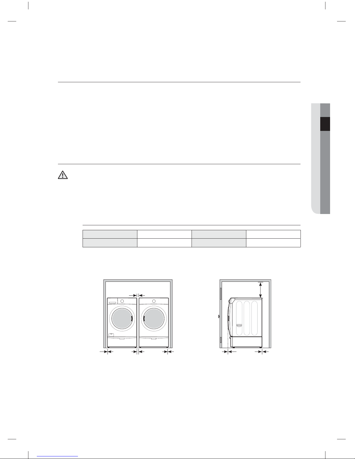
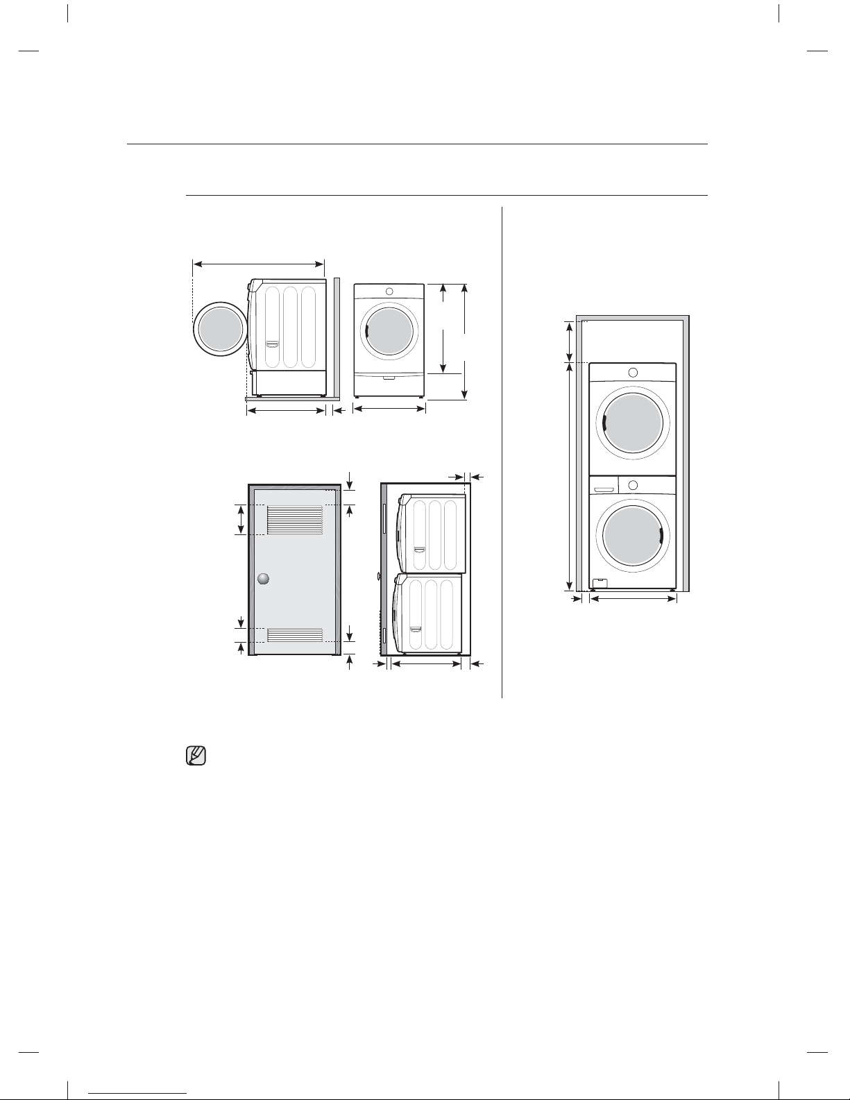
ALCOVE OR CLOSET INSTALLATIONS
The dryer must be exhausted to the outside to reduce the risk of fi re when installed in an alcove or
closet.
• No other fuel-burning appliance should be installed in the same closet as the dryer.
• WARNING: To reduce the risk of fi re, this dryer must be exhausted to the outside. Refer to the
“Exhausting” section on page 15.
Minimum clearances between the dryer and adjacent walls or other
surfaces
Sides 1 in / 25 mm Rear 5 in / 127 mm
Top 17 in / 432 mm Front 2 in / 51 mm
• The front of the closet must have two unobstructed air openings for a combined minimum
total area of 72 in² (465 cm²) with a minimum clearance of 3” (7.6 cm) at the top and bottom.
A slatted door with equivalent space clearances is acceptable.
Recessed area Side view - closet or confi ned area
1 in.
(2.5 cm)
1 in.
(2.5 cm)
1 in.
(2.5 cm)
27 in.
(68.6 cm)
27 in.
(68.6 cm)
2 in.
(5 cm)
5 in.
(12.7 cm)
34.1 in.
(86.5 cm)
17 in.
(43.2 cm)
WARNING
DV455_02836F-08_EN.indd 13DV455_02836F-08_EN.indd 13 2013-12-12 5:11:542013-12-12 5:11:54
English - 14
Installing your dryer
With optional pedestal base or stacking kit
Required Dimensions for Installation With Pedestal
Required Dimensions for Installation
With Stacking Kit
27 in.
(68.6 cm)
39 in.
(99 cm)
5 in.
(12.7 cm)
34.1 in.
(86.5 cm)
51.2 in. (130 cm) to clear open door
53.6 in.
(136.2 cm)
1 in.
(2.5 cm)
27 in.
(68.6 cm)
77.2 in.
(196.2 cm)
6 in. *
(15.2 cm)
48 in.² *
(310 cm²)
24 in.² *
(155 cm²)
3 in.
(7.6 cm)
3 in.
(7.6 cm)
1 in.
(2.5 cm)
34.1 in.
(86.5 cm)
8 in.**
(20.3 cm)
5 in.
(12.7 cm)
Closet or Door
* Required spacing
** An external exhaust elbow requires additional space.
It is not recommended to stack DV457* on your washer.
(it might be hard to control dryer LCD because of the viewing angle.)
DV455_02836F-08_EN.indd 14DV455_02836F-08_EN.indd 14 2013-12-12 5:11:542013-12-12 5:11:54
English - 15
02 INSTALLING YOUR DRYER
EXHAUSTING
The dryer shall not be exhausted into a chimney, a wall, a ceiling, an attic, a crawl space, or a concealed
space of a building.
Exhausting the dryer to the outside will prevent large amounts of lint and moisture from being blown into the
room.
Refer to the “Ducting requirements” section on page 11 for the maximum duct length and
number of bends.
• All dryers must be exhausted to the outside.
• Do not assemble the duct with screws or other fastening means that extend into the
duct and catch lint.
• The exhaust duct should be 4 inches (102 mm) in diameter.
• The total length of fl exible metal duct shall not exceed 2.4 m (7.8 ft.).
In the United States:
• Use only those foil-type fl exible ducts, if any, specifi cally identifi ed for use with the appliance
by the manufacturer and that comply with the Outline for Clothes Dryer Transition Ducts,
Subject 2158A, shall be used.
In Canada:
• Use only those foil-type fl exible ducts, if any, specifi cally identifi ed for use with the appliance
by the manufacturer.
Outside the U.S. and Canada:
• Refer to the local codes.
The dryer must be exhausted to the outside to reduce the risk of fi re when installed in an
alcove or closet.
NEVER USE A PLASTIC OR NON-METAL FLEXIBLE DUCT.
If your existing ductwork is plastic, non-metal, or combustible, replace it with metal.
Use only a metal exhaust duct that is non-fl ammable to ensure containment of the exhaust
air, heat, and lint.
WARNING
WARNING
DV455_02836F-08_EN.indd 15DV455_02836F-08_EN.indd 15 2013-12-12 5:11:552013-12-12 5:11:55
English - 16
Installing your dryer
GAS REQUIREMENTS
Use only natural or LP (liquid propane) gases.
THE INSTALLATION MUST CONFORM WITH LOCAL CODES, OR IN THE ABSENCE OF LOCAL
CODES, WITH THE NATIONAL FUEL GAS CODE ANSI/Z223.1, LATEST REVISION (FOR THE UNITED
STATES), OR WITH THE CAN/CGA-B149 INSTALLATION CODES (FOR CANADA).
Gas dryers are equipped with a burner vent for use with natural gas. If you plan to use your dryer with LP
(liquid propane) gas, it must be converted for safe and proper performance by a qualifi ed service technician.
A 1/2” (1.27 cm) gas supply line is recommended and must be reduced to connect to the 3/8” (1 cm) gas
line on your dryer. The National Fuel Gas Code requires that an accessible, approved manual gas shut-o
valve be installed within 6” of your dryer.
Gas dryers installed in residential garages must be raised 18 inches (46 cm) above the fl oor.
Additionally, a 1/8” (0.3 cm) N.P.T. (National Pipe Thread) plugged tapping, accessible for test gauge
connection, must be installed immediately upstream of your dryer’s gas supply connection.
Your dryer must be disconnected from the gas supply pipe system during any pressure testing of the
system.
DO NOT reuse old fl exible metal gas lines. Flexible gas lines must be design certifi ed by the American Gas
Association (CGA in Canada).
• Any pipe joint compound used must be resistant to the action of any liquefi ed petroleum gas.
• As a courtesy, most local gas utilities will inspect a gas appliance installation.
GAS IGNITION - Your dryer uses an automatic ignition system to ignite the burner.
There is no constant burning pilot.
COMMONWEALTH OF MASSACHUSETTS INSTALLATION
INSTRUCTIONS
Your dryer must be installed by a licensed plumber or gas fi tter. A “T” handle manual gas valve must be
installed in the gas supply line to your dryer. If a fl exible gas connector is used to install your dryer, the
connector may not be longer than 3’ (36”).
• Gas leaks may occur in your system, creating a dangerous situation.
• Gas leaks may not be detected by smell alone.
• Gas suppliers recommend that you purchase and install a UL-approved gas detector.
• Install and use it in accordance with the manufacturer’s instructions.
WARNING
DV455_02836F-08_EN.indd 16DV455_02836F-08_EN.indd 16 2013-12-12 5:11:552013-12-12 5:11:55
English - 17
02 INSTALLING YOUR DRYER
ELECTRICAL REQUIREMENTS
The wiring diagram is located on the plate below the control panel.
• The improper connection of the equipment grounding conductor can result in a risk of electric
shock. Check with a qualifi ed electrician or serviceman if you are in doubt as to whether your dryer
is properly grounded. Do not modify the plug provided with your dryer - if it doesn’t fi t the outlet,
have a proper outlet installed by a qualifi ed electrician.
• To prevent unnecessary risk of fi re, electrical shock, or personal injury, all wiring and grounding
must be done in accordance with local codes, or in the absence of local codes, with the National
Electrical Code, ANSI/NFPA No. 70-Latest Revision (for the U.S.) or the Canadian Electrical Code
CSA C22.1 - Latest Revisions and local codes and ordinances. It is your responsibility to provide
adequate electrical services for your dryer.
• All gas installations must be done in accordance with the national Fuel Code ANSI/Z2231 - Latest
Revision (for the U.S.) or CAN/CGA - B149 Installation Codes - Latest Revision (for Canada) and
local codes and ordinances.
GROUNDING
This dryer must be grounded. In the event of a malfunction or breakdown, the grounding the product will
reduce the risk of electrical shock by providing a path of least resistance for the electrical current.
Gas models
Your dryer has a cord with an equipment-grounding conductor and a grounding plug.
The plug must be plugged into an appropriate outlet that is properly installed and grounded in
accordance with all local codes and ordinances.
Do not modify the plug provided with your dryer – if it doesn’t fi t the outlet, have a proper outlet
installed by a qualifi ed electrician.
Never connect the ground wire to the plastic plumbing lines, gas lines, or hot water pipes.
Electric models
Your dryer has an optional cord with an equipment-grounding conductor and a grounding plug,
which is sold separately.
The plug must be plugged into an appropriate outlet that is properly installed and grounded in
accordance with all local codes and ordinances.
Do not modify the plug provided with your dryer – if it doesn’t fi t the outlet, have a proper outlet
installed by a qualifi ed electrician.
If a power cord is not used and the electric dryer is to be permanently wired, the dryer must
be connected to a permanently grounded metal wiring system, or an equipment grounding
conductor must be run with the circuit conductors and connected to the equipment grounding
terminal or lead on the dryer.
WARNING
WARNING
WARNING
DV455_02836F-08_EN.indd 17DV455_02836F-08_EN.indd 17 2013-12-12 5:11:552013-12-12 5:11:55
English - 18
Installing your dryer
ELECTRICAL CONNECTIONS
Before operating or testing, follow all grounding instructions in the “Grounding” section on page 17.
An individual branch (or separate) circuit serving only your dryer is recommended. DO NOT USE AN
EXTENSION CORD.
Gas models – U.S. and Canada
A 120 volt, 60 Hz AC approved electrical service, with a 15-ampere fuse or circuit breaker is
required.
Electric models – U.S. only
Most U.S. dryers require a 120/240 volt, 60 Hz AC approved electrical service. Some require
120/208 volt, 60 Hz approved electrical service. The electric service requirements can be found
on the data label located behind the door. A 30-ampere fuse or circuit breaker on both sides of
the line is required.
• If a power cord is used, the cord should be plugged into a 30-ampere receptacle.
• The power cord is NOT provided with U.S. electric model dryers.
RISK OF ELECTRIC SHOCK:
When local codes allow, the electrical supply of the dryer may be connected by means of
a new power supply cord kit, marked for use with a dryer, that is U.L. listed and rated at a
minimum of120/240 volts, 30-ampere with three No. 10 copper wire conductors terminated
with closed loop terminals, open-end spade lugs with turned up ends, or with tinned leads.
• Do not reuse a power supply cord from an old dryer. The power cord electric supply
wiring must be retained at the dryer cabinet with a suitable UL-listed strain relief.
• Grounding through the neutral conductor is prohibited for (1) new branch-circuit
installations, (2) mobile homes, (3) recreational vehicles, and (4) areas where local
codes prohibit grounding through the neutral conductor. (Use a 4-prong plug for 4 wire
receptacles, NEMA type 14-30R.)
Electric models – Canada Only
• A 120/240 volt, 60 Hz AC approved electrical service fused through a 30-ampere fuse or
circuit breaker on both sides of the line is required.
• All Canadian models are shipped with the power cord attached. The power cord should be
plugged into a 30-ampere receptacle.
In Canada, you may not convert a dryer to 208 volts.
WARNING
DV455_02836F-08_EN.indd 18DV455_02836F-08_EN.indd 18 2013-12-12 5:11:552013-12-12 5:11:55
English - 19
02 INSTALLING YOUR DRYER
CONNECTING THE INLET HOSE
Method 1
The dryer must be connected to the cold water faucet using the new inlet hoses. Do not use old
hoses.
1. If space permits, attach the brass female end of the “Y”
connector to the cold water faucet.
2. Turn the cold water faucet o .
3. Attach the straight end of long hose to the “Y’ connector.
4. Using pliers, tighten the coupling with an additional two-
thirds turn.
Do not overtighten, as this may damage the coupling.
5. Attach the angled end of long hoses to fi ll the valve at the
bottom of the dryer’s rear frame. Screw on the coupling by
hand until it is seated on the fi ll valve connector.
6. Using the pliers, tighten the coupling with an additional two-
thirds turn.
Do not overtighten, as this may damage the coupling.
7. Check that the water faucets are on.
8. Check for leaks around the “Y” connector, faucets and
hoses.
Duct Exhaust
Frame
(back)
Water Hose
Y-Connector
Water Hose
DV455_02836F-08_EN.indd 19DV455_02836F-08_EN.indd 19 2013-12-12 5:11:552013-12-12 5:11:55
English - 20
Installing your dryer
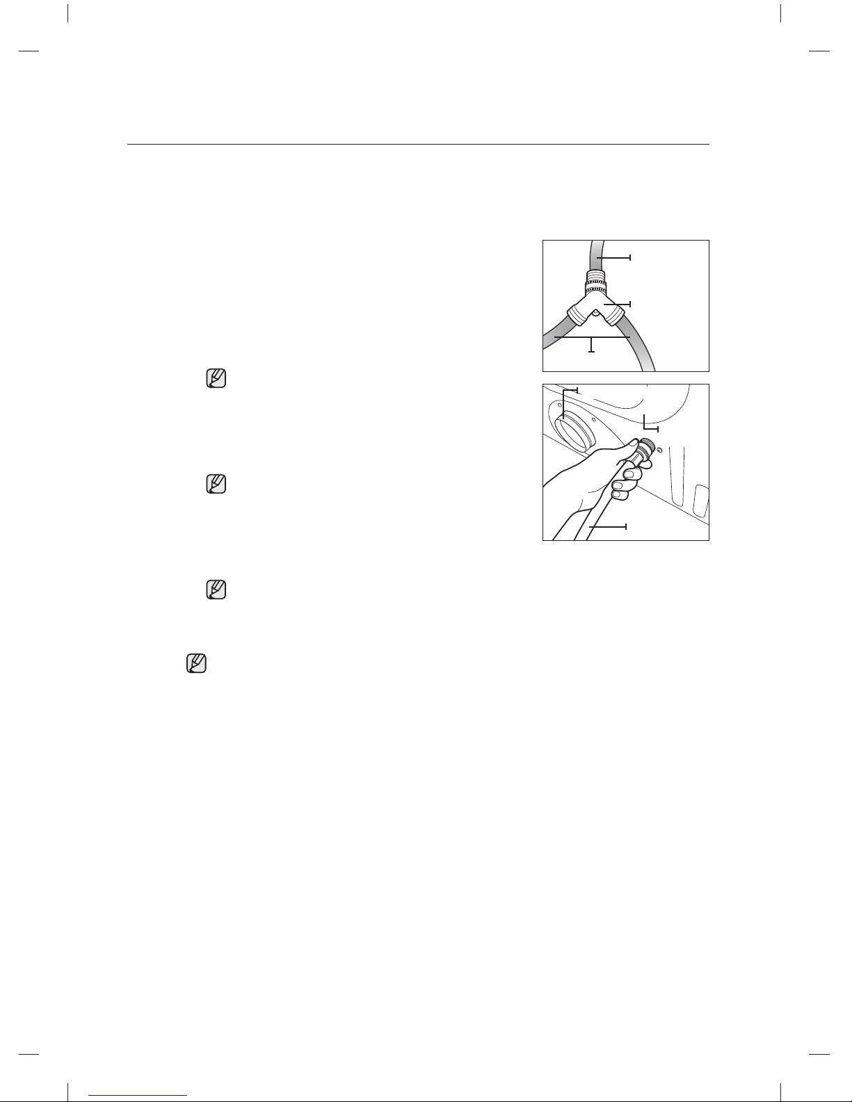
Method 2
The dryer must be connected to the cold water faucet using the new inlet hoses. Do not use old
hoses.
1. If the “Y” connector cannot be attached directly to the cold
water faucet, the short hose must be used.
2. Turn the cold water faucet o .
3. Attach the short inlet hose to the cold water faucet.
Screw on the coupling by hand until it is seated on the
faucet.
4. Using the pliers, tighten the coupling with an additional twothirds turn.
Do not overtighten, as this may damage the coupling.
5. Attach the ‘Y” connector to the brass male end of the small
hose. Screw on the coupling by hand until it is seated on the
connector.
6. Using the pliers, tighten the coupling with an additional twothirds turn.
Do not overtighten, as this may damage the coupling.
7. Attach the angled end of long hoses to the fi ll valve at the
bottom of the dryer rear frame. Screw on the coupling by
hand until it is seated on the fi ll valve connector.
8. Using pliers, tighten the coupling with an additional twothirds turn.
Do not overtighten, as this may damage the coupling.
9. Attach the washer hose to the other side of the “Y”
connector. Screw on the hose coupling until it is tight. Using
pliers, tighten the coupling with an additional two thirds turn.
Do not overtighten. You can damage the coupling.
10. Check that the water faucets are on.
11. Check for leaks around the “Y” connector, faucets and
hoses.
Short hose
(Inlet to cold
water)
“Y” connector
Long hose
Duct Exhaust
Frame
(back)
Water Hose
DV455_02836F-08_EN.indd 20DV455_02836F-08_EN.indd 20 2013-12-12 5:11:552013-12-12 5:11:55
English - 21
02 INSTALLING YOUR DRYER
REPLACEMENT PARTS AND ACCESSORIES
If your dryer requires replacement parts or accessories, contact the dealer where you purchased your dryer
or the SAMSUNG customer care center at 1-800-SAMSUNG (726-7864).
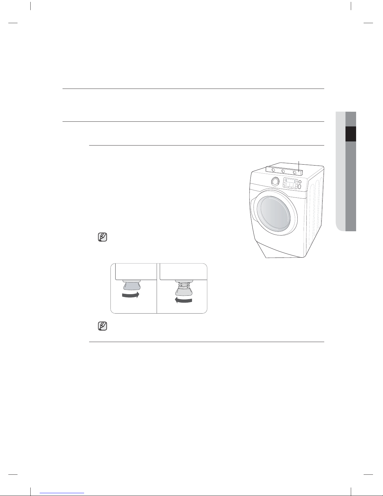
INSTALLATION
For the proper installation, we recommend that you hire a qualifi ed installer.
To install
1. Move your dryer to an appropriate location for the
installation. Consider installing the dryer and washer sideby-side, to allow access to the gas, electrical, and exhaust
connections. Place two of the carton cushion-tops on the
fl oor. Tip your dryer on its side so it lies across both cushiontops.
2. Set your dryer back in an upright position.
3. To ensure that the dryer provides the optimal drying
performance, it must be level. To minimize vibrations, noise,
and unwanted movement, the fl oor must be a perfectly level,
solid surface.
To set the dryer to the same height as the washer,
fully retract the leveling feet by turning them
counterclockwise, then loosen the legs by turning them
clockwise.
Retract fully Then loosen
Adjust the leveling feet only as much as necessary to
level the dryer. Extending the leveling feet more than
necessary can cause the dryer to vibrate.
Level
Leveling feet
4. Review the “Exhausting” section on page 15 before installing the exhaust system. Install the
ductwork from your dryer to the exhaust hood. The crimped end of the duct sections must
point away from your dryer.
DO NOT use sheet metal screws when assembling the ducting. These joints should be
taped.
Never use plastic fl exible exhaust material.
Tip for tight installations: install a section of the exhaust system onto your dryer before putting
it in place.
Use duct tape to secure this section to your dryer, but do not cover the ventilation slots at
the back of the unit in dryer cabinet.
DV455_02836F-08_EN.indd 21DV455_02836F-08_EN.indd 21 2013-12-12 5:11:552013-12-12 5:11:55
English - 22
Installing your dryer
5. Review the “Electrical requirements” section on page 17.
BEFORE OPERATING OR TESTING, follow the grounding instructions in the “Grounding”
section on page 17.
U.S. MODELS:
RISK OF ELECTRIC SHOCK - All U.S. models are produced for a 3-WIRE SYSTEM
CONNECTION.
The dryer frame is grounded to the neutral conductor at the terminal block.
A 4-WIRE SYSTEM CONNECTION is required for new or remodeled construction,
mobile homes, or if local codes do not permit grounding through neutral. If the 4-wire
system is used, the dryer frame cannot be grounded to the neutral conductor at
the terminal block. Refer to the following instructions for 3 and 4-WIRE SYSTEM
CONNECTIONS.
Remove the terminal block cover plate.
Insert the power cord with a UL-listed strain relief through the hole provided in the cabinet
near the terminal block.
A strain relief must be used.
Do not loosen the nuts already installed on the terminal block. Be sure they are tight.
Use a 3/8” (1 cm) deep well socket.
6. Review the “Gas requirements” section on page 16. Remove the pipe thread protective
cap. Apply a pipe joint compound or about 1 1/2 wraps of Tefl on tape over all threaded
connections.
The pipe joint compound must be resistant to the actions of any liquefi ed petroleum
gas.
Connect the gas supply to your dryer. An additional fi tting is required to connect the 3/4” (1.9
cm) female thread end of a fl exible connector to the 3/8” (1 cm) male threaded end on the
dryer.
Securely tighten the gas line fi tting over the threads.
Turn on the gas supply.
Check all gas connections for leaks using a soap solution.
If bubbles appear, tighten the connections and recheck. DO NOT use an open fl ame to
check for gas leaks.
WARNING
DV455_02836F-08_EN.indd 22DV455_02836F-08_EN.indd 22 2013-12-12 5:11:552013-12-12 5:11:55
English - 23
02 INSTALLING YOUR DRYER
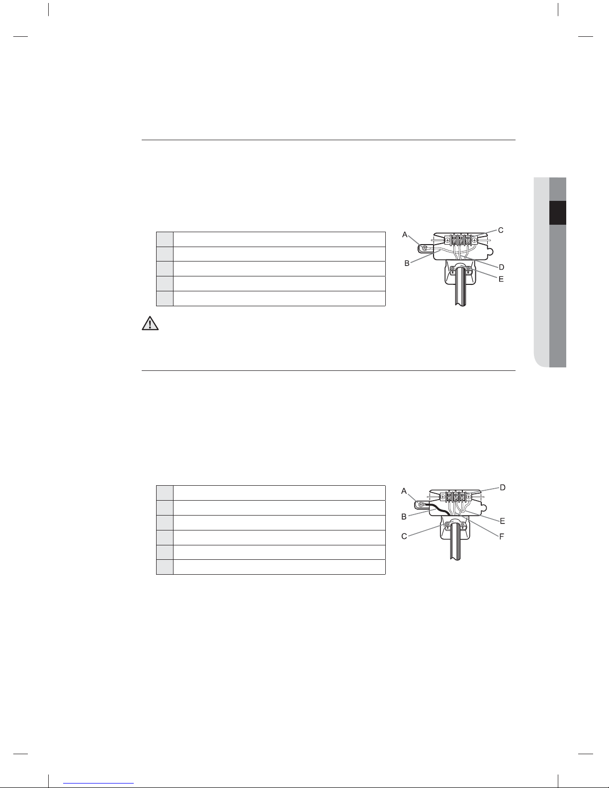
3-WIRE system connections
1. Loosen or remove the center terminal block screw.
2. Connect the neutral wire (white or center wire) of the power cord to the center, silver-colored
terminal screw of the terminal block. Tighten the screw.
3. Connect the other wires to the outer terminal block screws. Tighten the screws.
4. Tighten the strain relief screws.
5. Insert the tab of the terminal block cover into your dryer’s rear panel slot.
6. Secure the cover with a hold-down screw.
1 External ground connector
2 Neutral grounding wire (green/yellow)
3 Center silver-colored terminal block screw
4 Neutral wire (white or center wire)
5 3/4” (1.9 cm) UL-listed strain relief
If converting from a 4-wire electrical system to a 3-wire, the ground strap must be
reconnected to the terminal block support to ground the dryer frame to the neutral
conductor.
4-WIRE system connections
1. Remove the center terminal block screw.
2. Connect the ground wire (green or unwrapped) of the power cord to the external ground
conductor screw.
3. Connect the neutral wire (white or center wire) of the power cord and the appliance ground
wire (green with yellow stripes) under the central screw of the terminal block.
4. Connect the other wires to the outer terminal block screws. Tighten the screws.
5. Tighten the strain relief screws.
6. Insert the tab of the terminal block cover into your dryer’s rear panel slot.
7. Secure the cover with a hold-down screw.
1 External ground connector
2 Green or bare copper wire of the power cord
3 3/4 in. (1.9 cm) UL-listed strain relief
4 Center silver-colored terminal block screw
5 Grounding wire (green/yellow)
6 Neutral wire (white or center wire)
8. With a level, check your dryer and make the necessary adjustments to the leveling legs.
9. At this time, make sure all gas connections (on gas models), exhaust and electrical
connections are complete. Plug in your dryer, and check its operation by using the checklist
below.
10. (GAS MODELS ONLY)
The burner may not ignite initially due to air in the gas line. Allowing your dryer to operate on
a heat setting will purge the line. If the gas does not ignite within 5 minutes, turn your dryer
o and wait 5 minutes. Be sure the gas supply to your dryer has been turned on. In order to
confi rm the gas ignition, check the exhaust for heat.
WARNING
DV455_02836F-08_EN.indd 23DV455_02836F-08_EN.indd 23 2013-12-12 5:11:552013-12-12 5:11:55

English - 24
Installing your dryer
FINAL INSTALLATION CHECKLIST
• the dryer is plugged into an electrical outlet and is properly grounded.
• The exhaust ductwork is hooked up and the joints are taped.
• A plastic fl exible duct is NOT used.
• Use rigid or sti -walled fl exible metal vent material.
• The dryer is level and is sitting fi rmly on the fl oor.
• Gas models – the gas is turned on with no gas leaks.
• Start your dryer to confi rm that it runs, heats, and shuts o .
DRYER EXHAUST TIPS
A plastic or non-metal fl exible duct presents a potential fi re hazard.
1. Make sure your dryer is installed properly so it exhausts air
easily.
Wall
Duct
Exhaust
Dryer
2. Use a 4” diameter rigid metal duct. Tape all joints, including
at the dryer. Never use lint-trapping screws.
Duct
Tape
4”
3. Keep ducts as straight as possible.
4. Clean all old ducts before installing your new dryer. Be sure
the vent fl ap opens and closes freely. Inspect and clean the
exhaust system annually.
Don’t let a poor exhaust system slow the drying process by:
• Restricting your
dryer with a poor
exhaust system.
• Using a plastic, thin
foil, or non-metal
fl exible duct.
• Unnecessarily using
long ducts that have
many elbows.
• Allowing dented or
clogged ducts and
vent.
WARNING
DV455_02836F-08_EN.indd 24DV455_02836F-08_EN.indd 24 2013-12-12 5:11:562013-12-12 5:11:56
English - 25
02 INSTALLING YOUR DRYER
DOOR REVERSAL
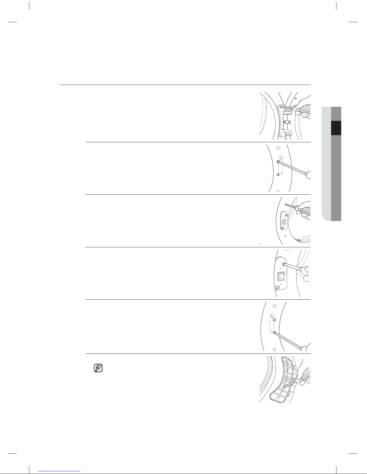
1. Unplug the power cord.
2. Remove two door hinge screws.
3. Lift the door and remove it.
4. Remove two screws from the frame front.
5. Remove the two screws from the opposite side of the door
hinge.
6. Remove the two screws from the holder lever.
7. Reassemble the two screws on the inside holes.
8. Remove a screw from the door hinge.
The screw is for pre-fi xing the door to the frame front.
DV455_02836F-08_EN.indd 25DV455_02836F-08_EN.indd 25 2013-12-12 5:11:562013-12-12 5:11:56
English - 26
Installing your dryer
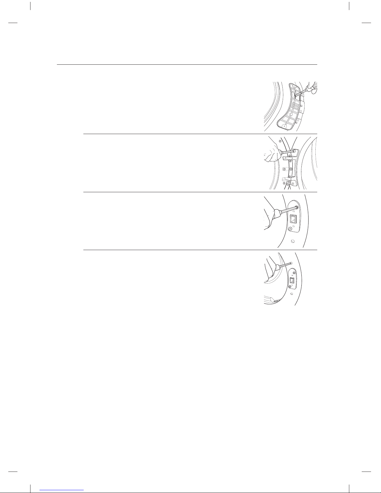
9. Reassemble the screw in the other hole.
10. Place the door on the other side and reattach it to the dryer.
11. Reattach the holder lever.
12. Reattach the screws in the remaining holes.
DV455_02836F-08_EN.indd 26DV455_02836F-08_EN.indd 26 2013-12-12 5:11:562013-12-12 5:11:56
English - 27
03 OPERATING INSTRUCTIONS, TIPS
Operating instructions, tips
To reduce the risk of fi re, electric shock, or injury to persons,read the IMPORTANT SAFETY
INSTRUCTIONS before operating this appliance.
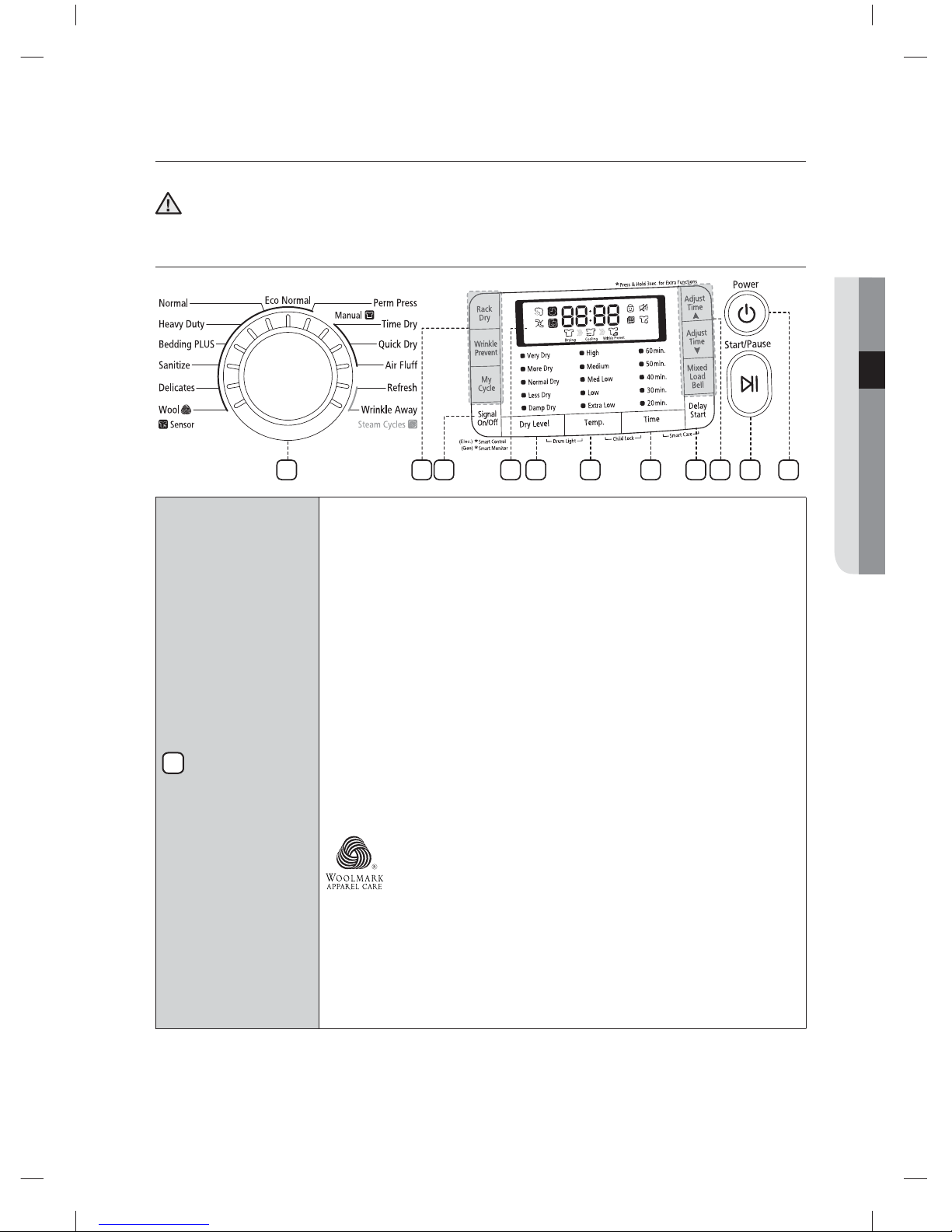
OVERVIEW OF THE CONTROL PANEL
1
Cycle Selector
To select a cycle, rotate the Cycle Selector dial to the desired cycle.
The indicator light by the cycle name will illuminate. The Wool, Delicates,
Sanitize, Bedding PLUS, Heavy Duty, Normal, Eco Normal and Perm Press
cycles are Sensor Dry cycles.
Sensor Dry automatically senses the moisture in the load and shuts the dryer
o when the selected dryness level (very dry to damp dry) is reached.
Eco Normal - This cycle reduces energy usage by up to 15% compared
to the Normal Dry cycle. It adjusts the cycle time and temperature for
increased e ciency.
Normal - Use this cycle to dry loads such as cotton, underwear, and linen.
Heavy Duty - Use this cycle to get high heat for heavy fabrics such as jeans,
corduroys, or work clothes.
Perm Press - Dry wrinkle-free cottons, synthetic fabrics, knits, and permanent
press fabrics automatically.
Bedding PLUS - For bulky items such as blankets, sheets, and comforters.
Delicates - The Delicates cycle is designed to dry heat-sensitive items at a
low drying temperature.
Wool - For machine washable and tumble dryable wool only.
Load should be under 3 pounds. The Wool cycle of this machine
has been approved by Woolmark company for Total-Easy-Care
Wool products, M0913(DV455E*) and M1007(DV455G*).
Sanitize - Sanitize garments by infusing high temperature heat deep into
the fabric during the drying cycle. Use this course to keep your bedding and
curtains clean through sanitization.
Time Dry - Time Dry allows you to select the desired cycle time in minutes.
Turn the Cycle Selector dial to Time Dry, then press the Adjust Time up arrow
to set the drying time. Press the arrow repeatedly to scroll through the time
settings.
WARNING
36 4 5 7
9
1
108
8 2
DV455_02836F-08_EN.indd Sec3:27DV455_02836F-08_EN.indd Sec3:27 2013-12-12 5:11:562013-12-12 5:11:56
English - 28
Operating instructions, tips
Quick Dry - Provides a 30 minutes drying cycle.
Air Flu - The Air Flu cycle tumbles the load in room temperature air.
Refresh - This cycle is best for smoothing out wrinkles and reducing odors
from loads consisting of one to four dry items. In this cycle a small amount
of water is sprayed into the dryer drum after several minutes of tumbling with
heat.
Wrinkle Away - The Wrinkle Away cycle removes wrinkles from clothes stored
in closets, etc. It provides wrinkle release via optimized steam care. You can
change the drying time.(Minimum time : 20 minutes) *For best results, load no
more than 3 items.
Overloading the dryer may not yield the same results.
2
LED Display
The display window shows the estimated time remaining in the cycle after the
Start/Pause button is pressed. The estimated time remaining may fl uctuate as
the cycle progresses.
The Drying light will illuminate and remain lit until the cycle is complete.
When your dryer is in the cool-down phase, the Cooling light will illuminate.
When your dryer is in the wrinkle prevent phase, the Wrinkle Prevent light will
illuminate.
When the cycle is complete, “End” will appear in the display panel until the
dryer door is opened or the Power button is pushed.
If your dryer is paused during a cycle, the indicator lights will blink until the
Start/ Pause button is pressed.
3
Dry Level
Selection Button
To select the dry level in the Normal, Heavy Duty, or other Sensor Dry cycles,
press the Dry Level button. An indicator light will illuminate next to the desired
dryness level.
Press the button repeatedly to scroll through the settings. Larger or bulkier
loads may require the Very Dry or More Dry setting for complete dryness.
The Less Dry setting is best suited for lightweight fabrics or for leaving some
moisture in the clothing at the end of the cycle. Damp Dry is designed to
partially dry items. Use for items that lay fl at or hang to dry.
4
Temp Selection
Button
To select the correct temperature for the load, press the Temp button. An
indicator light will illuminate next to the desired temperature. Press the button
repeatedly to scroll through the settings.
High – For sturdy cottons or those labeled Tumble Dry.
Medium – For permanent press, synthetics, lightweight cottons, or items
labeled Tumble Dry Medium.
Med Low – For lower heat than Medium to dry synthetic or washable knit
fabrics.
Low – For heat sensitive items labeled Tumble Dry Low or Tumble Dry Warm.
Extra Low – Provides the lowest heated dry temperature possible.
5
Time Selection
Button
When using Manual Dry cycles, you can adjust the drying time by pressing the
Time selection button.
During the Sensor Dry cycle, the time light indicator is o because exact
drying times are determined by fl uctuating humidity levels.
DV455_02836F-08_EN.indd Sec3:28DV455_02836F-08_EN.indd Sec3:28 2013-12-12 5:11:572013-12-12 5:11:57
English - 29
03 OPERATING INSTRUCTIONS, TIPS
6
Signal Selection
Button
When the cycle is complete, a chime will sound.
If you selected the Wrinkle Prevent option, the chime will sound intermittently.
Adjust the volume of the chime or turn it o by pressing the Signal button.
Press the button repeatedly to scroll through the choices.
7
Delay Start
Button
Any cycle can be delayed for up to 24 hours in one-hour increments.
Displayed hour indicates the time at which the cycle will be started. (Refer to
the “Delay Start” section on page 30.)
8
Select Cycle
Option
Adjust Time – Time can be added or subtracted from the automatically set
times in the Manual Dry cycles (Time Dry, Quick Dry, or Air Flu cycles) and
Wrinkle Away cycle.
To add or subtract time from the cycle, press the Adjust Time arrow pad up or
down until the desired time is displayed.
Wrinkle Prevent -Wrinkle Prevent provides approximately 180 minutes
of intermittent tumbling in unheated air at the end of the cycle to reduce
wrinkling. Press the Wrinkle Prevent button to activate this feature.
The indicator light above the pad will illuminate when Wrinkle Prevent is
selected.
The load is dry, and can be removed at any time during the Wrinkle Prevent
cycle.
My Cycle – Choose your favorite cycle including cycle, temp, dry level option,
etc. (Refer to the “My cycle” section on page 31.)
Rack Dry – Rack Dry is available in the Time Dry cycle. Temperature will be
set to Extra Low only. (Refer to the “Rack Dry” section on page 32.)
Mixed Load Bell - Mixed load bell - The mixed load bell that notifi es you when
the average dry level in a load is damp dry (80 % dried). This lets you take
garments that you don’t want fully dried or that dry quickly out of the dryer
early while letting others continue to dry. You can select this function in all
Sensor Dry cycles except Wool, Sanitize. The dry level selections are limited to
Normal Dry, More Dry, and Very Dry.
9
Start/Pause
selection button
Press to pause and restart programs.
10
Power button
Press once to turn your dryer on. Press again to turn it o . If your dryer is left
on for more than 10 minutes without any buttons being touched, the power
automatically turns o .
DV455_02836F-08_EN.indd Sec3:29DV455_02836F-08_EN.indd Sec3:29 2013-12-12 5:11:572013-12-12 5:11:57
English - 30
Operating instructions, tips
Child lock
Prevents children from playing with your dryer.
Setting/Releasing
To turn Child Lock on or o , press both the Temp. and Time buttons simultaneously for 3
seconds.
Child Lock Details
1. You can turn Child Lock on while your dryer is running.
2. Once you set the Child Lock function, no button, except for the Power button, will respond
until you turn o the Child Lock function.
3. The “Child Lock
” indicator will be lit.
• If the dryer is powered on again, the Child Lock function stays on.
• To turn o Child Lock, follow the instructions above.
When other buttons, except for the Power button, do not respond, check the Child Lock
indicator. If Child Lock is on, follow the instructions above to turn Child Lock o .
Delay Start
You can set the dryer to start your course automatically at a later time by choosing a delay time.
The hour displayed indicates the time at which the course will be started.
1. Set your drying course.
2. Press the Delay Start button repeatedly until the delay time is set.
3. Press the Start/Pause button. The “Delay Start
” indicator will be lit, and the clock will
begin counting down until it reaches the set time.
4. To cancel a Delay Start function, press the Power button and then turn the dryer on again.
Drum Light
Lights the dryer drum while the dryer is running.
Turning On and O
To turn on or turn o the Drum Light, press both the Dry Level and Temp. buttons
simultaneously.
You can turn the Drum Light on and o while your dryer is running and when it is stopped.
If you do not turn the Drum Light o 5 minutes after turning it on, the Drum Light is
automatically turned o .
DV455_02836F-08_EN.indd Sec3:30DV455_02836F-08_EN.indd Sec3:30 2013-12-12 5:11:572013-12-12 5:11:57
 Loading...