

Samsung DSR 9500A Instructions For Use Manual
DIGIT AL SATELLITE RECEIVER
FTA, CI, EM VIA, VIA CI
GB
DSR 9500A
Instructions foruse
“REV 1.0”
DSR 9500A FT A, CI, EM VIA, VIA CI
GB
GB-1
SAFETY INSTRUCTIONS
This STB has been manufactured to satisfy international safety standards.
Please read the following recommended safety precautions carefully.
MAINS SUPPLY: AC 100-240V ~, 50/60Hz
OVERLOADING: Do not overload wall outlets, extension cords or adapters
as this can result in fire or electrical shock.
LIQUIDS: Keep liquids away from the STB.
CLEANING: Before cleaning, disconnect the STB from the wall socket.
Use a cloth lightly dampened with water(no solvents) to
clean the exterior.
VENTILATION: Do not block the STB ventilation holes. Ensure that free airflow
is maintained around the STB. Never store the STB where it is
exposed to direct sunlight or near heating euipment e.g. a
radiator.
Never stack other electronic equipment on top of the STB.
Place the STB at least 30mm from the wall.
ATTACHMENTS: Do not use any attachment that is not recommended by the
manufacturer; it may cause a hazard or damage the equipment.
CONNECTION TO THE SATELLITE DISH LNB:
The LNB connector cable has voltage in its center core. It is
therefore recommended that the STB be disconnected from
the mains power before connecting or disconnecting this cable.
FAILURE TO DO SO COULD DAMAGE THE LNB.
SERVICING: Do not attempt to service this product yourself.
Any attempt to do so will make the warranty invalid.
Refer all servicing to a qualified service agent.
LIGHTNING: If the STB is installed in an area subject to intense lightning
activity, protection devices for the STB mains connector and
modem telephone line are essential.
The individual manufacturer’s instruction for safeguarding other
equipment, such as TV set, Hi-Fi, etc., connected to the STB must
also be followed during lightning storms.
GROUNDING: The ground of the LNB cable must be directly connected to the
system ground for the satellite dish.
The grounding system must comply with local regulations
NNoottee : Dispose the used batteries at designated place for environment protection

GB-2
DIGITAL SATELLITE RECEIVER
DSR 9500A FT A, CI, EM VIA, VIA CI
GB
GB-3
1. USER SECTION
4000 PROGRAMMABLE CHANNELS
SOFTWARE DOWNLOAD VIA SATELLITE & PC
ADVANCED ELECTRONIC PROGRAM GUIDE
MULTI LANGUAGE SUPPORTED FOR OSD
SUBTITLE & TELETEXT(OSD & VBI)SUPPORTED
WITH MULTI LANGUAGE
DiSEqC 1.2 SUPPORTED
FULL FUNCTION INFRARED REMOTE CONTROL UNIT
7 SEGMENT LED DISPLAY
AUTO AND MANUAL SCAN FACILITY
CHANNEL ORGANIZING(PROGRAMMABLE)
SCARTS & RCA OUTPUT
LOW POWER CONSUMPTION
9 FAVORITE LISTS
AUTO UPDATED EPG
PASS LOOP FOR RGB SIGNAL
2. TUNER SECTION
950~2150 MHz WIDE BAND TUNER
IF OUTPUT WITH DC PASS LOOP FOR ANALOG RECEIVER
SUPPORTING DiSEqC 1.2 VERSION
13V/18V SWITCHING
22KHz CONTINUOUS TONE CONTROL
3. VIDEO SECTION
DVB-S COMPLIANT
MPEG-2 VIDEO(MP@ML)
2~45 MS/s SYMBOL RATE
COMPATIBLE FOR BOTH SCPC/MCPC
SUPPORTS ASPECT RATIO 4:3(NORMAL) AND
16:9(WIDE SCREEN)
MODULATOR OUTPUT
4. AUDIO SECTION
MPEG 1 AUDIO LAYER I & II
MONO, DUAL, STEREO AND JOINT STEREO AUDIO MODE
32, 44.1 AND 48 kHz SAMPLING FREQUENCIES
VOLUME CONTROL AND MUTE FUNCTION THROUGH
REMOTE CONTROL UNIT
SPDIF DIGITAL AUDIO OUTPUT
GB-4
DIGITAL SATELLITE RECEIVER
DSR 9500A FT A, CI, EM VIA, VIA CI
GB
GB-5
7. INSERTING SMARTCARDS FOR VIACCESS SERVICES
In order to view a scrambled service, you need to have the appropriate
conditional Access Module and a valid Smartcard. This DSR 9500A has the
Viaccess CAS embedded to view Viaccess programmes.
NNoottee : Insert the Smartcard with the gold coloured chip facing downwards.
8. INSERTING COMMON INTERFACE CAM AND SMARTCARD
(For models DSR 9500A CI, DSR 9500A VIA CI)
The DSR 9500A supports Common Interface CAMs under DVB specification.
The CI CAMs include a built-in smart card reader.
● Insert the smart card into the CAM gently with the gold colored chip upwards
● Slide in the CAM gently inside the slot so that it sits in the socket tightly.
● Close the door.
● To remove the CAM push the button provided by the side of the CAM slot.
The CAM will be ejected from the socket.
NNoottee :
The following Common Interface CAMs are available now:
IRDETO, CONAX, CRYPTOWORKS, VIACCESS, NAGRAVISION,
SECA, Etc.
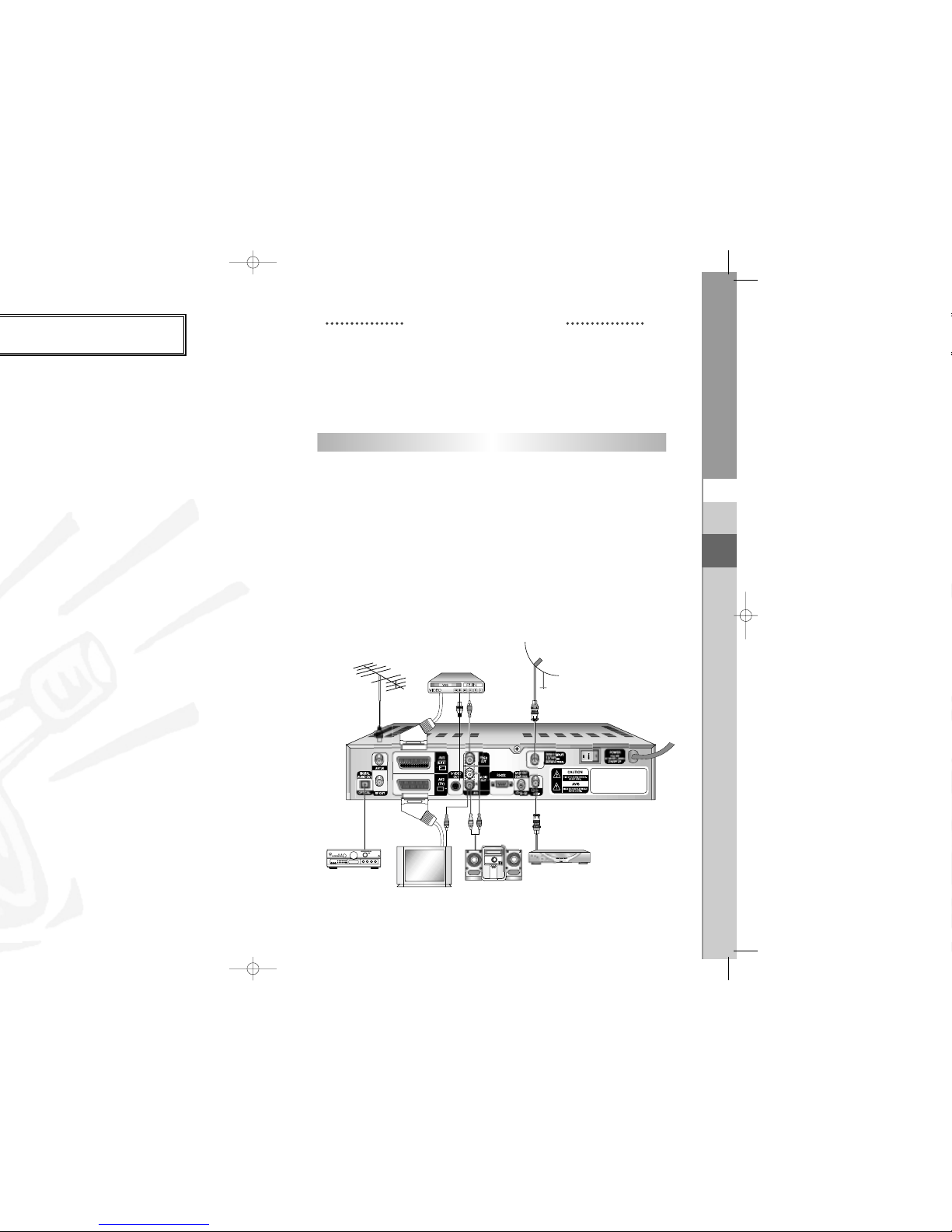
TV
" at the rear panel
SCART
cable, connect the
SCART
port on the TV.
LOOP
".
DSR 9500A
in standby,
Connecting Figure
CONNECTING YOUR "DSR 9500A"
GB-6
DIGITAL SATELLITE RECEIVER
DSR 9500A FT A, CI, EM VIA, VIA CI
GB
GB-7
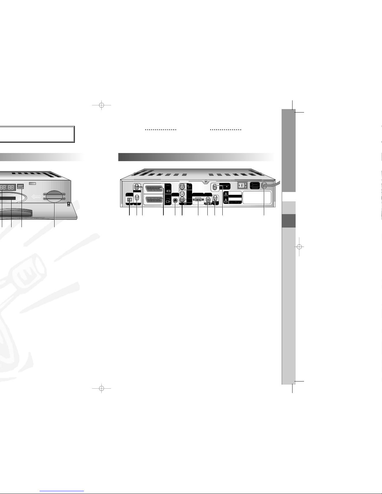
DESCRIPTION
1. AC MAINS This is to plug in the AC mains power cord.
The input AC voltage range is 100V to 240V, 50Hz/60Hz supply.
2. LNB This port is to connect the coaxial cable from LNB of your dish.
The IF input is provided through this port and the input frequency
range is 950-2150 MHz. Also the voltage switching 13V and
18V is passed through this port.
3. LOOP To enable the connection of an Analog receiver,
The receiver is provided with this ‘
LOOP
’ port.
4. RS 232 DATA PORT This is used to connect your receiver to a computer for reading
and loading data information.
5. S-VHS This is used to connect STB to your TV by using S-VHS cable.
6. SPDIF
Output for connection to a digital amplifier.
7. AV SCARTS This is used to connect to your TV & VCR or DVD player.
8. 0/12V This is used to connect to an external LNB switch.
9. VIDEO, AUDIO R/L These RCA connectors are used to connect any external
video and audio.
10. ANT.IN This is used to connect your local RF channels to
your TV through Loop.
11. TV This is used to connect to your TV via RF cable.
POWE
R
Pmax 4
0W
AC 100-240V ~, 50/60H
z
Fuse:250V T2
A
ANT.IN
(
EXT
)
RF OU
T
O
PTICA
L
DIGITA
L
AUDIO
OUT
S-VIDEO
OUT
DEO
AUDIO
OUT
0/12V OUT
50mA max.
DISH INP
UT
13/18V
500
mA max
.
CAUTION
RISK OF ELECTRIC SHODCK.
DO NOT OPEN.
RIQUE DE CHOC
LECTRIQU
E
NE PAS OUVRIR.
AVI
S
RS-232
L
AV2
TV
)
Rear Panel
6710 5 9 4
8
32
1
11
GB-8
DIGITAL SATELLITE RECEIVER
DSR 9500A FT A, CI, EM VIA, VIA CI
GB
GB-9
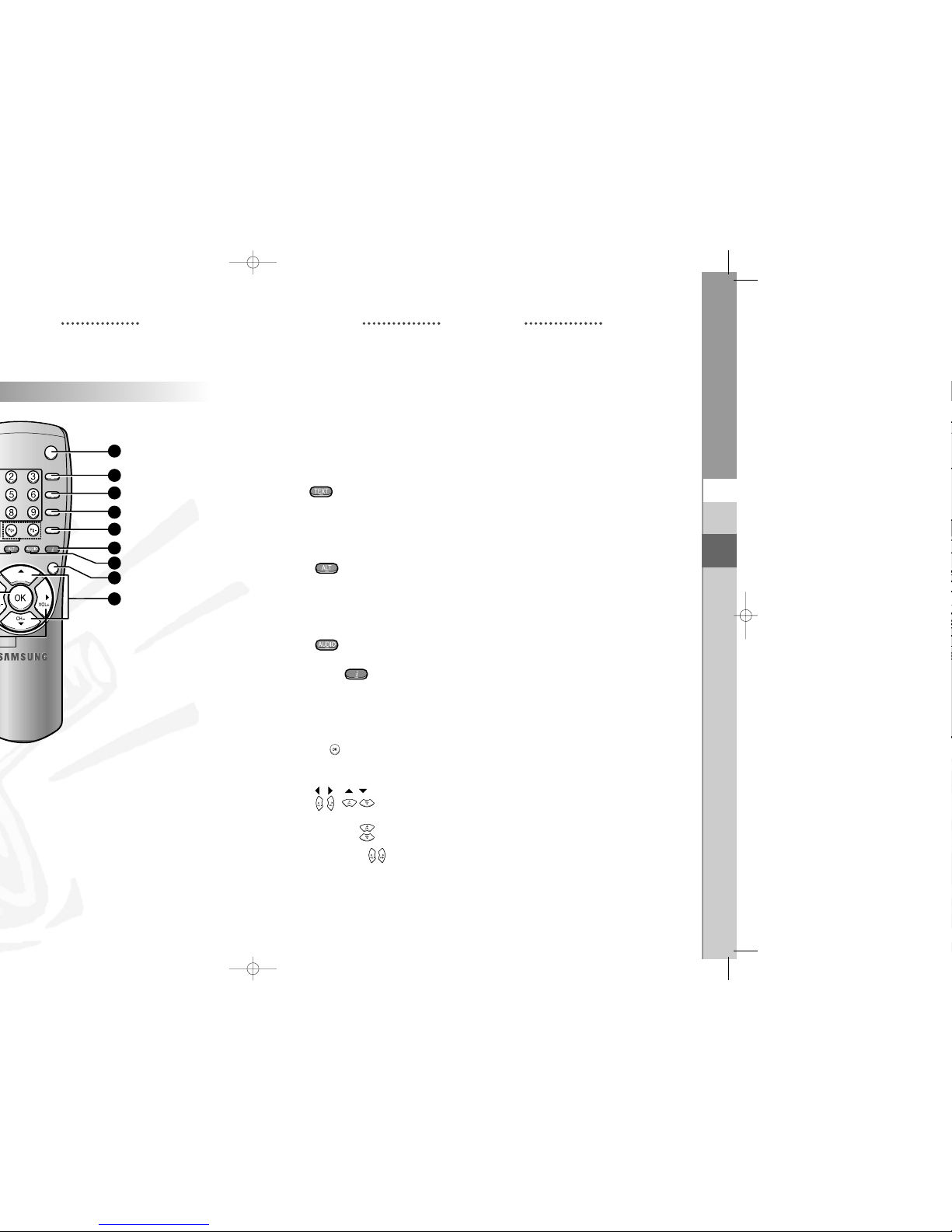
5. MUTE This key is used to toggle between normal & muted audio.
6. FAV Use the key to switch between favorite lists.
7. EPG Electronic Program Guide button displays the TV/Radio Program
guide.
8. LAST This key is used to call up directly whatever channel you were
watching list.
9. TEXT(GREEN) This key is used to select the subtitle mode.
()
This button functions same as the GREEN button on the menu.
Press once and subtitle appears. You can select the language you
want using the channel +/- keys.
Press twice and Teletext with OSD appears.
Press three times and Teletext with VBI appears.
10. ALT(YELLOW) This key is used to select the soundtrack list for the current service.
()
This button functions same as the YELLOW button on the menu.
Press once and sound track appears.
Press twice and video track appears.
The sound and video track services are not provided for every
channel and depend on the conditions the operator is in.
11. AUDIO(BLUE) This key is used to change the Audio to the left, right or both channels,
()
This button functions same as the BLUE button on the menu.
12. INFORMATION This key is used to display the programe information box in the screen.
(RED)
()
This button functions same as the RED button on the menu. Press
once and you can get simple information on the program. Press twice
and you can get detailed information on the channel in text box.
13. MENU This key is used to open up the menu or return to the previous menu.
14. EXIT This key is used to exit a menu or return to the previous menu.
15. OK( ) This key is used to enter and confirm any data to the receiver in the
menu system. This key is used to select the item. Press while viewing
TV and a list of channels is displayed.
16. , These keys are used to move the highlight bar for selecting
( , ) options on the menu, and this button is used to change channels
and increase or decrease the volume.
17. CH+/CH-( ) These keys are used to change channels.
18. VOL+/VOL-( ) These keys are used to increase or decrease the volume.
These keys are used to move up or down pages
on the channel list.
TV/RADIO
MUTE
FAV
EPG
LAST
EXIT
CH+
4
5
6
7
8
12
11
14
17
 Loading...