

Samsung IDH4400A, DH44ZAX, DH44ZA1A2, UDH4400G, DH44ZA1 Service Manual
...
DUCT TYPE AIR CONDITIONER
(Cool)
TYPE
ADH4400G
DH44ZA1(A2)
SERVICE
INDOOR UNIT
IDH4400A
DH44ZA1(A2)
OUTDOOR UNIT
UDH4400G
DH44ZAX
Manual
AIR CONDITIONER CONTENTS
1. Product Specifications
2. Installation
3. Operating Instructions
4. Troubleshooting
5. Disassembly and Reassembly
6. Exploded Views and Parts List
7. Schematic Diagrams
1. Product Specifications
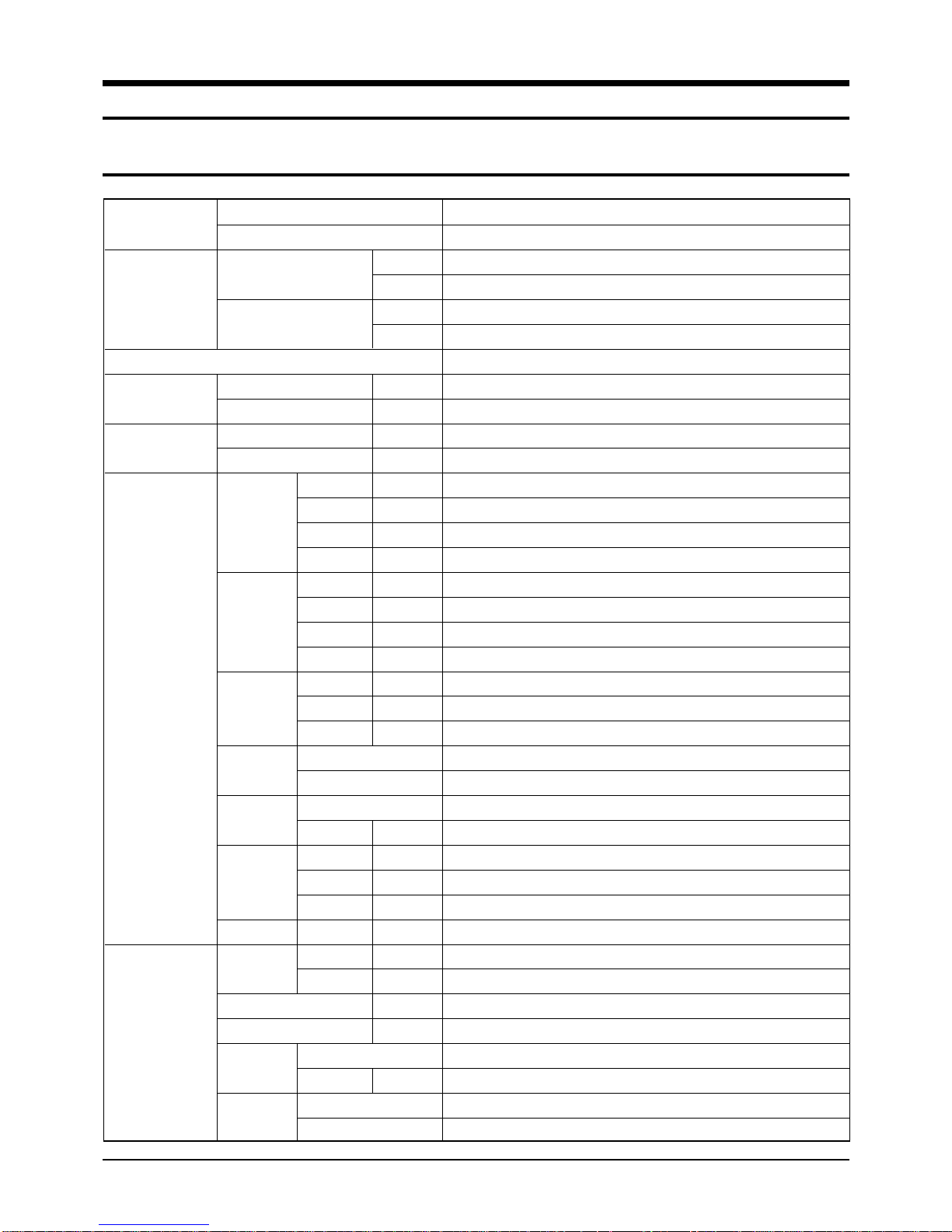
1-1 Table of Specifications
MODEL
Capacity
Power supply
Power input
Running current
Indoor
unit
Outdoor
unit
INDOOR UNIT
OUTDOOR UNIT
Cooling
Heating
Cooling
Heating
Cooling
Heating
Fan speed
(at 0mmAq)
Air
circulation
Noise Level
(Sound
pressure)
Heat
exchanger
row x stages x fin pitch
Fan
motor output
Dimensions
Weight
Fan speed
Air circulation (Hi)
Sound pressure level
Fan
motor output
Compressor
H.H
Hi
Med
Low
H.H
Hi
Med
Low
Hi
Med
Low
H
W
D
kg
Hi
Low
type
type
type
type
model
Btu/h
W
Btu/h
W
kW
kW
A
A
r.p.m
r.p.m
r.p.m
r.p.m
3
/min
m
3
/min
m
3
/min
m
3
/min
m
dB(A)
dB(A)
dB(A)
W
mm
mm
mm
Net/Gross
r.p.m.
r.p.m.
3
/min
m
dB(A)
W
IDH4400G / DH44ZA1(A2)
UDH4400G / DH44ZAX
45,000
13,200
54,900
16,100
3ø 380-415V~ 50Hz
4.8
5.3
8.5
9.2
940
880
850
790
36
34
32
30
49
48
47
Wave fin coil
3 x 14 x 1.7(900mm)
Siroco
211
390
1,110
650
70/78
900
500
90
65
propeller
114
scroll
ZR61KC-TFD
Samsung Electronics
1-1
Product Specifications
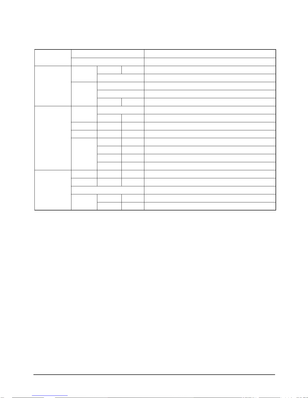
MODEL
Outdoor
unit
Condition
Piping
INDOOR UNIT
OUTDOOR UNIT
Compressor
motor output
Heat
exchanger
row x stages x fin pitch
face area
Refrigerant
(R22)Charge
Dimensions
(H x W x D)
Weight
Indoor unit
Cool(DB/WB)
Heat(DB/WB)
Outdoor unit
Cool(DB/WB)
Heat(DB/WB)
Pipe O.D.
size
Connection method
Between
Pipe length
kg
Liquid
Gas
Height
protection
type
control
Net/Gross
kW
2
m
g
mm
˚C
˚C
˚C
˚C
mm(inch)
mm(inch)
m
m
IDH4400G / DH44ZA1(A2)
UDH4400G / DH44ZAX
3.79
Internal
wave fin coil
2 x 48 x 1.7(935/915)
1.122
Capillary
4,000
1,240 x 930 x 385
123/133
27/19
20/15
35/24
7/6
9.52(3/8”)
19.05(3/4”)
Flare
Max. 25
Max. 50
Notice :
This model is tested under the external static pressure of 14mmAq
1-2
Samsung Electronics
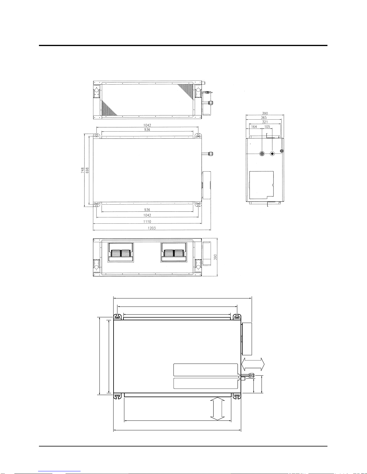
1-2 Dimensions
• Indoor unit
Samsung Electronics
650(Outer dimensions)
698(Space of suspension bolts)
1023
1042(Space of suspension bolts)
936 x 321(Dimension of outlet duct flange)
Pipe connection port
(Liquid pipe:ø9.52mm, Gas pipe:ø19.05mm)
Drain pipe connection port
(Out diameter:ø27.2mm)
936 x 321(Dimension of inlet duct flange)
1110(Outer Dimensions)
1200mm
Inspection area
Electrical
component box
Inspection area
1200mm
131
157
1-3
Product Specifications
;
;
;
;
;
;
;
;
;
;
;
;
;
;
;
;
;
;
;
;
;
;
;
;
;
;
;
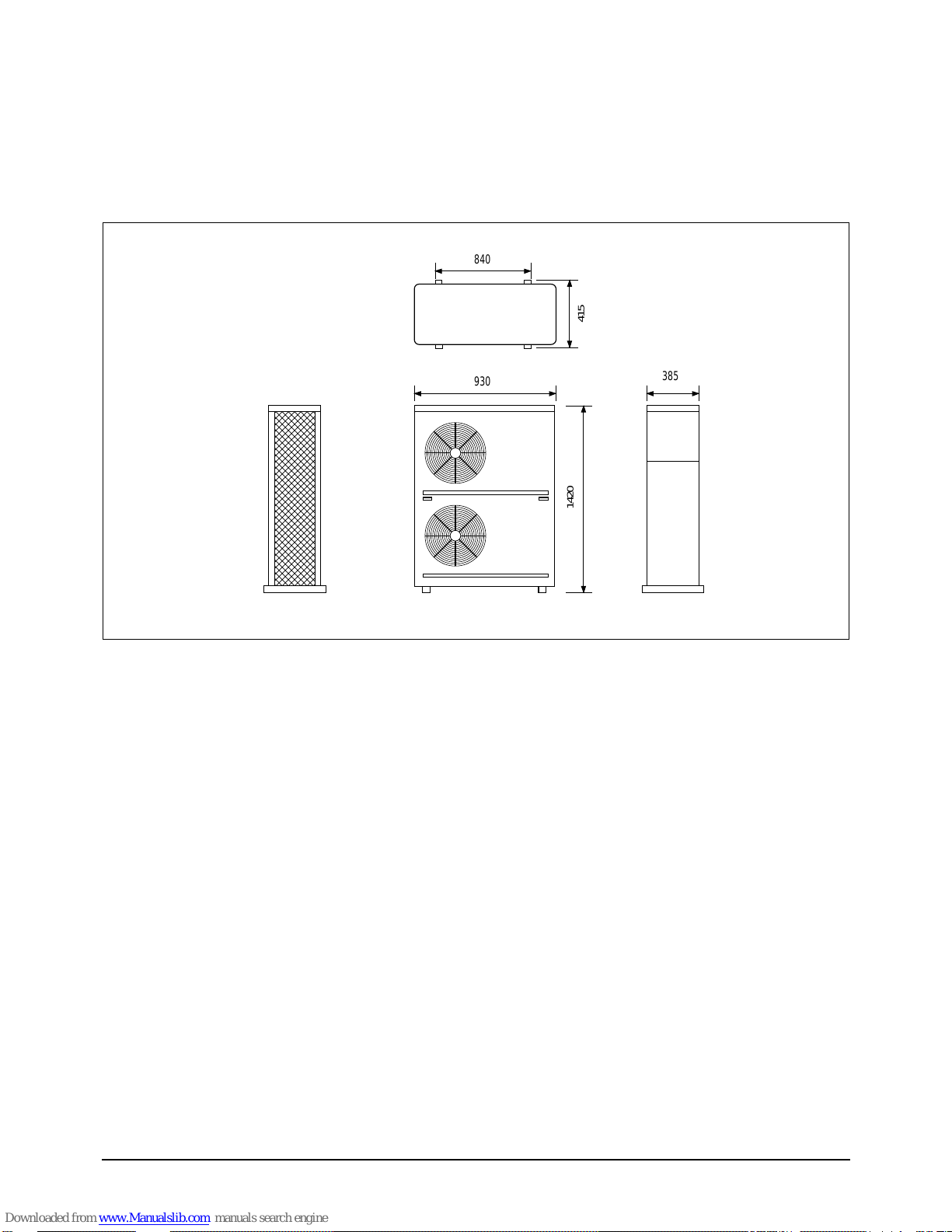
• Outdoor Unit
840
415
;;;;;
;;;;;
;;;;;
;;;;;
;;;;;
;;;;;
;;;;;
;;;;;
;;;;;
;;;;;
;;;;;
;;;;;
;;;;;
;;;;;
;;;;;
;;;;;
;;;;;
;;;;;
;;;;;
;;;;;
;;;;;
;;;;;
;;;;;
;;;;;
;;;;;
;;;;;
;;;;;
930
385
1420
1-4
Samsung Electronics
2. Installation
SW2
SW1
CN7
CN9
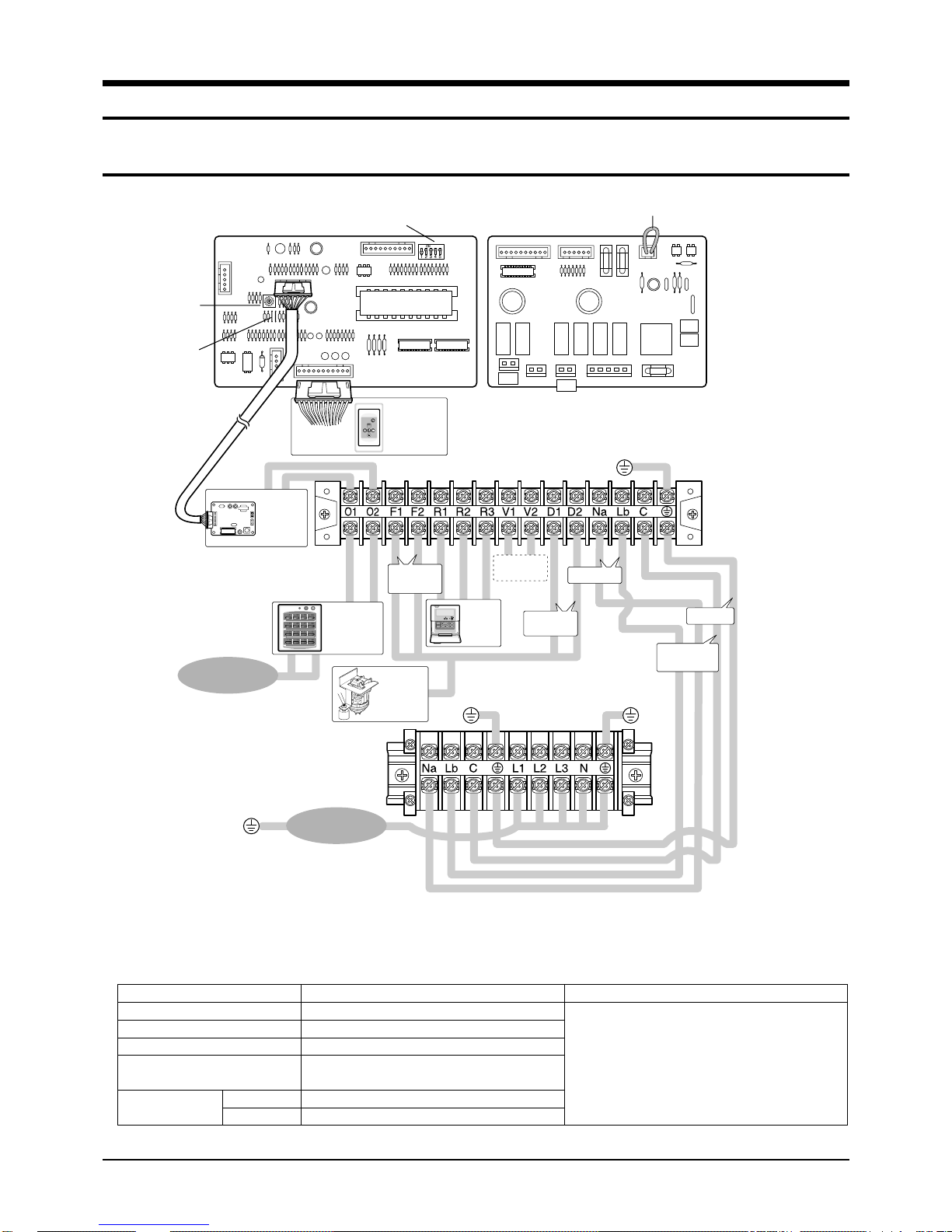
2-1 Wiring diagram
Rotary
Digital
Switch
Jumper
Wire
MAIN POWER
220-240V~,
MAIN PCB SUB PCB
DIP Switch
Receiver &
Display Unit
(Optional)
Indoor Unit
Transmitter
(Optional)
Ventilator
Wired
Remote
Controller
(Optional)
Motor
50Hz
Centralized
Controller
(Optional)
Float Switch
Float Switch
Drain Pump
(Optional)
Outdoor Unit
Drain Pump
CN20 Connector
Power
Earth
Communication
MAIN POWER
3ø, 380-415V~,
Cable Specifications
The following electrical characteristics must be respected.
MODEL
Power
Sub switch
Fuse
Min. size of electric Wires
from/to the indoor/outdoor unit
Size of electric
input wires
Samsung Electronics
20m or less
50m or less
50Hz
ADH4400G / DH44ZA1(A2)
3Ø, 380-415V~, 50Hz
H07RN-F, 4G, 1.25mm
H07RN-F, 3G, 2.5mm
H07RN-F, 3G, 4.0mm
30A
30A
Note
◆ The power cables are not
supplied with the air conditioner.
The user should purchase them separately.
2
2
2
◆ When connecting the cables to the
main power, you should connect each
cable(L1, L2 & L3) properly.
2-1
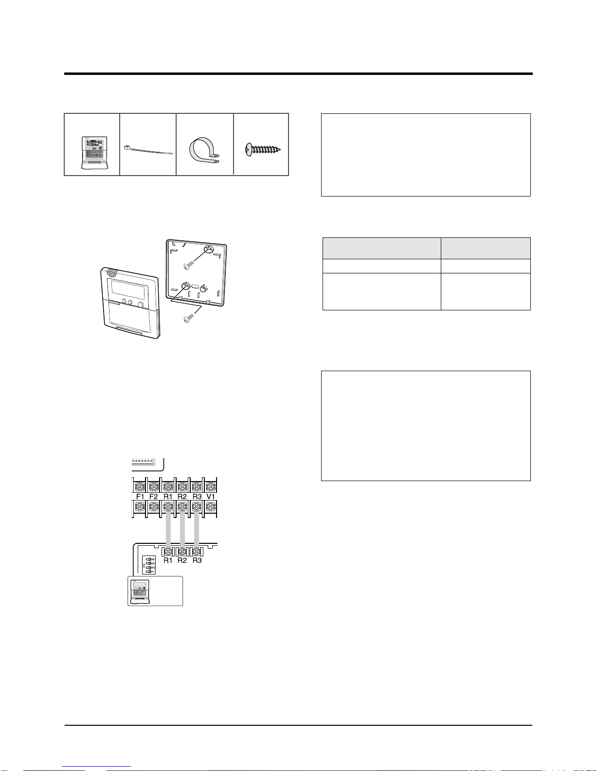
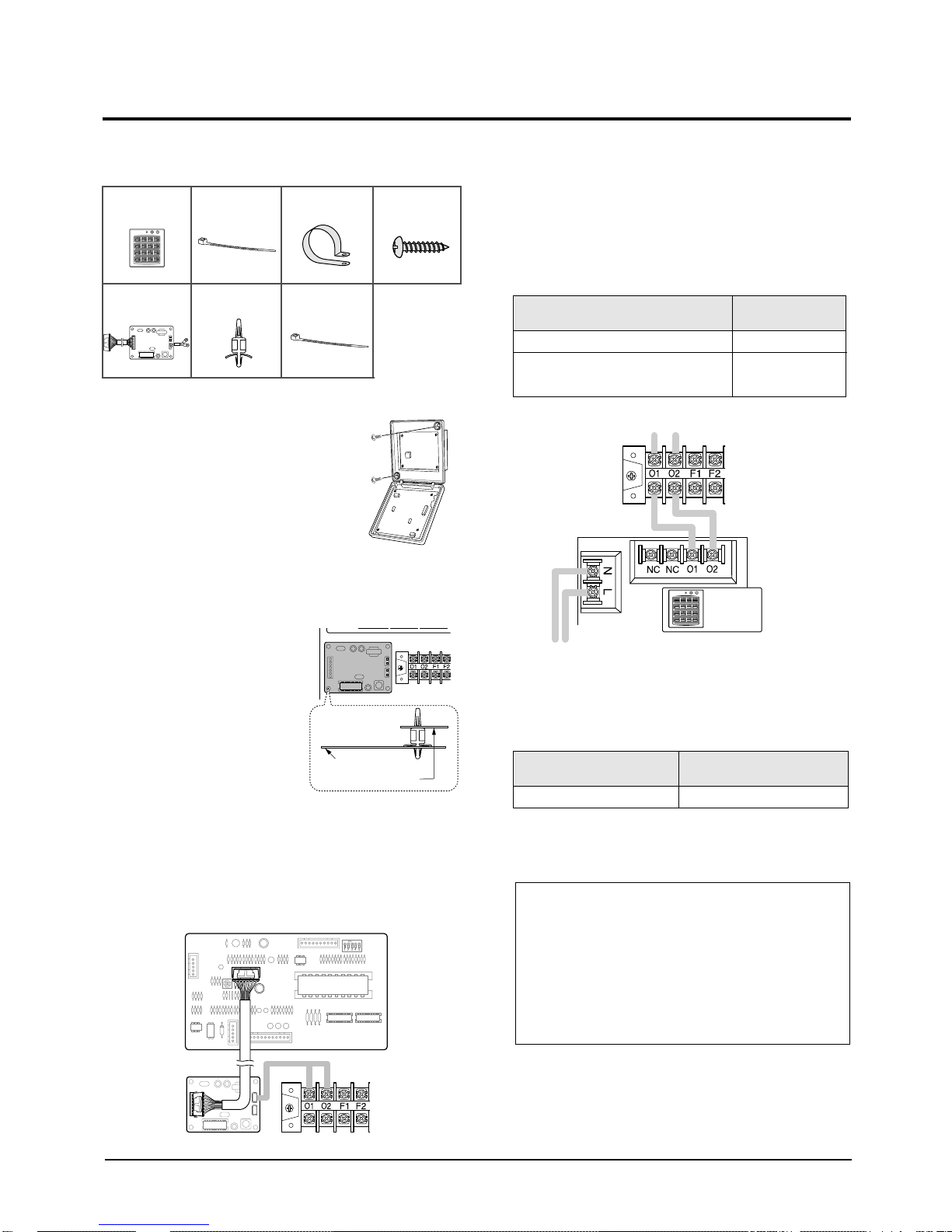
2-2 Wired Remote Controller Installation
Accessories
Wired Remote
Controller(1)
Cable-Tie(2) Cable Clamp(5) M4 X 16 Tapped
Screw(7)
1. Disassemble the wired remote controller by
using two grooves on the top of it.
2. Secure the rear cover of the wired remote
controller on the wall with two screws.
3. Connect the R1, R2 and R3 terminals in the
wired remote controller to the R1, R2 and R3
terminals on the electrical component box each.
Caution :
• Do Not keep the wired remote controller cables with a
220V cable because the remote controller cables have
low voltage.
• Do Not input 220V power to the R1, R2 and R3 in the
wired remote controller.
Note : Cable Specifications
Cable type
Size of cables
Max. length of electric wires from
the indoor unit to the wired remote
controller
Double-insulation, 3G
0.3mm2~0.75mm
100m
4. Reassemble the wired remote controller.
Caution :
• The optional kits must be installed by an installation
specialist.
• Before installing the optional kits, ensure that you have
turned off the main power.
• All optional kits cables should be installed according to
the national wiring rules and you must install them in the
wall not to be touched by users.
2
Wired
Remote
Controller
2-2
Samsung Electronics
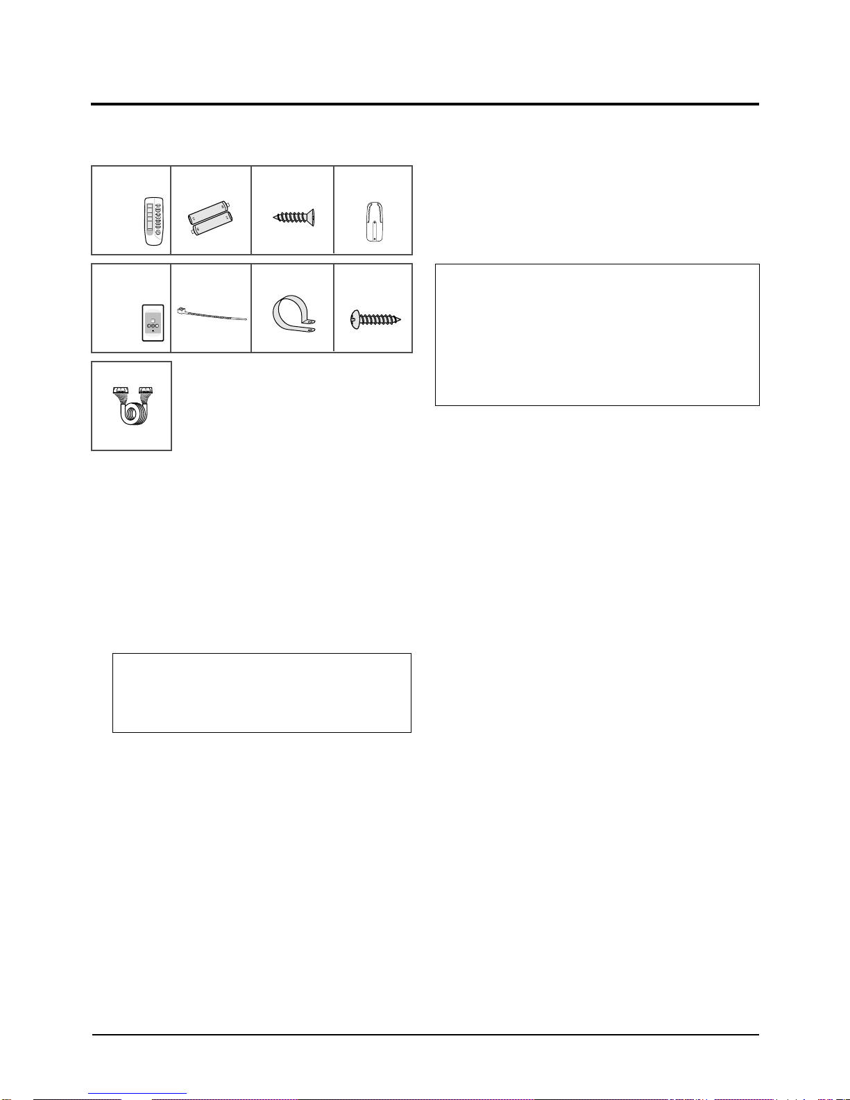
2-3 Wireless Remote Controller Installation
Accessories
Wireless Remote
Controller(1)
Receiver &
Display Unit(1)
Wire Kit
Length : 10m
1. Remove the receiver & display unit cover by
using the tab on the bottom of it.
2. Open the receiver & display unit.
Battery(2) M4 X 16 Tapped
Screw(2)
Cable-Tie(2) Cable Clamp(5) M4 X 16 Tapped
Remote Controller
Holder(1)
Screw(7)
4. Close the receiver & display unit.
5. Secure the receiver & display unit on the wall
with two screws.
6. Reassemble the receiver & display unit cover.
Caution :
•The optional kits must be installed by an installation specialist.
•Before installing the optional kits, ensure that you have turned
off the main power.
•All optional kits cables should be installed according to the
national wiring rules and you must install them in the wall not
to be touched by users.
3. Connect the end of the connector wire to the
receiver & display unit and connect the other
end of the wire to the electrical component box
as shown in figure.
Caution :
•Do NOT keep the receiver & display unit cables with a
220V cable because the remote controller cables have
low voltage.
Samsung Electronics
2-3
2-4 Centralized Controller Installation
Accessories
Centralized
Controller(1)
Transmitter(1) Spacer Support(4) Cable-Tie(2) M4 X 16 Tapped
1. Open the centralized controller
cover by using two grooves on
the top of it.
2. Secure the rear cover of the centralized
controller on the wall with two screws.
3. Secure the transmitter
with four spacer supports
into the electrical
component box.
Cable-Tie(2) Cable Clamp(5) M4 X 16 Tapped
Screw(7)
Screw(7)
5. Connect the O1 and O2 terminals of the
centralized controller to the O1 and O2
terminals on the electrical component box as
shown in figure.
Note : Cable Specifications
Cable type
Size of cables
Max. length of electric wires from the
indoor unit to the centralized controller
Double-insulation,
2G(Shield Cable)
0.75mm2~1.25mm
Centralized
Controller
6. Connect the power cables.
2
1km
Electrical component box
Transmitter
4. Connect the cable from the PCB and to the
transmitter.
And connect another cable from the O1, O2
terminals and to the transmitter as shown in
figure.
2-4
Note : Cable Specifications
Cable type
Size of cables 0.75mm2~1.25mm
Double-insulation, 2G
7. Reassemble the centralized controller.
Caution :
•The optional kits must be installed by an installation
specialist.
•Before installing the optional kits, ensure that you have
turned off the main power.
•All optional kits cables should be installed according to
the national wiring rules and you must install them in the
wall not to be touched by users.
Samsung Electronics
2
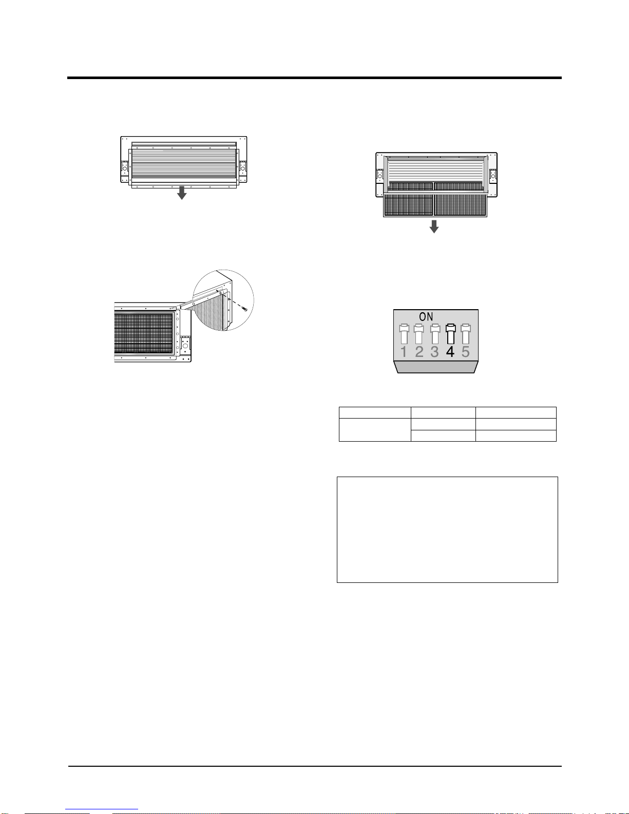
2-5 Air Filter Installation
1. Remove the air inlet duct flange.
2. Attach the air filter kit to the air inlet side of
indoor unit.
3. To clean the air filter, remove the fixing bracket
on the base of air filter kit, then pull out the
filter.
Note: Setting Up Filter Cleaning Cycle
• Adjust the DIP switch(SW2) in the main PCB to
the desired position referring the table below.
Switch No.
4
Switch Position
ON
OFF
Filter Cleaning Cycle
1,000 hours
2,000 hours
Caution :
•The optional kits must be installed by an installation
specialist.
•Before installing the optional kits, ensure that you have
turned off the main power.
•The optional air filter has to be cleaned only by an
authorized person or service agent.
Samsung Electronics
2-5
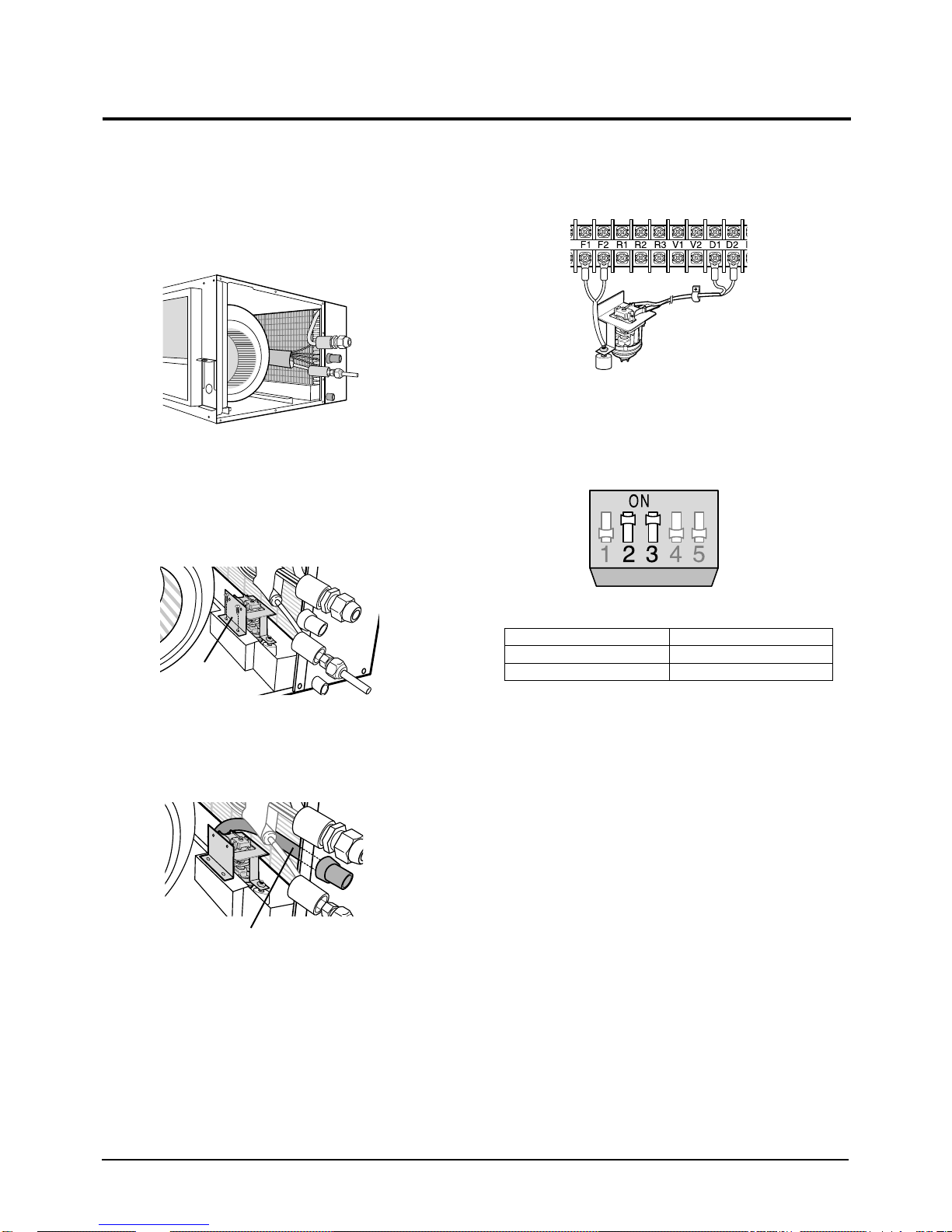
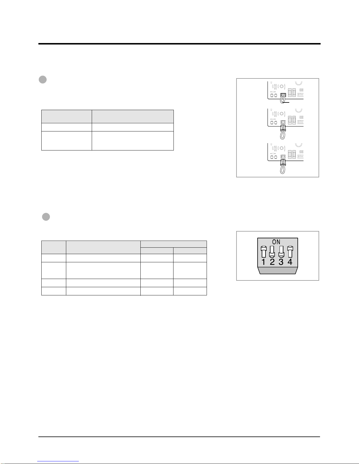
2-6 Drain Pump Installation
Care must be taken when installing the drain hose for
the indoor unit to ensure that any condensate water is
correctly drained outside.
1. Open the side of indoor unit.
2. Screw the drain pump with two screws.
Note : When installing the drain pump, leave a 7mm
space between the bottom of the drain pan and
the drain pump.
4. Connect the cable to the electrical component
box as shown in figure.
Drain pump
Float
switch
5. Adjust the DIP switch(SW2) on the main PCB
according to the table below.
Drain pump
3. Connect the drain hose to the drain socket.
Drain pump hose
Switch No.
2
3
Note : Wrap the drain tube outlet with an insulating
materials.
Switch Position
ON
ON
2-6
Samsung Electronics
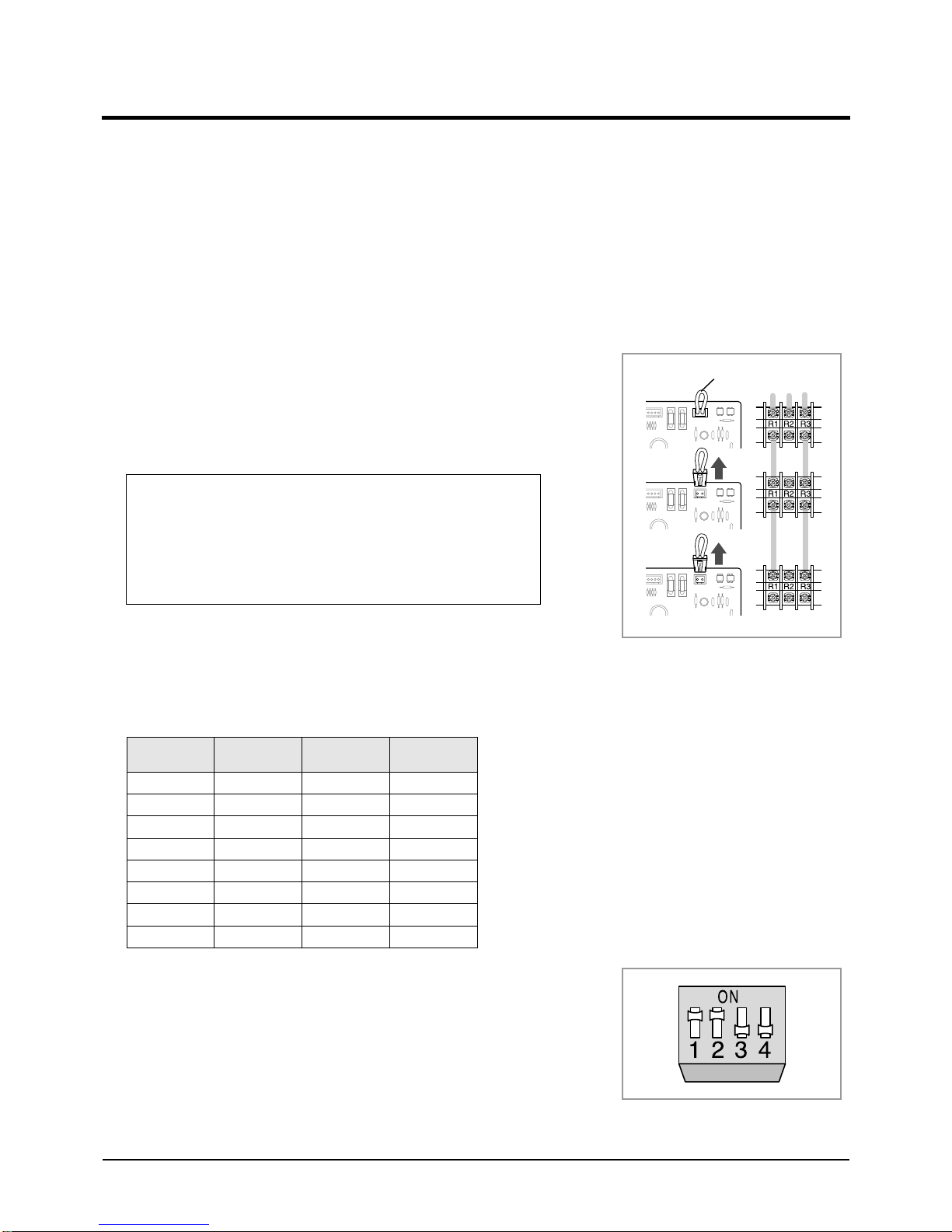
2-7 Group Control Installation
* You should adjust the option switches in the electrical component box or on the PCB of the wired remote controller.
* Before setting up the option switches, always make sure that you have turned off the main power.
* After adjusting the options, you should supply the power. Otherwise, the options will not be applied.
2-7-1. With Wired Remote Controller
A user can operate up to sixteen air conditioners by using the wired remote controller In this case, the air conditioner can
be controlled by only one wired remote controller connected to the indoor unit and cannot be controlled by the others.
1. Connect the R1, R2 and R3 terminals in the wired remote
controller to the R1, R2 and R3 terminals in any indoor unit
“A” each.
2. Connect the R1 and R3 terminals in the indoor unit “A” to the
R1 and R3 terminals in another indoor unit “B”.
Caution :
When connecting the cables, you must keep these :
• The R1 terminals must be connected to the R1s.
• The R3 terminals must be connected to the R3s.
• Do not connect the R2 terminals to anywhere.
• If you connect R2 terminals, the PCB will be damaged.
3. Connect the R1 and R3 terminals of “B” to any indoor unit
“C” and connect the others as the same way.
4. Remove the CN20 connectors on the sub PCBs except the unit
connected with remote controller(Adress “0”).
Switch No.
0
1
2
3
4
5
6
7
Number of
indoor unit(s)
One
Two
Three
Four
Five
Six
Seven
Eight
Switch No.
8
9
A
B
C
D
E
F
Number of
indoor unit(s)
Nine
Ten
Eleven
Twelve
Thirteen
Fourteen
Fifteen
Sixteen
Unit A
Unit B
Unit C
CN20
Connector
5. Remove the CN20 connectors on the sub PCBs except the unit
connected with remote controller(Address “0”).
6. Adjust the DIP switch No. 2 in the wired remote controller to
“ON” position.
Note : You cannot install the centralized controller when the wired
remote controller for a group has already been installed.
Samsung Electronics
2-7

Product Specifications
2-7-2. With Centralized Controller
A user can turn on/off up to sixteen air conditioners by using the centralized controller.
In this case, the user can turn on/off all air conditioners or a specific air conditioner connected with the centralized
controller. And each air conditioner can be controlled by its own remote controller(s) depending on the setting.
1. Connect the O1 and O2 terminals in the centralized controller to
the O1 and O2 terminals in the indoor unit “A”.
2. Connect the O1 and O2 terminals in the indoor unit “A” to the
O1 and O2 terminals in another indoor unit “B”.
3. Connect the O1 and O2 terminals of “B” to any indoor unit “C”
and connect the others as the same way.
4. Adjust the DIP switch(DS01) in the centralized controller to the
desired position referring to the table below.
Switch
Switch
Position
1234 Meaning
No.
OFF
OFF
OFF
OFF
OFF
OFF
OFF
OFF
ON
The air conditioner is operated by the controller
OFF
adjusted last among the wired remote controller,
wireless remote controller and centralized controller.
A user can use wired/wireless remote controller when
the centralized controller is switched on.
ON
And he/she cannot use the remote controller(s) when
the centralized controller is switched off.
The air conditioner(s) can be controlled by only the
OFF
centralized controller. The user cannot use the
wired/wireless remote controller in this case.
5. Adjust the rotary switch on the transmitter to the desired position
referring to the table on page 2-11.
Note : You cannot install the centralized controller when the wired remote
controller for a group has already been installed.
Centralized
Controller
Unit A Unit B Unit C
Centralized
Controller
2-8
Samsung Electronics

2-8 Setting Up Option Switches
IMPORTANT : Before setting up the option switches, always make sure that you have turned off the main power.
Main PCB in the Indoor Unit
Rotary Switch(SW1)
A user can operate up to sixteen air conditioners by using the wired remote
controller. Before controlling more than one air conditioner, you should
connect the air conditioner each other. And you must assign addresses to the
air conditioners. For further details on connecting air conditioners.
If the user would like to controller only one air conditioner, make sure that
the arrow is at “0” position.
Turn the arrow to the desired position referring to the table below.
Switch No.
0
1
2
3
4
5
6
7
Number of
indoor unit(s)
One
Two
Three
Four
Five
Six
Seven
Eight
Switch No.
8
9
A
B
C
D
E
F
Number of
indoor unit(s)
Nine
Ten
Eleven
Twelve
Thirteen
Fourteen
Fifteen
Sixteen
DIP Switch(SW2)
Adjust the switch to the desired position referring to the table below.
Switch
No.
1
2
3
4
5
Option Item
Ventilator Fan
Drain Pump
Float Switch
Filter Cleaning Cycle
Indoor Fan Motor Speed
Switch Position
ON OFF
Not installed
Installed
Installed
1,000 hours
Normal
Installed
Not installed
Not installed
2,000 hours
High speed
Not supplied
Optionally
supplied
Caution :
• If you do not adjust the switch when not installing the drain pump, "✳9" error
will occurs. If this happens, adjust the No.2 and No.3 switches to the "OFF"
position.
Note
Samsung Electronics
2-9
Setting Up Option Switches (Cont.)
Sub PCB in the Indoor Unit
CN20 Connector
Remove the CN20 connector in the sub PCB, if necessary, referring to the
table below. (This procedure is needed only when the user would like to
control a group by using the wired remote controller.)
Address Situation of the CN20 Connector
0
1 - F
Note : ◆ Up to 16 air conditioners can be controlled with one wired remote
controller.
Note : ◆ If the user does not want to control a group, do not remove the
CN20 Connector.
Connected
Removed
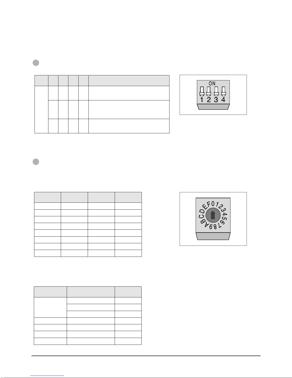
PCB in the wired remote controller
Dip Switch(DS01)
Adjust the DIP switch to the desired position referring to the table below.
Switch
No.
1
2
3
4
Option Item
Type of unit
Number of air conditioner(s) controlled
by the wired remote controller
Basic specification
Using wireless remote controller
Switch Position
ON OFF
Cooling only
Group
controlling
-
Can be used
Heat pump
One indoor unit
controlling
O
Cannot be used
Unit A
(Address 0)
Unit B
(Address 1)
Unit C
(Address 2)
CN20 Connector
2-10
Samsung Electronics
Centralized Controller
DIP Switch(DS01)
Adjust the DIP switch to the desired position referring to the table below.
Switch
Switch
Position
1234 Meaning
No.
OFF
OFF
OFF
OFF
OFF
OFF
OFF
OFF
ON
The air conditioner is operated by the controller
OFF
adjusted last among the wired remote controller,
wireless remote controller and centralized controller.
A user can use wired/wireless remote controller when
the centralized controller is switched on.
ON
And he/she cannot use the remote controller(s) when
the centralized controller is switched off.
The air conditioner(s) can be controlled by only the
OFF
centralized controller. The user cannot use the
wired/wireless remote controller in this case.
Note : You cannot install the centralized controller
when the wired remote controller for a group
has already been installed.
Transmitter
Rotary Switch(DS01)
A user can turn on/off up to sixteen air conditioners by using the centralized controller. To use the controller,
you must assign addresses to the air conditioners. For further details on connecting air conditioners.
If the user would like to controller only one air conditioner, make sure that the arrow is at “0” position.
Turn the arrow to the desired position referring to the table below.
Switch No.
0
1
2
3
4
5
6
7
Number of
indoor unit(s)
One
Two
Three
Four
Five
Six
Seven
Eight
Switch No.
8
9
A
B
C
D
E
F
Number of
indoor unit(s)
Nine
Ten
Eleven
Twelve
Thirteen
Fourteen
Fifteen
Sixteen
Installation
Original Position of Option Switches
The option switches are preset by the manufacturer. Refer to the table below, if necessary.
Option Place
Main PCB in the
indoor unit
Sub PCB in the indoor unit
Wired Remote Controller
Centralized Controller
Transmitter
Samsung Electronics
Component No. State
Rotary Switch(SW1)
DIP Switch(SW2)
Jumper Wire(SW05)
CN20 Connector
DIP Switch(DS01)
DIP Switch(DS01)
Rotary Switch(DS01)
0
ON
SHORT
Connected
OFF
OFF
0
Note : Before setting up the options, always make sure that you
have switched off the main power.
Note : After adjusting the options, you should supply the power.
Otherwise, the options will not be applied.
2-11

MEMO
2-12 Samsung Electronics
3. Operating Instructions
Indoor unit
Receiver
& display
unit
Wireless
remote
controller
Outdoor unit
Indoor unit
Wired
remote
controller
Outdoor unit
Indoor unit
Receiver
& display
unit
Wireless
remote
controller
Wired remote
controller
Outdoor unit
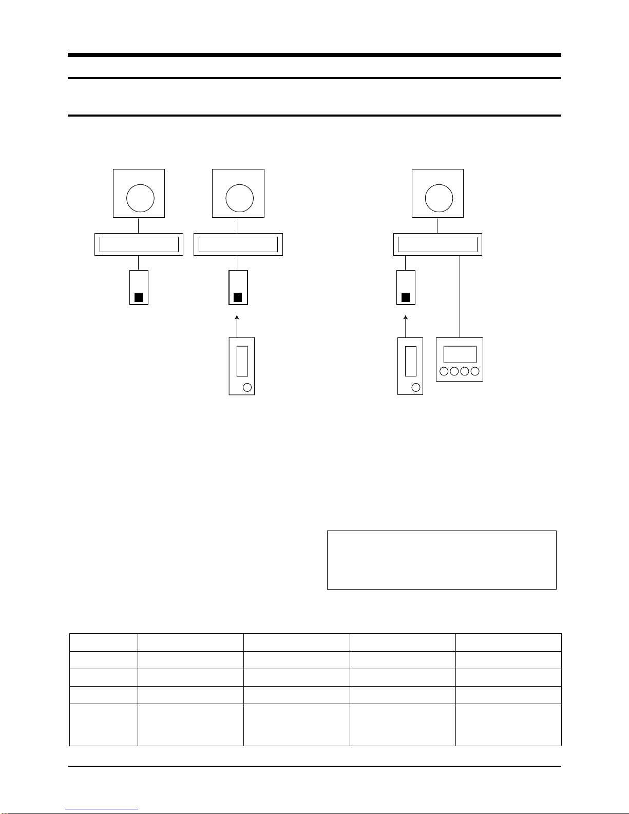
3-1 Example of Single unit Operation
1 chamber wired, wireless remote controller single operation and 1 chamber wireless remote controller +
wired remote controller combination control
Example of 1 chamber single operation
(wired or wireless remote controller)
* In case of 1 chamber single operation (wireless remote controller+wired remote controller), both setting of wired remote controller
to MASTER/SLAVE is available.
Example of 1 chamber single operation
(wireless + wired remote controller)
<To use wired & wireless remote controller simultaneously >
1. Put off the power.
4. Put on the power.
2. For the combined use of wireless remote
controller and wireless remote controller, put on
the option switch 4 of wired remote controller.
3. Putting off the option switch 4 of wired remote
controller disables the control by wireless remote
controller.
Wired Remote Controller Option Switch
DIP SWITCH NO
1
2
3
OPTION ITEM
Type of unit
Indoor unit control
Basic specification
SW ON
Cooling only
Group control
-
Caution :
• After resetting the option in the wired remote controller, be
sure to put the power on again so that the set option can
be applied.
SW OFF
Heat pump
Indoor unit 1 chamber control
-
Fixed to OFF
DEFAULT
OFF
OFF
4
wireless remote
controller
Samsung Electronics
Combined use of
Able to operate of wired
remote controller
(SLAVE MODE)
Disable to operate the
wireless remote controller
(MASTER MODE)
OFF
3-1
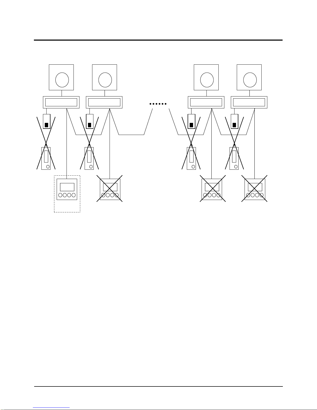
3-2 Exampe of Group Control Operation
Indoor unit
"A" chamber
Receiver
& Display
unit
Wireless
remote
controller
Outdoor unit
Receiver
& Display
unit
Receiver
& Display
unit
Receiver
& Display
unit
Wired remote
controller
Indoor unit
"B" chamber
"C" ~"N" chamber
Wireless
remote
controller
Outdoor unit
Wired remote
controller
"O" chamber
Wireless
remote
controller
Wired remote
controller
"P" chamber
Wireless
remote
controller
Wired remote
controller
3-2-1
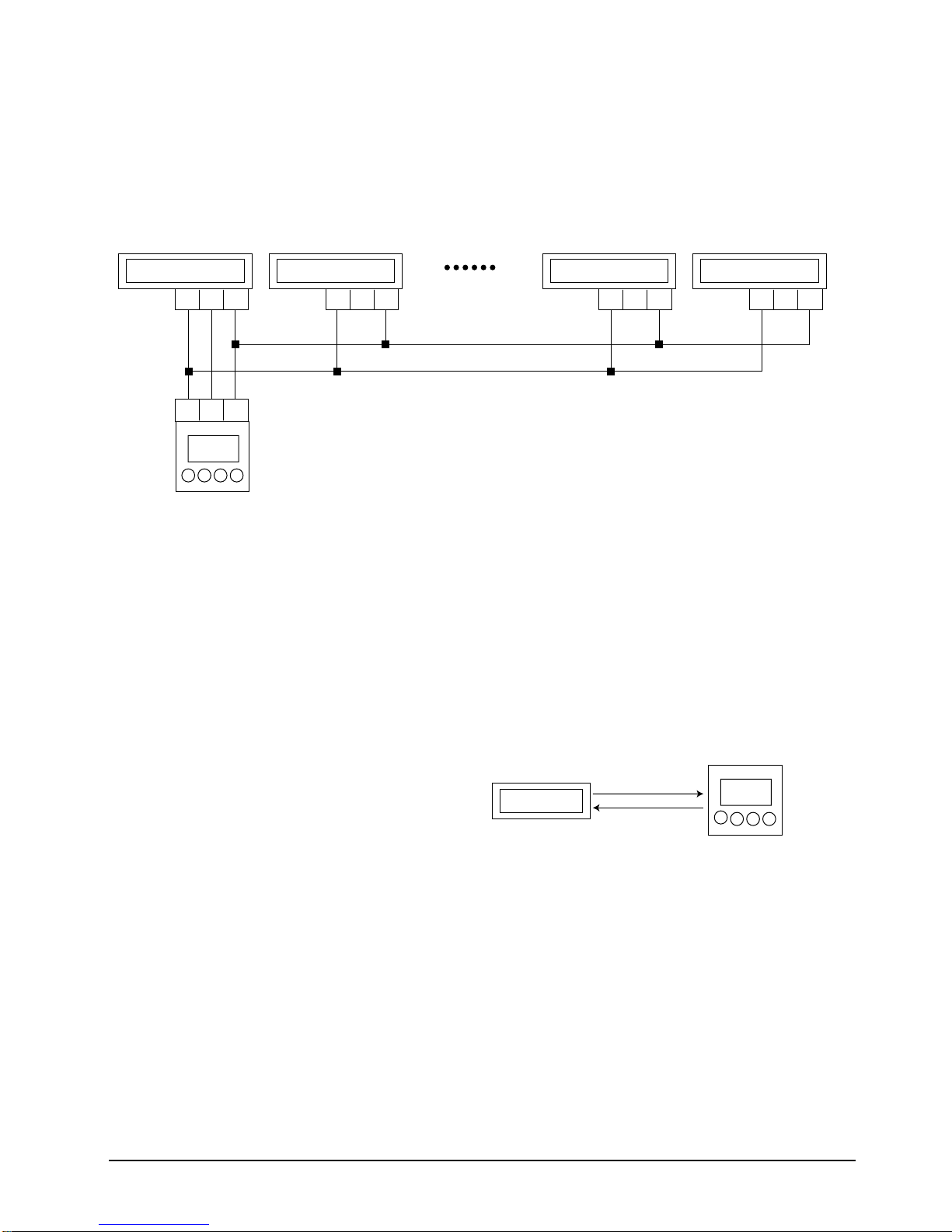
Group Control with wired remote controller
Figure. 16 Chamber Group Control (Wireless remote controller + wired remote controller) System
• The 16 chamber remote controller operation by wired remote controller can be simultaneously performed
all for 16 chambers through setting the 16 chambers to one group through one wired remote controller.
• While operated in Group, the control by wireless remote controller installed in all chambers (“A” ~ “P”)
is disabled except the wired remote controller installed in the “A” chamber and the simultaneous use
with the option item, the centralized controller is also disabled.
3-2-2
The group operation method by wired remote controller
1. Setting of indoor unit Main PCB
• Put off all of set power installed in each room.
• Remove the centralized controller if any is used
already.
• Connect the communicating line from “A”
• Connect the “R1”, “R2” and “R3” of indoor
chamber to “P” chamber.(R1<->R1, R3<->R3)
terminal board installed to the “R1”,”R2”,”R3”
1. Setting of indoor unit Main PCB
• Remove CN20 connector from main PCB of
Indoor unit except the one installed in “A” with
reference of the figure.
• Adjust the address of rotary switch of indoor unit
PCB in “B” chamber to “1”. In such a way, adjust
the address of digital switch up to chamber “P”.
• Put on the set power installed in each chamber.
of wired remote controller, respectively.
• Adjust the address of rotary switch of indoor
unit PCB in “A” chamber to “0”.
3-2
Samsung Electronics
Caution :
• During the connection, connect the “R1” of indoor unit terminal board installed in each chamber with “R1”.
• During the connection, connect the “R3” of indoor unit terminal board installed in each chamber with “R3”.
• Do not connect the terminal R2 of indoor unit terminal board from “B” to “F” chamber except “A” chamber.
• The option item, centralized controller shall be removed since the simultaneous use with wired remote controller is disable
during the group control.
• Adjust the address of indoor unit rotary switch installed in each chamber so that it might not be duplicated.
2. Setting of wired remote controller
• Put off the set power where the wired remote controller is installed.
• Put on the option switch SW 2 of wired remote controller.
• Put on the set power where the wired remote controller is installed.
Installation
Caution :
• The option can be applied when the power is put again after resetting the option of wired remote controller. Be sure to keep the
set power on/off after option setting.
Samsung Electronics
3-3
Installation
R1 R2 R3
R1 R2 R3
Indoor unit
"A" chamber
R1 R2 R3
Indoor unit
"B" chamber "C" ~ "N" chamber
R1 R2 R3
Indoor unit
"O" chamber
R1 R2 R3
Indoor unit
"P" chamber
Wired remote
controller
Indoor unit
RECEIVE MODE
SEND MODE
Wired remote
controller
3-2-3 Group Operation method of wired remote controller
Figure. 16 Chamber Group Control(wired remote controller) Connection Diagram
• Press the ON/OFF button of wired remote controller to be on.
At the time, the set installed from Achamber to P chamber is getting on in order with the interval of 2
seconds.
• Select the operation of auto/cooling/dehumidi-fying/blowing/heating by pressing MODE BUTTON.
• Select breeze/mild/strong wind by pressing the wind volume button.
• Adjust the temperature set button to set the desired temperature.
✽ For reference
• The communication between wired remote
controller and indoor unit is made through the
synchronization with the output signal of zero
cross detect circuit, and when 50Hz power is
used, it has the 50bps transmission speed and
when it has 60Hz power it has 60bps transmission
speed. The transmission data between the wired
remote controller and indoor unit is shown as in
the figure.
Since the communication data between wired remote
controller and indoor unit is consisting of total
10Byte, 2 seconds are required when using 50Hz
power.
• For the communicating time with 16 chambers
during the normal operation, 32 seconds are
required and for the time with 16 chamber during
the reservation operation, 64 seconds are required
due to the increase of communicating data.
3-4
Samsung Electronics
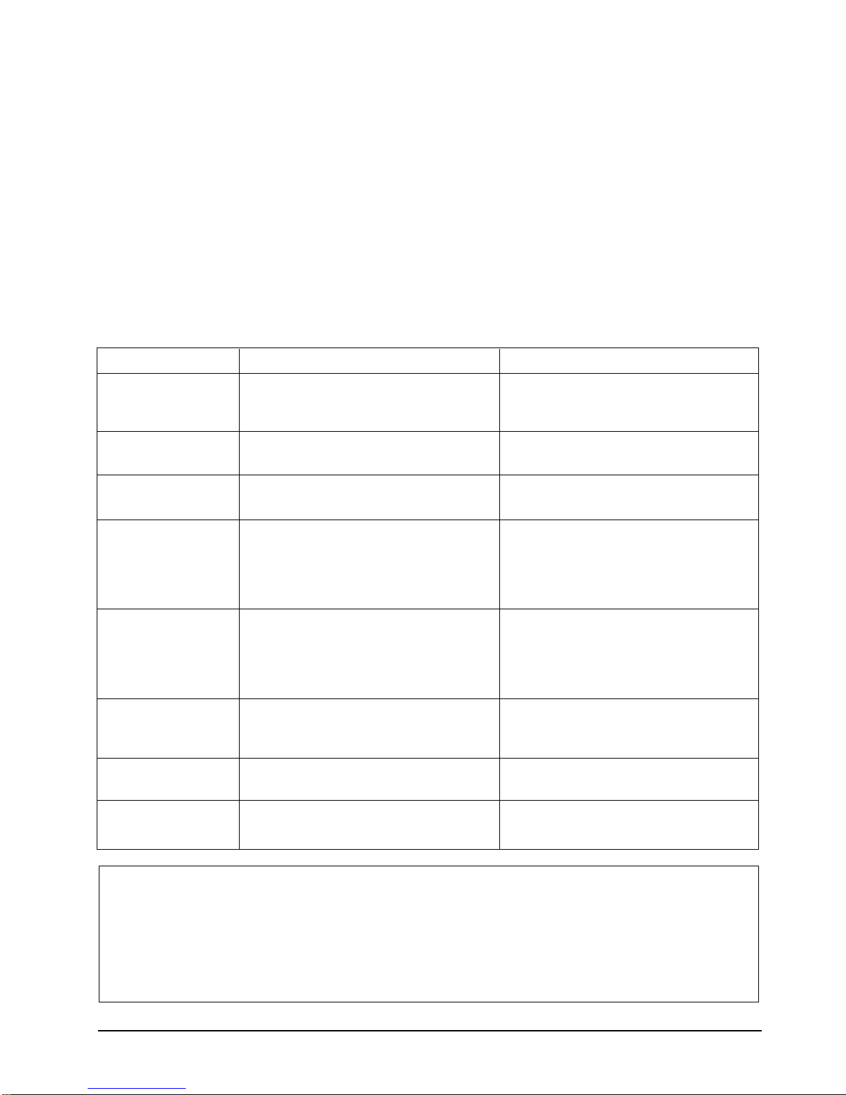
3-2-4 Startup method by wired remote controller
Installation
Start up of single operation
• Put on the set power.
• Adjust the address of digital switch of indoor
unit PCB to “0”.
• Put OFF the option switch 2 of wired remote
controller PCB.
• Put on the set power.
• Press the test button of wired remote controller
for more than 3 seconds.
Error Code
01
05
06
09
Indoor unit room thermistor error
Indoor unit pipe thermistor error
Outdoor unit thermistor error
Float switch open error
Meaning
• The set is operated for 3 minute by the forced
cooling operation and the set is off after 3
minute.
• The error occurring during the test operation is
displayed on the wired remote controller
windows and it shall be referred to the
following table.
Checking Area
• Indoor unit thermistor available or not and
disconnected
• Indoor unit PCB
• Indoor unit pipe thermistor
• Indoor unit PCB
• Outdoor unit thermistor
• Outdoor unit PCB
• Drain pump, float switch
• Drain system
• Dip SW2 of indoor unit main PCB
(If the drain pump is not installed, SW2 and
SW3 shall be at the Off position.)
0A
0C
0D
0L
Indoor unit
Wired remote controller ↔ indoor unit
communication error
Outdoor unit pipe thermistor error
Three phase power incorrect connecting error
↔ outdoor unit communicating error
• Indoor unit ↔ outdoor unit communicating
error
• Indoor unit ↔ outdoor unit communicating
cable
• Indoor unit PCB, Outdoor unit PCB
• Wired remote controller ↔ indoor unit
communication cable
• Indoor unit main PCB
• Outdoor unit pipe thermistor
• Outdoor unit PCB
• Three phase power connecting
• Outdoor unit PCB
Caution :
• Unless the address of digital switch of indoor unit PCB is set to “0” in case of “A” chamber single operation, the control by the wired
remote controller is disabled.
• The power of SET shall be put on again after the resetting of wired remote controller option so that the the set option can be applied.
Be sure to keep the power on/off of SET before and after the setting.
• The first digit of error code displayed during the single operation and group operation may be different. The first digit(MSB) stands for
the address of the set where the error occurs. Since it is the single operation, the address of SET is “0”.
Samsung Electronics
3-5
Installation
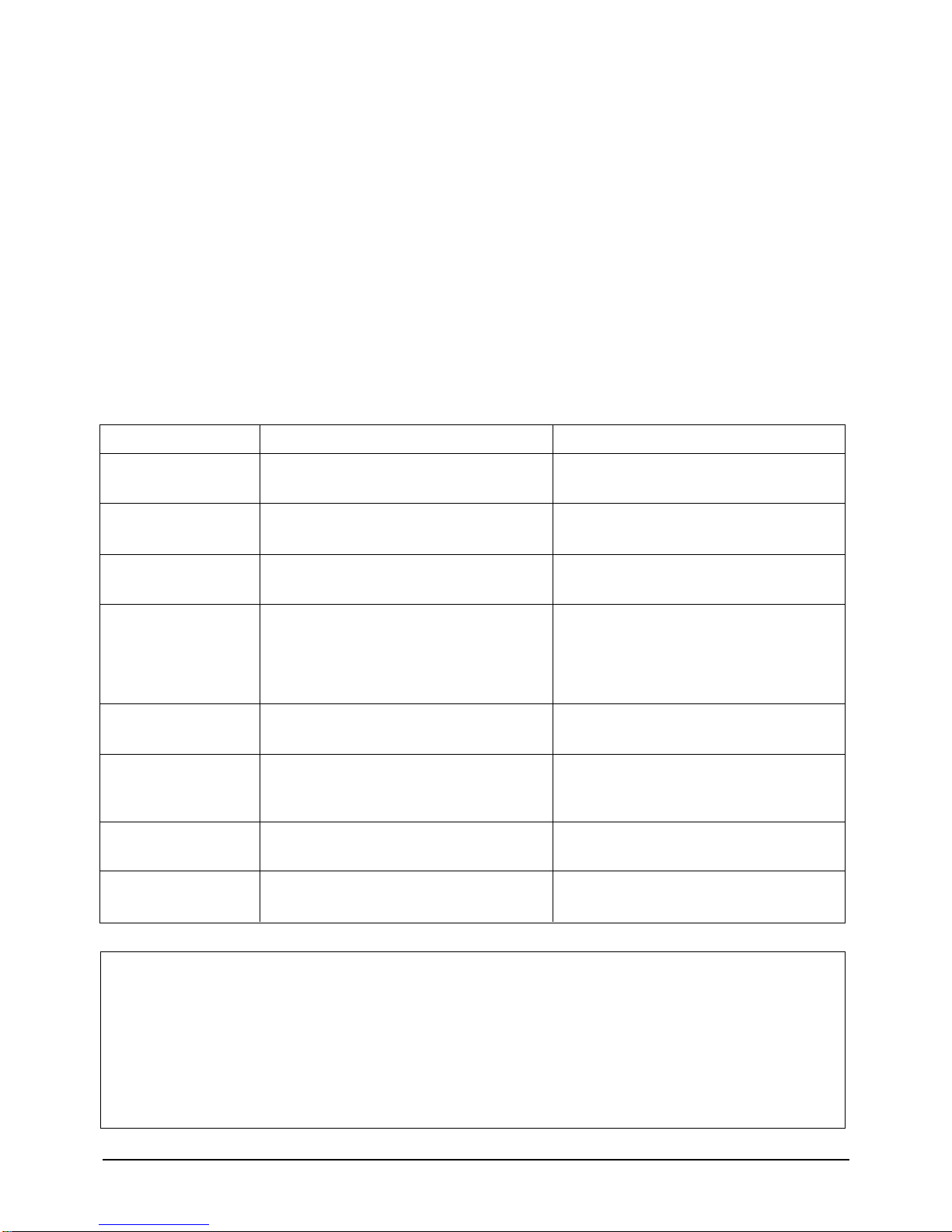
Startup of group operation
• Put off the power of SET.
• Adjust the addresses of digital switch of indoor
unit PCB to “0”~”15”, respectively.
• Put ON the option switch SW2 of wired remote
controller PCB.
• Put on the power of SET.
• On the wired remote controller display, the digits
“00” → “11” → “22” → are displayed up to “FF”.
After “FF” display, the wired remote controller is
automatically set to the preserved operation
status of indoor unit of chamber “A”.
Error Code
*1
*5
*6
Indoor unit room thermistor error
Indoor pipe thermistor error
Outdoor unit thermistor error
Meaning
• If the current SET of chamber “A” is ON, put the
set off by pressing the ON/OFF button.
Only at the SET off of chamber “A”, the TEST mode
is enabled.
• Press the TEST BUTTON of wired remote
controller for more than 3 seconds.
• If the SET is operating for 3 minutes through
forced cooling operation, the SET is off after 2
minutes.
• The Error occurring in the TEST operation
displays in the wired remote controller display
window and is referred to the following table.
Checking Area
• Indoor unit thermistor exist or not disconnected
• Indoor unit PCB
• Indoor unit pipe thermistor
• Indoor unit PCB
• Outdoor unit thermistor
• Outdoor unit PCB
• Drain pump, float switch
• Drain system
• Dip SW2 of indoor unit main PCB
(If drain pump is not installed, SW2 and SW3
shall be at OFF position.)
• Indoor unit ↔ Outdoor unit communication cable
• Indoor unit PCB, outdoor unit PCB
• Wired remote controller ↔ indoor unit
communication cable
• Indoor unit main PCB
• Outdoor unit pipe thermistor
• Outdoor unit PCB
• Threem phase power connecting
• Outdoor unit PCB
*A
*C
*D
*9
*L
Float switch open error
Indoor unit ↔ outdoor unit communication error
Wired remote controller ↔ indoor unit
communication error
Outdoor unit pipe thermistor error
Three phase power incorrect connecting error
Caution :
• Test operation is disabled when the chamber “A” is on after initialization of wired remote controller.
• The communication time between wired remote controller and indoor unit is required for 2 seconds. If any one of set is ON, be sure to
put it off by pressing the ON/OFF button and start the TEST operation after 35 seconds at minimum.(The communication time with all
chambers : 16 x 2 seconds = 32seconds)
• For the reservation operation, the communication time between all 16 chambers is required for 64 seconds due to the increase of
communication data.
• The first digit (MSB) of error code displayed during the group operation stands for the address of SET where the error occurs.
3-6
Samsung Electronics
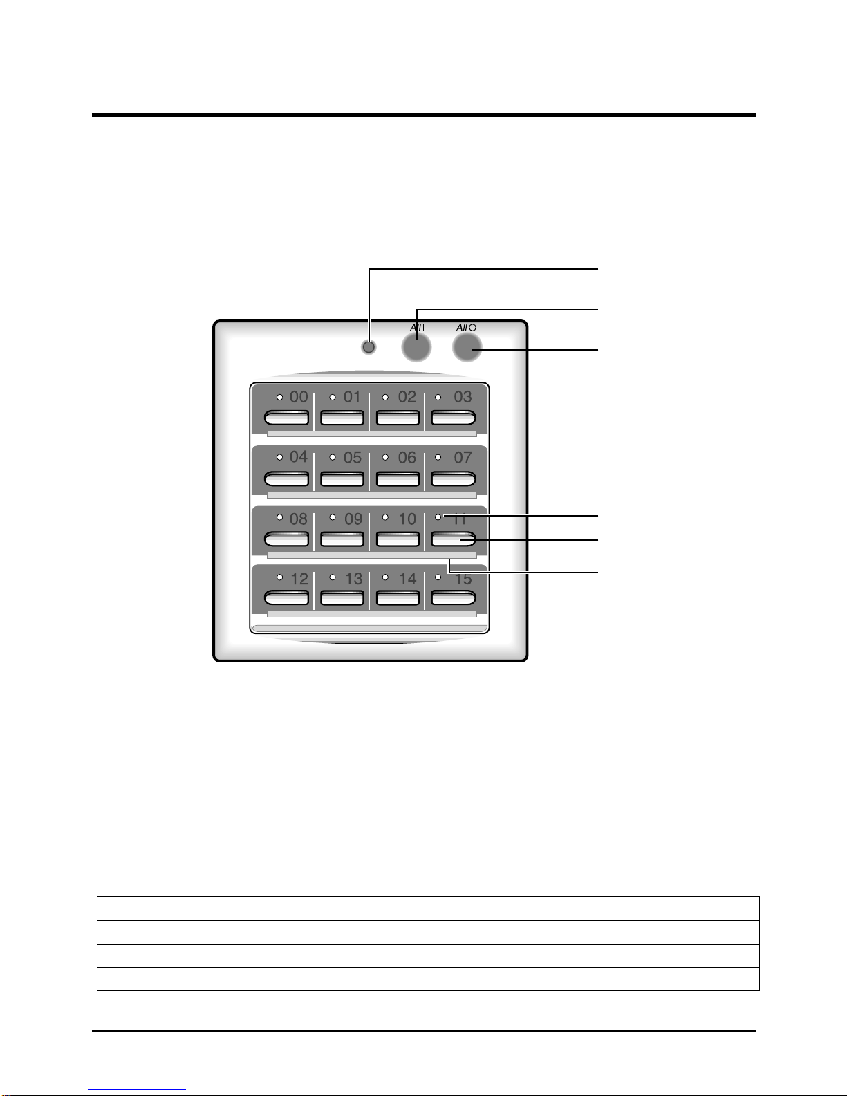
3-3 Centralized Controller Operation
3-3-1 Appearance and characteristics of Centralized Controller
The centralized controller is installed on the wall.
The centralized controller is an optional accessory.
Operating lamp
All On button
All Off button
NOTE : Operating lamp comes on when at least one air conditioner
connected to the centralized controller is operating.
• Since the centralized controller has the relay
equipment, the option mounted on the indoor
unit, the On/Off can be set for 16 chambers
through the modem communication.
• Linkage of wired remote controller to wired
remote controller is available by 3 kinds of level.
BUTTON NAME
ALL1
ALL0
"01" ~ "16"
• To put on all 16 chambers' set.
• To put off all 16 chambers' set.
• To put on/off set assigned with the number.
On/Off indicators
On/Off buttons
Index
• The maximum extended distance of 1 Km is
possible through modem communication. (the
relay equipment is installed at the option item,
indoor unit)
• The connection by non-polarity method is easy.
FUNCTION
Samsung Electronics
3-7
 Loading...