

Samsung DH140CAV, DH105CAV, UH105CAV, UH140CAV Installation Manual
ENGLISH
System Air Conditioner
(Cooling and Heating)
INSTALLATION
MANUAL
Indoor Unit Outdoor Unit
DH140CAV UH140CAV
DH105CAV UH105CAV
ESPAÑOLFRANÇAIS
DB98-29515A(1)SE F
Air Marketing Group LLC
141 Kinderkamack Rd, Park Ridge, NJ 07656 Tel: 201-782-1782 Fax: 201-782-1783 Web: www.amgair.com Email: info@amgair.com
E-2
Safety Precautions
(Carefully follow the precautions listed below because they are essential to guarantee the safety of the equipment.)
WARNING
• Always disconnect the air conditioner from the power supply before servicing it or
accessing its internal components.
•
Verify that installation and testing operations are performed by qualified personnel.
• Verify that the air conditioner is not installed in an easily accessible area.
GENERAL INFORMATION
Carefully read the content of this manual before installing the air conditioner and store the manual in a safe place in order to be
able to use it as reference after installation.
For maximum safety, installers should always carefully read the following warnings.
Store the operation and installation manual in a safe location and remember to hand it over to the new owner if the
air conditioner is sold or transferred.
This manual explains how to install an indoor unit with a split system with two SAMSUNG units. The use of other types of units
with different control systems may damage the units and invalidate the warranty. The manufacturer shall not be responsible for
damages arising from the use of non compliant units.
The manufacturer shall not be responsible for damage originating from unauthorized changes or the improper connection of
electric and requirements set forth in the “Operating limits” table, included in the manual, shall immediately invalidate the warranty.
The air conditioner should be used only for the applications for which it has been designed: the indoor unit is not suitable to be
installed in areas used for laundry.
Do not use the units if damaged. If problems occur, switch the unit off and disconnect it from the power supply.
In order to prevent electric shocks, fires or injuries, always stop the unit, disable the protection switch and contact SAMSUNG’s
technical support if the unit produces smoke, if the power cable is hot or damaged or if the unit is very noisy.
Always remember to inspect the unit, electric connections, refrigerant tubes and protections regularly. These operations should be
performed by qualified personnel only.
The unit contains moving parts, which should always be kept out of the reach of children.
Do not attempt to repair, move, alter or reinstall the unit. If performed by unauthorized personnel, these operations may cause
electric shocks or fires.
Do not place containers with liquids or other objects on the unit.
All the materials used for the manufacture and packaging of the air conditioner are recyclable.
The packing material and exhaust batteries of the remote control(optional) must be disposed of in accordance with current laws.
The air conditioner contains a refrigerant that has to be disposed of as special waste. At the end of its life cycle, the air conditioner
must be disposed of in authorized centers or returned to the retailer so that it can be disposed of correctly and safely.
INSTALLING THE UNIT
IMPORTANT: When installing the unit, always remember to connect first the refrigerant tubes, then the electrical lines.
Always disassemble the electric lines before the refrigerant tubes.
Upon receipt, inspect the product to verify that it has not been damaged during transport. If the product appears damaged,
DO NOT INSTALL it and immediately report the damage to the carrier or retailer (if the installer or the authorized technician has
collected the material from the retailer.)
After completing the installation, always carry out a functional test and provide the instructions on how to operate
the air conditioner to the user.
Do not use the air conditioner in environments with hazardous substances or close to equipment that release free flames to avoid
the occurrence of fires, explosions or injuries.
POWER SUPPLY LINE, FUSE OR CIRCUIT BREAKER
Always make sure that the power supply is compliant with current safety standards. Always install the air conditioner in compliance
with current local safety standards.
Always verify that a suitable grounding connection is available.
Verify that the voltage and frequency of the power supply comply with the specifications and that the installed power is sufficient
to ensure the operation of any other domestic appliance connected to the same electric lines.
Always verify that the cut-off and protection switches are suitably dimensioned.
Verify that the air conditioner is connected to the power supply in accordance with the instructions provided in the wiring
diagram included in the manual.
Always verify that electric connections (cable entry, section of leads, protections…) are compliant with the electric specifications
and with the instructions provided in the wiring scheme. Always verify that all connections comply with the standards applicable
to the installation of air conditioners.
Air Marketing Group LLC
141 Kinderkamack Rd, Park Ridge, NJ 07656 Tel: 201-782-1782 Fax: 201-782-1783 Web: www.amgair.com Email: info@amgair.com

E-3
ENGLISH
Contents
Preparation for installation . . . . . . . . . . . . . . . . . . . . . . . . . . . . . . . . . . . . . . . . . . . . . . . . . . . . . . . . . . . . 4
Deciding on where to install the indoor unit . . . . . . . . . . . . . . . . . . . . . . . . . . . . . . . . . . . . . . . . . . 5
Indoor unit installation . . . . . . . . . . . . . . . . . . . . . . . . . . . . . . . . . . . . . . . . . . . . . . . . . . . . . . . . . . . . . . . . 8
Purging the unit . . . . . . . . . . . . . . . . . . . . . . . . . . . . . . . . . . . . . . . . . . . . . . . . . . . . . . . . . . . . . . . . . . . . . . 9
Connecting the refrigerant pipe . . . . . . . . . . . . . . . . . . . . . . . . . . . . . . . . . . . . . . . . . . . . . . . . . . . . . . 10
Cutting/Flaring the pipes . . . . . . . . . . . . . . . . . . . . . . . . . . . . . . . . . . . . . . . . . . . . . . . . . . . . . . . . . . . . . 11
Performing leak test & insulation . . . . . . . . . . . . . . . . . . . . . . . . . . . . . . . . . . . . . . . . . . . . . . . . . . . . . 12
Drain hose installation . . . . . . . . . . . . . . . . . . . . . . . . . . . . . . . . . . . . . . . . . . . . . . . . . . . . . . . . . . . . . . . . 13
Connecting the connection cord . . . . . . . . . . . . . . . . . . . . . . . . . . . . . . . . . . . . . . . . . . . . . . . . . . . . . 15
Adjusting air flow . . . . . . . . . . . . . . . . . . . . . . . . . . . . . . . . . . . . . . . . . . . . . . . . . . . . . . . . . . . . . . . . . . . . . 17
Setting up the mode option . . . . . . . . . . . . . . . . . . . . . . . . . . . . . . . . . . . . . . . . . . . . . . . . . . . . . . . . . . 18
Assigning address to indoor unit . . . . . . . . . . . . . . . . . . . . . . . . . . . . . . . . . . . . . . . . . . . . . . . . . . . . . 28
Additional functions . . . . . . . . . . . . . . . . . . . . . . . . . . . . . . . . . . . . . . . . . . . . . . . . . . . . . . . . . . . . . . . . . . 29
Filter Replacement(Optional) . . . . . . . . . . . . . . . . . . . . . . . . . . . . . . . . . . . . . . . . . . . . . . . . . . . . . . . . . 31
Drain pump installation(Optional) . . . . . . . . . . . . . . . . . . . . . . . . . . . . . . . . . . . . . . . . . . . . . . . . . . . . 32
Technical Specification & Product feature . . . . . . . . . . . . . . . . . . . . . . . . . . . . . . . . . . . . . . . . . . . . . 34
Troubleshooting . . . . . . . . . . . . . . . . . . . . . . . . . . . . . . . . . . . . . . . . . . . . . . . . . . . . . . . . . . . . . . . . . . . . . . 35
Additional accessories . . . . . . . . . . . . . . . . . . . . . . . . . . . . . . . . . . . . . . . . . . . . . . . . . . . . . . . . . . . . . . . . 38
Air Marketing Group LLC
141 Kinderkamack Rd, Park Ridge, NJ 07656 Tel: 201-782-1782 Fax: 201-782-1783 Web: www.amgair.com Email: info@amgair.com
E-4
Preparation for installation
When deciding on the location of the air conditioner with the owner,
the following restrictions must be taken into account.
Do NOT install the air conditioner in a location where it will come into
contact with the following elements:
Combustible gases
Saline air
Machine oil
Sulphide gas
Special environmental conditions
If you must install the unit in such conditions, first consult your dealer.
General
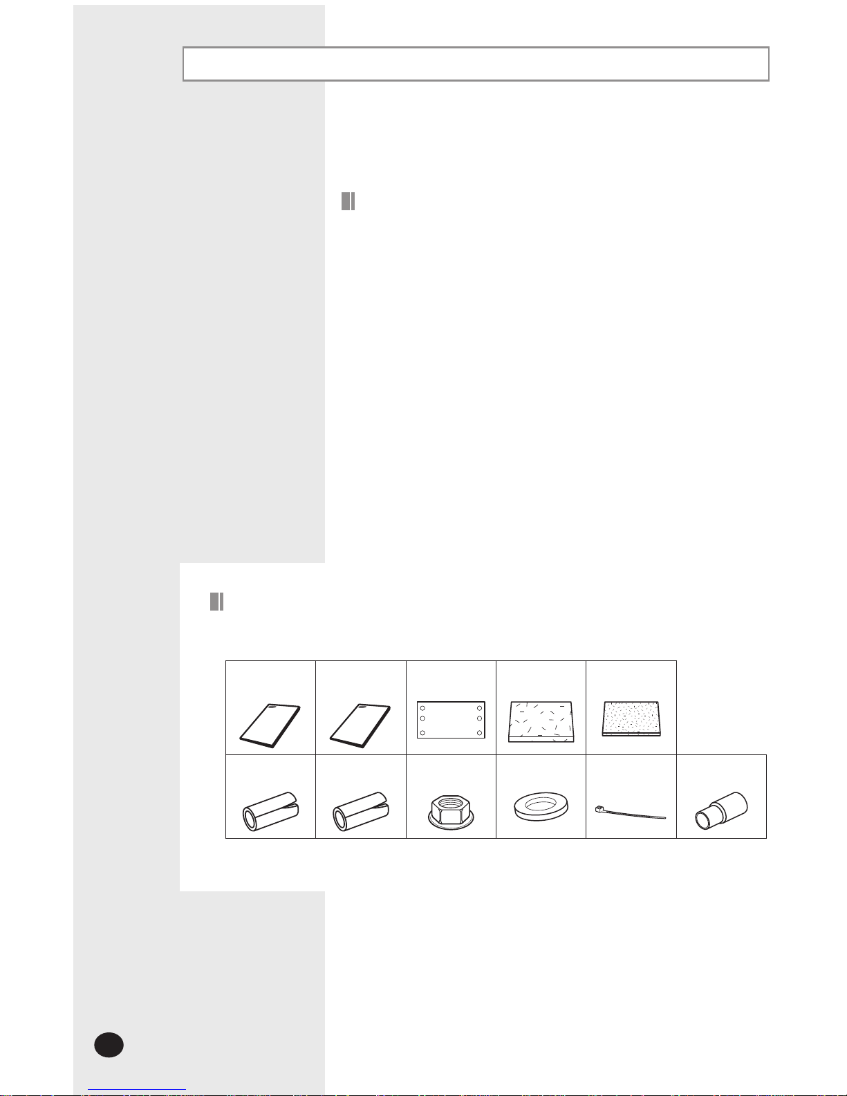
Accessories
The following accessories are supplied with the indoor unit.
The type and quantity may differ depending on the specifications.
User’s
manual
Installation
manual
Pattern sheet Insulation drain Insulation
cover pipe
Insulation pipe Insulation
drain pipe
Nut Rubber Cable-tie Drain socket
Avoid installing the air conditioner:
In areas where it is exposed to direct sunlight. Close to heat sources.
In damp areas or locations where it could come into contact with water
(for example rooms used for laundry)
In areas where curtains and furniture could affect the supply and discharge of air.
Without leaving the required minimum space around the unit (as shown in the
drawing).
In scarcely ventilated areas.
On surfaces that are unable to support the weight of the unit without deforming,
breaking or causing vibrations during the use of the air conditioner.
In a position that does not enable the condensate drainage pipe to be correctly
installed (at the end of the installation. It is always essential to check the efficiency
of the drainage system.)
Air Marketing Group LLC
141 Kinderkamack Rd, Park Ridge, NJ 07656 Tel: 201-782-1782 Fax: 201-782-1783 Web: www.amgair.com Email: info@amgair.com
E-5
ENGLISH
Deciding on where to install the indoor unit
Indoor unit
There must be no obstacles near the air inlet and outlet.
Install the indoor unit on a ceiling that can support its weight.
Maintain sufficient clearance around the indoor unit.
Make sure that the water dripping from the drain hose runs away correctly and safely.
The indoor unit must be installed in this way, that they are out of public access. (Not touchable by the users)
After connecting a chamber, insulate the connection part between the indoor unit and the chamber with t10 or
thicker insulation. Otherwise, there can be air leak or dew from the connection part.
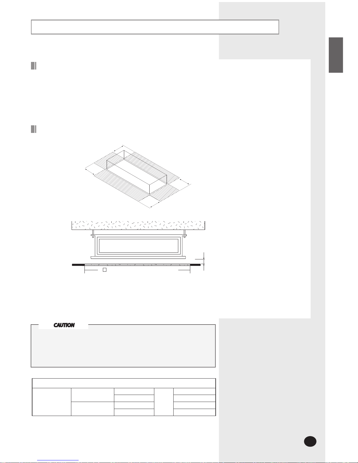
Space requirements for indoor unit
0.196inch(5mm)
You must have 1.969inch(5mm) or more space between the ceiling and the bottom of indoor unit. Otherwise, the noise from the
vibration of indoor unit may bother the user.When the ceiling is under construction, the hole for check-up must be made to take
service, clean and repair the unit.
It is possible to install the unit at an height of between 7.2ft(2.2m) ~ 8.2ft(2.5m)from the ground, if the unit has a duct with a well
defined lenght (1ft(304.8mm) or more), to avoid fan motor blower contact.
4.58ft(1398mm) X 1.3ft(400mm) or more
(A space for repair and service)
The units must be installed according to distances declared, in order to
permit accessibility from each side, either to guarantee correct operation
of maintenance or repairing products.
The unit’s parts must be reachable and removable completely under
safety condition (for people or things).
CAUTION
Weight
Net weight
Indoor Unit
DH105CAV
kg(Ib)
39(86)
DH140CAV 55(121.1)
Outdoor Unit
UH105CAV 90(198.4)
UH140CAV 94(207.2)
4.9ft or more
4.9ft or more
4.9ft or more
4.9ft or more
Air Marketing Group LLC
141 Kinderkamack Rd, Park Ridge, NJ 07656 Tel: 201-782-1782 Fax: 201-782-1783 Web: www.amgair.com Email: info@amgair.com

E-6
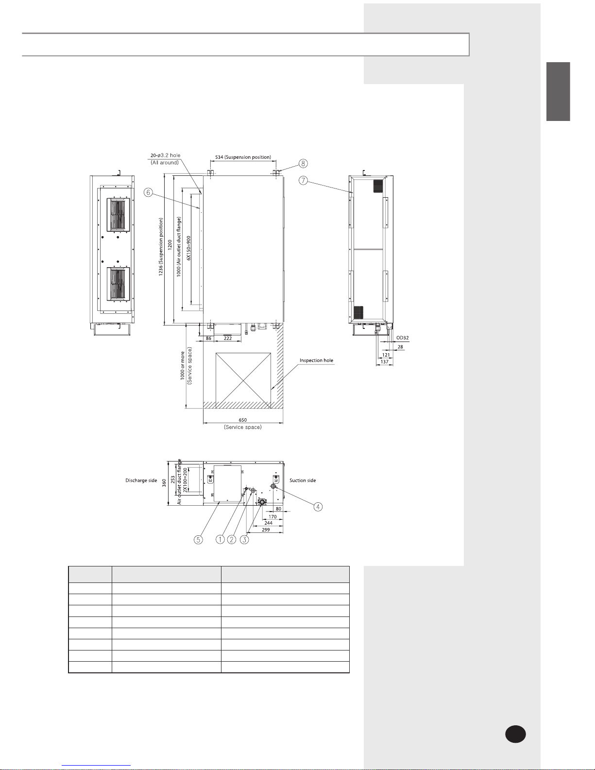
Drawing of the indoor unit
Unit : mm
No. Name Description
1 Liquid pipe connection ø9.52
2 Gas pipe connection ø15.88
3 Drain pipe connection OD32 ID26(without drain pump)
4 Drain pipe connection Using drain pump (Optional)
5 Power supply connection
6 Air discharge flange
7 Air filter
8 Hook M8~M10
102
Deciding on where to install the indoor unit (Continued)
DH105CAV
Air Marketing Group LLC
141 Kinderkamack Rd, Park Ridge, NJ 07656 Tel: 201-782-1782 Fax: 201-782-1783 Web: www.amgair.com Email: info@amgair.com
E-7
ENGLISH
102
No. Name Description
1 Liquid pipe connection ø9.52
2 Gas pipe connection ø19.05
3 Drain pipe connection OD32 ID26(without drain pump)
4 Drain pipe connection Using drain pump (Optional)
5 Power supply connection
6 Air discharge flange
7 Air filter
8 Hook M8~M10
Unit : mm
DH140CAV
Air Marketing Group LLC
141 Kinderkamack Rd, Park Ridge, NJ 07656 Tel: 201-782-1782 Fax: 201-782-1783 Web: www.amgair.com Email: info@amgair.com
E-8
Indoor unit installation
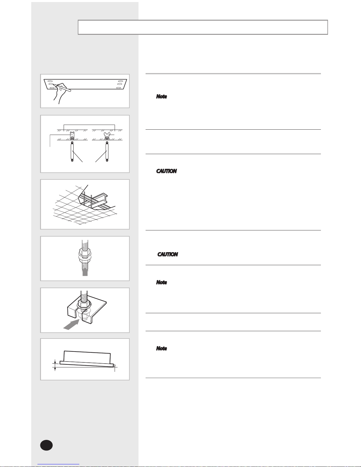
1
Place the pattern sheet on the ceiling at the spot where you want to install
the indoor unit.
Note Since the diagram is made of paper, it may shrink or stretch
slightly due to temperature or humidity. For this reason,
before drilling the holes maintain the correct dimensions
between the markings.
2
Insert bolt anchors. Use existing ceiling supports or construct a suitable
support as shown in figure.
3
Install the suspension bolts depending on the ceiling type.
CAUTION Ensure that the ceiling is strong enough to support the
weight of the indoor unit. Before hanging the unit, test the
strength of each attached suspension bolt.
If the length of suspension bolt is more than 4.92ft(1.5m),
it is required to prevent vibration.
If this is not possible, create an opening on the false ceiling
in order to be able to use it to perform the required operations on the indoor unit.
4
Screw eight nuts to the suspension bolts making space for hanging the
indoor unit.
CAUTION You must install all the suspension rods.
5
Hang the indoor unit to the suspension bolts between two nuts.
Note Piping must be laid and connected inside the ceiling when
suspending the unit. If the ceiling is already constructed,
lay the piping into position for connection to the unit before
placing the unit inside the ceiling.
6
Screw the nuts to suspend the unit.
7
Adjust level of the unit by using measurement plate for all 4 sides.
Note For proper drainage of condensate, give a 0.118inch(3mm) slant
to the left or right side of the unit which will be connected with
the drain hose, as shown in the figure. Make a tilt when you wish
to install the drain pump, too.
It is recommended to install the refnet joint before installing the indoor unit.
Concrete
Suspension bolt(M8)-field supply
Hole in anchor
hole in plug
Ceiling support
When the drain hose is installed to the right.
Drain hose port
0.118inch(3mm)
Insert
Air Marketing Group LLC
141 Kinderkamack Rd, Park Ridge, NJ 07656 Tel: 201-782-1782 Fax: 201-782-1783 Web: www.amgair.com Email: info@amgair.com
E-9
ENGLISH
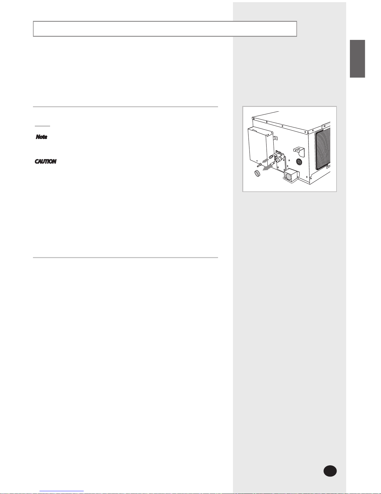
From factory the unit is supplied and set with a pre-charge of nitrogen gas
(insert gas). Therefore, all insert gas must be purged before connecting the
assembly piping.
Unscrew the pinch pipe at the end of each refrigerant pipe.
Result: All inert gas escapes from the indoor unit.
Note To prevent dirt or foreign objects from getting into the pipes
during installation, do NOT remove the pinch pipe completely until
you are ready to connect the piping.
CAUTION Connect the indoor and outdoor units using pipes with flared
connections(not supplied). For the lines, use insulated,
unwelded, degreased and deoxidized copper pipe,(Cu DHP
type to ISO 1337), suitable for operating pressures of at least
4200kPa and for a burst pressure of at least 20700kPa. Copper
pipe for hydro-sanitary applications is completely unsuitable.
For sizing and limits (height difference, line length, max. bends,
refrigerant charge, etc.) see the outdoor unit installation
manual.
All refrigerant connection must be accessible, in order to
permit either unit maintenance or removing it completely.
Purging the unit
The designs and shape are subject to
change according to the model.
Air Marketing Group LLC
141 Kinderkamack Rd, Park Ridge, NJ 07656 Tel: 201-782-1782 Fax: 201-782-1783 Web: www.amgair.com Email: info@amgair.com
E-10
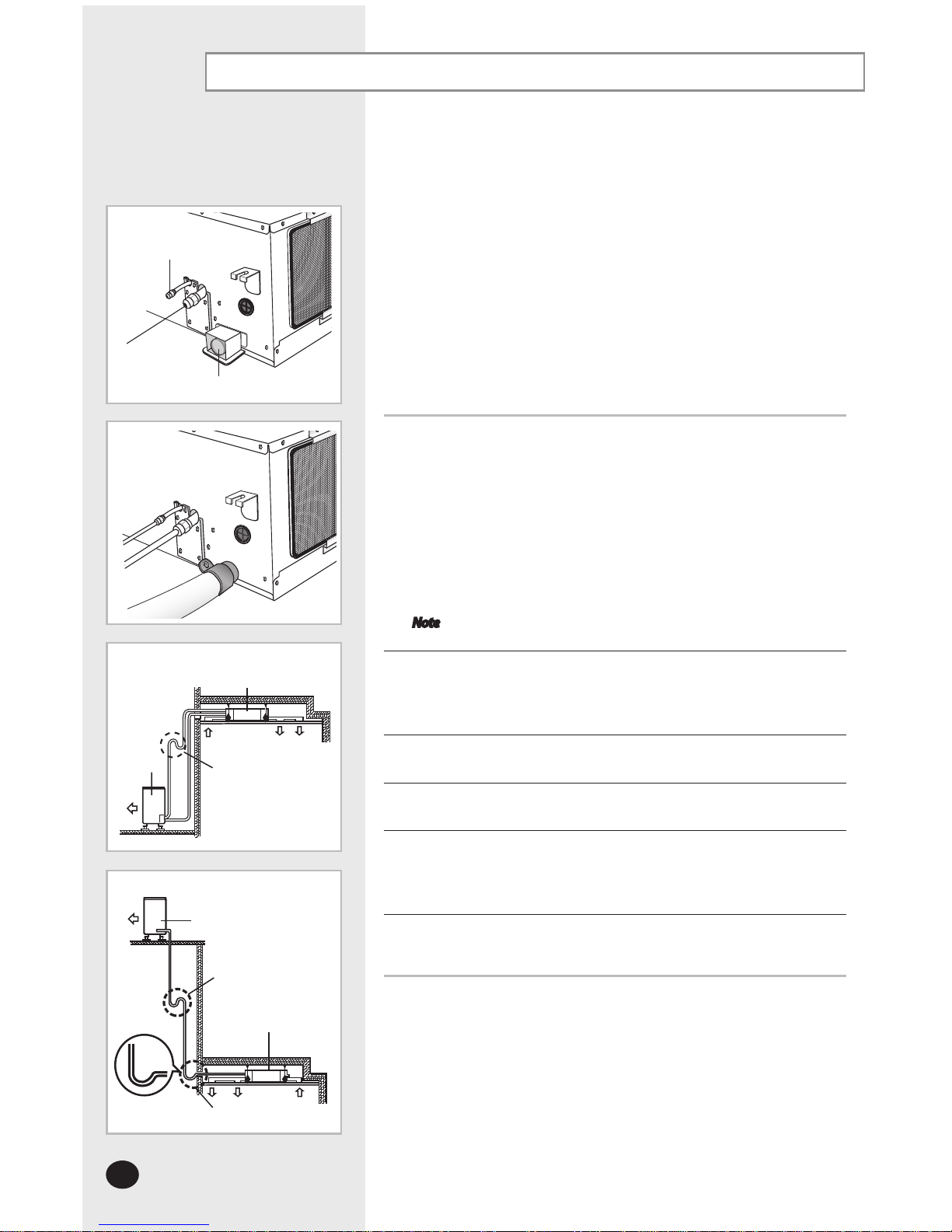
Connecting the refrigerant pipe
There are two refrigerant pipes of different diameters:
A smaller one for the liquid refrigerant
A larger one for the gas refrigerant
The thickness of tube should not be less than 0.039inch(1mm).
The inside of copper tube must be clean & has no dust.
The connection procedure for the refrigerant pipes varies according to the
exit position of the pipes from the indoor unit, as seen when facing the indoor
in the “A” side.
Liquid refrigerant port
Gas refrigerant port
Drain hose connection port
1
Remove the pinch pipe on the pipes and connect the assembly pipes
to each pipe, tightening the nuts, first manually and then with a torque
wrench, a spanner applying the following torque.
Outer Diameter Torque (ft.lb)
6.35 mm (1/4”)
9.52 mm (3/8”)
12.70 mm (1/2”)
15.88 mm (5/8”)
19.05 mm (3/4”)
13.2
31.0
40.6
48.0
73.6
Note If the pipes must be shortened refer to page 11.
2
Must use insulator which is thick enough to cover the refrigerant tube to
protect the condensate water on the outside of pipe falling onto the floor
and the efficiency of the unit will be better.
3
Cut off any excess foam insulation.
4
Be sure that there must be no crack or wave on the bended area.
5
It would be necessary to double the insulation thickness(0.393inch(10mm)or
more)to prevent condensation even on the insulator when if the installed area
is warm and humid.
6
Shape an oil trap as shown in figure the oil trap must be fomed every level
difference of 32.8ft(10m).
Drain hose connection port
Liquid refrigerant port
Gas refrigerant
port
A
a. When the indoor unit is above the outdoor unit
Indoor unit
Oil trap (Must be installed
every 32.8f
t(10m))
Outdoor unit
b. When the outdoor unit is above the indoor unit
Outdoor unit
Oil trap
(Must be installed
every 32.8f
t(10m))
Oil trap
(suction tube)
indoor unit
Radius
1.968inch
(50mm)
Air Marketing Group LLC
141 Kinderkamack Rd, Park Ridge, NJ 07656 Tel: 201-782-1782 Fax: 201-782-1783 Web: www.amgair.com Email: info@amgair.com
E-11
ENGLISH
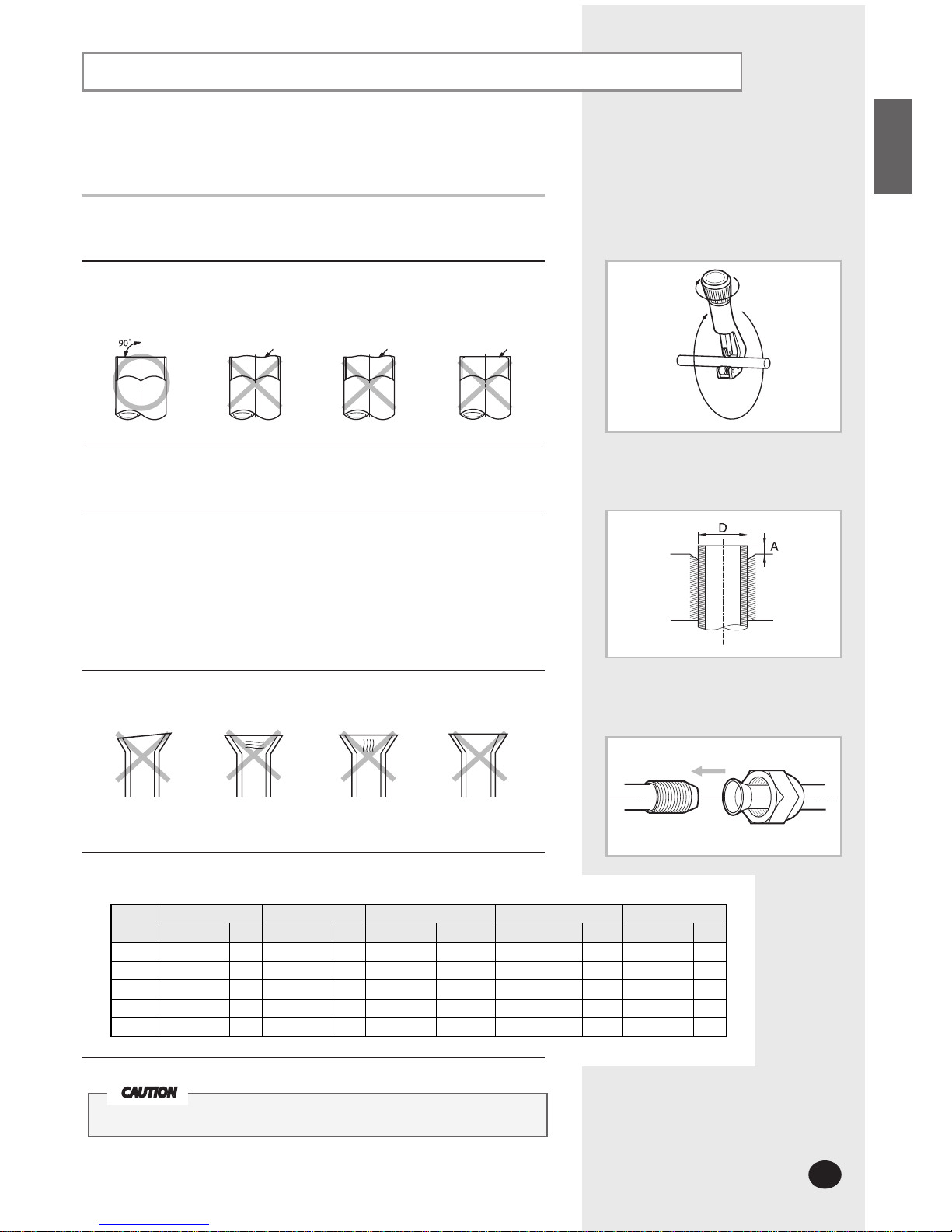
Cutting/Flaring the pipes
CAUTION
In case of welding the pipe, you must weld with nitrogen gas blowing.
Inclined Damaged Surface Cracked Uneven Thickness
Oblique Rough Burr
1
Make sure that you have the required tools available.
(pipe cutter, reamer, flaring tool and pipe holder).
2
If you wish to shorten the pipes, cut it with a pipe cutter, taking care to ensure
that the cut edge remains at a 90° angle with the side of the pipe. Refer to the
illustrations below for examples of edges cut correctly and incorrectly.
3
To prevent any gas from leaking out, remove all burrs at the cut edge of the
pipe, using a reamer.
4
Slide a flare nut on to the pipe and modify the flare.
Outer diameter (D) Depth (A)
6.35 mm (1/4”)
9.52 mm (3/8”)
12.70 mm (1/2”)
15.88 mm (5/8”)
19.05 mm (3/4”)
0.051 inch
0.070 inch
0.078 inch
0.086 inch
0.086 inch
5
Check that the flaring is correct, referring to the illustrations below for
examples of incorrect flaring.
6
Align the pipes and tighten the flare nuts first manually and then with
a torque wrench, applying the following torque.
Valve
Flare nut Valve cap Pressure port cap Valve needle Pressure port
Wrench(inch)
ft.lb
Wrench(inch)
ft.lb
Wrench(inch)
ft.lb
Wrench(inch)
ft.lb
Wrench(inch)
ft.lb
1/4" 0.67 13.2 0.91 14.8 0.7 11.8~13.3 Allen(hex.) 0.2 6.64 - 0.25
3/8" 0.87 31.0 0.91 14.8 0.7 11.8~13.3 Allen(hex.) 0.2 6.64 - 0.25
1/2" 1.02 40.6 1.14 29.5 0.7 11.8~13.3 Allen(hex.) 0.2 9.59 - 0.25
5/8" 1.14 48.0 1.14 29.5 0.7 11.8~13.3 Allen(hex.) 0.2 9.59 - 0.25
3/4" 1.42 73.6 1.5 29.5 0.7 11.8~13.3 Allen (hex.) 0.2 9.59 - 0.25
Air Marketing Group LLC
141 Kinderkamack Rd, Park Ridge, NJ 07656 Tel: 201-782-1782 Fax: 201-782-1783 Web: www.amgair.com Email: info@amgair.com
E-12
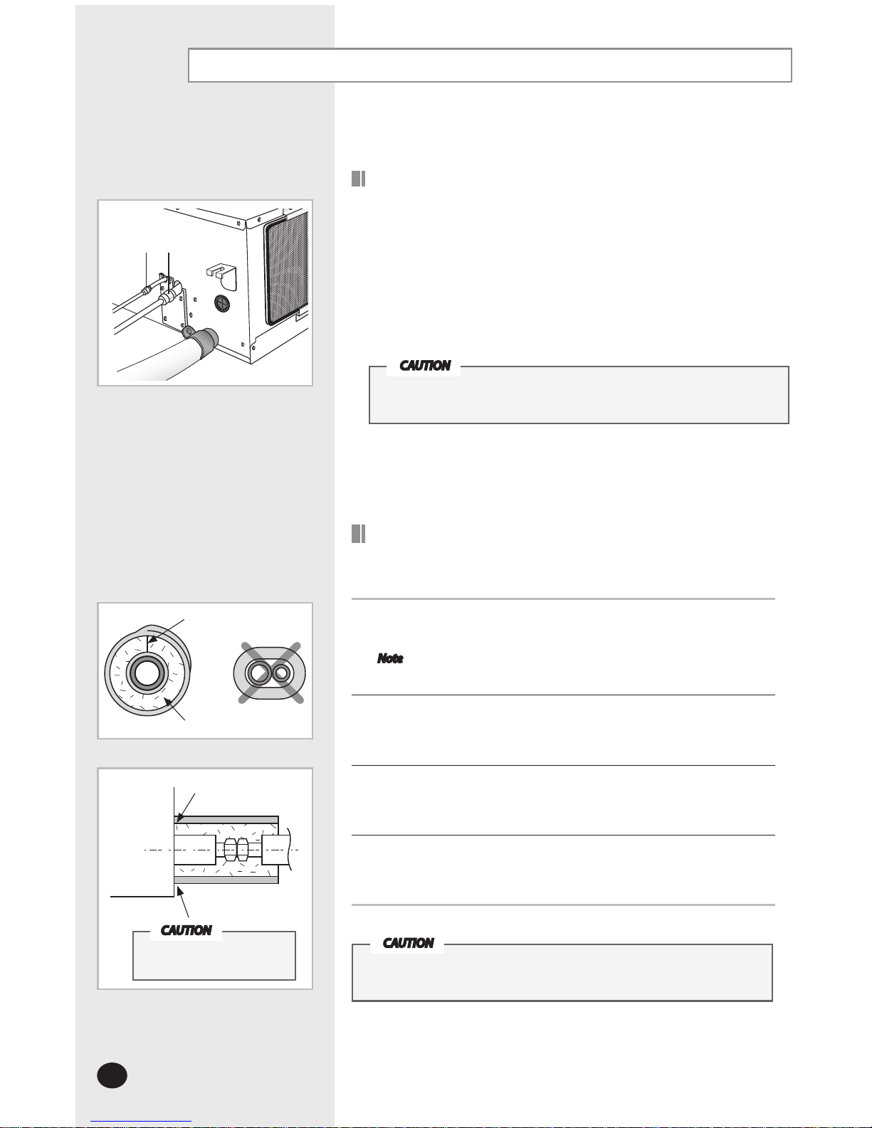
Performing leak test & insulation
A B
No gap
NBR(0.511inch(13mm)or
thicker)
Insulation cover pipe
Indoor unit
Be sure to overlap
the insulation
CAUTION
Must fit tightly against body
without any gap.
Insulation
Once you have checked that there are no leaks in the system,
you can insulate the piping and hose.
1
To avoid condensation problems, place T0.511inch(13mm) or thicker
Acrylonitrile Butadien Rubber separately around each refrigerant pipe.
Note Always make the seam of pipes face upwards.
2
Wind insulating tape around the pipes and drain hose avoiding to compress
the insulation too much.
3
Finish wrapping insulating tape around the rest of the pipes leading to the
outdoor unit.
4
The pipes and electrical cables connecting the indoor unit with the outdoor
unit must be fixed to the wall with suitable ducts.
All refrigerant connection must be accessible, in order to permit
either unit maintenance or removing it completely.
CAUTION
LEAK TEST WITH NITROGEN (before opening valves)
In order to detect basic refrigerant leaks, before recreating the vacuum and
recirculating the R-410A, it’s responsable of installer to pressurize the whole
system with nitrogen (using a cylinder with pressure reducer)
at a pressure above 30 bar (gauge).
LEAK TEST WITH R-410A (after opening valves)
Before opening valves, discharge all the nitrogen into the system and create
vacuum. After opening valves check leaks using a leak detector for refrigerant
R-410A.
Leak test
Discharge all the nitrogen to create a vacuum and charge
the system.
CAUTION
Air Marketing Group LLC
141 Kinderkamack Rd, Park Ridge, NJ 07656 Tel: 201-782-1782 Fax: 201-782-1783 Web: www.amgair.com Email: info@amgair.com
 Loading...