

Samsung DC42GTVA, DC48GTVA, UH105GAMC, DH105EAMC, UH105EAMC Service Manual
...
THE FEATURE OF PRODUCTAIR CONDITIONER
SYSTEM AIR CONDITIONER
DH140EAMC
For more information, Please access to our service web site (http://itself.sec.samsung.co.kr)
UH105EAMC/UH105GAMC
UH140GAMC
Model Name :
DH105EAMC UH105GAMC
DH105EAMC
UH105EAMC
DH140EAMC
UH140GAMC
Model Code :
DH105EAMC UH105GAMC
DH105EAMC
UH105EAMC
DH140EAMC
UH140GAMC
Basic Model
: DC42GTVA UH105GAMC
DC48GTVA UH140GAMC
Indoor Unit
Outdoor Unit
DH105EAMC
Easier Installation
: Slim Size
Easier Tuning
: Using Phase Control Motor
Various useful Functions
Convenient Control Functions

Contents
11. Precautions
1-1 Installing the air conditioner
1-2
Power supply and circuit breaker
During operation
1-3
Disposing of the unit
1-4
1-5
Others
12. Product Specifications
2-1 The Feature of Product
2-2 Name of Each Part
Product Specifications
2-3
2-4
The Comparative Specifications of Product
Accessory and Option Specifications
2-5
13. Alignment and Adjustments
..........................................................................................................................................
..........................................................................................................
...............................................................................................
................................................................................................................................
........................................................................................................................
....................................................................................................................................................
.............................................................................................................
..................................................................................................................
...........................................................................................................................
....................................................................................................................
..........................................................................
.......................................................................................
...............................................................................................
3-1 E. S. P(External Static Pressure) Setting for Phase Control Motor
Setting Option Setup Method
3-2
14. Disassembly and Reassembly
Indoor
4-1
4-2 Outdoor Unit
...........................................................................................................................................
Unit
........................................................................................................................................
......................................................................................................
.........................................................................................
............................
1-1
1-1
1-1
1-1
1-2
1-2
2-1
2-1
2-2
2-4
2-6
2-7
3-1
3-1
3-2
4-1
4-1
4-11
15. Exploded Views and Parts List
5-1 Indoor Unit
5-2
Outdoor Unit
5-3
Ass'y Control In
Ass'y Control Out
5-4
16. Electrical Parts List
17. Wiring Diagram
7-1 Indoor Unit
7-2
Outdoor Unit
18. Schematic Diagram
8-1 Indoor Unit
Outdoor Unit
8-2
...........................................................................................................................................
........................................................................................................................................
..................................................................................................................................
.....................................................................................................................
.....................................................................................................................
................................................................................................................................
...........................................................................................................................................
........................................................................................................................................
.....................................................................................................................
...........................................................................................................................................
........................................................................................................................................
.........................................................................................
5-1
5-1
5-5
5-10
5-11
6-1
7-1
7-1
7-2
8-1
8-1
8-2

Contents
19. Circuit Descriptions
....................................................................................................................
9-1
9-1 PCB Circuit Descriptions
...............................................................................................................
9-1
9-2 Refrigerating Cycle Diagram
.......................................................................................................
9-4
10. PCB Diagram
.....................................................................................................................................
.....................................................................................................................................
10
10-1 Indoor Unit
10-1
10-2 Outdoor Unit
10-3
11. Operating Instruction and Installation
......................................................................
11-1
11-1 Main Function
..................................................................................................................................
11-1
11-2 Additional Function
.......................................................................................................................
.......................................................................................................................
11-4
11-3 Wired Remote Controller-Buttons and Display
.................................................................
11-6
12. Troubleshooting
.............................................................................................................................
.............................................................................................................................
.............................................................................................................................
12-1
12-1 Troubleshooting
12-2
Name of Each Part
12-3 Sequence for trouble diagnosis ..........................................................................
13. Block Diagram
..................................................................................................................................
13
13-1 Indoor Unit
.......................................................................................................................................
13-2 Outdoor Unit
.....................................................................................................................................
14. Reference Sheet
.............................................................................................................................
14-1
14-1 Index for Model Name
.................................................................................................................
14-1
14-2 Refrigerant Pressure during the Charging
..........................................................................
14-2
14-3 Pressure & Capacity mark
.........................................................................................................
14-2
14-4 Q & A for Non-trouble
..................................................................................................................
14-3
14-5 Cleaning your Air Conditioner
..................................................................................................
14-6
14-6 Installation
.........................................................................................................................................
14-7
14-7 Installation Diagram of Indoor Unit and Outdoor Unit
....................................................
14-8
13
12-1
12-3
12-6
13
1. Precautions
1-1 Installing the air conditioner
● Users should not install the air conditioner by themselves.
Ask the dealer or authorized company to install the air conditioner except the window-type air conditioner in U.S.A and Canada.
● If you don’t install the air conditioner properly, it may cause a fire, a water leakage or an electric shock.
● You must install the air conditioner according to the national wiring regulations and safety regulations.
● Install the indoor unit higher than 2.5m from the floor to avoid the injury caused by the operation of the fan.
(except the window-type air conditioner)
● The manufacturer is not responsible for any accidents or injury caused by an incorrect installation.
● When installing the built-in type air conditioner, keep all electric cables such as the power cable and the connection cord in pipes,
ducts, or cable channels to protect them from the danger of impact or any other incidents.
1-2 Power supply and circuit breaker
● If the power cord of the air conditioner is damaged, it must be replaced by the manufacturer or a qualified person in order to
avoid a hazard.
● The air conditioner must be plugged into an independent circuit if applicable or connect the power cable to the auxiliary circuit
breaker.
An all pole disconnection from the power supply must be incorporated in the fixed wiring with a contact opening of >3mm.
● Do not extend an electric cord to the air conditioner.
● The air conditioner must be plugged in after you complete the installation.
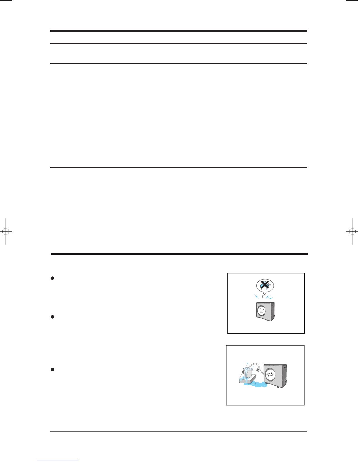
1-3 During operation
Do not repair the air conditioner at your discretion.
It is recommended to contact a service center directly.
Never spill any kind of liquid on the air conditioner.
If this happens, turn off the air conditioner and contact an authorized service center.
Do not spray any kind of liquid into the indoor unit. If this happens,
turn off the air conditioner and contact a service center.
1-1Samsung Electronics
1-5 Others
● Never store or load the air conditioner upside down or sideways to prevent the damage to the compressor.
● Young children or infirm persons should be always supervised when they use the air conditioner.
● Max current is measured according to IEC standard for safety.
● Current is measured according to ISO standard for energy efficiency.
1-4 Disposing of the unit
● Before throwing out the air conditioner, remove the batteries from the remote control.
● When you dispose of the air conditioner, consult your dealer. If pipes are removed incorrectly, refrigerant may blow out and
cause air pollution. When it contacts with your skin, it can cause skin injury.
● The package of the air conditioner should be recycled or disposed of properly for environmental reasons.
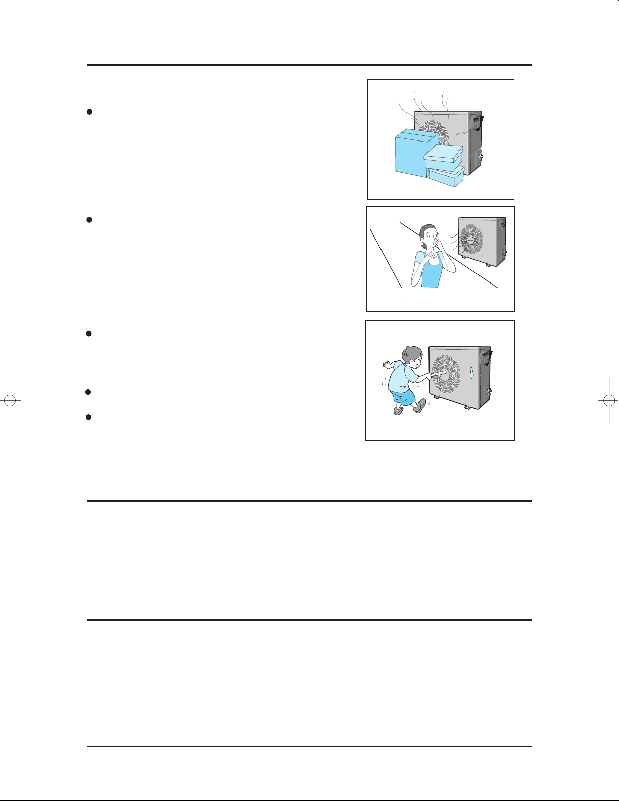
1-3 During operation(cont.)
Do not place any obstacles in front of the air conditioner.
Make sure that the air conditioner is well ventilated at all times:
Do not place a cloth or other materials over it.
Do not insert anything between the airflow blades to prevent damage
of the inner fan and consequent injury.
Keep children away from the air conditioner.
Remove the batteries if you don’t use the remote control
for a long time. (If applicable)
Use the remote control within 7 meters from the indoor unit.
(If applicable)
Samsung Electronics1-2

2. Product Specifications
2-1 The Feature of Product
■ Easier Installation
– Slim height and light weight
■ Easier Tuning
– Using phase control motor, Installers are able to optimize duct work & keep capacity and sound level as desired.
■ Various useful Functions
– Built in Drain Pump(Optional)
– Long piping
– • Maximum length : 50m
– • Maximum height : 30m
■ Convenient Control Functions
– Auto Change Over
– Central Controller(Optional) : Can Control up to 16 units individually
– Group Control
– Weekly program(Optional)
2-1Samsung Electronics
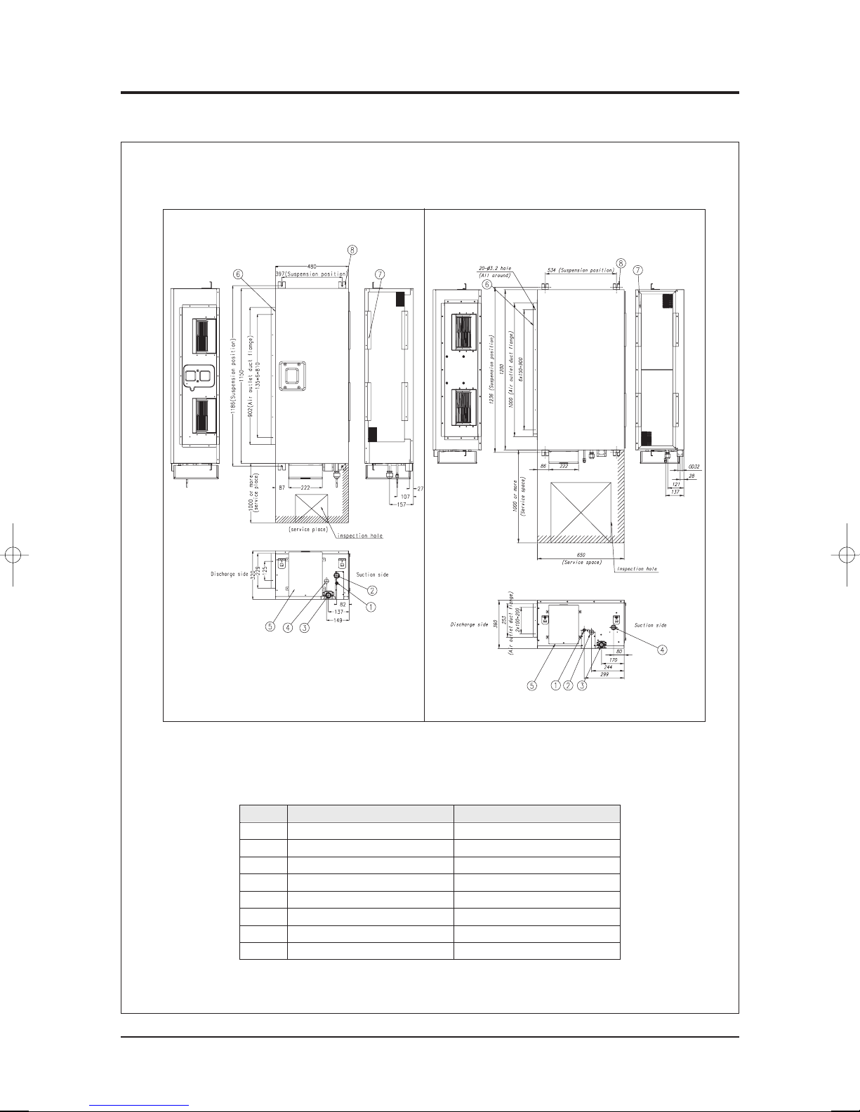
2-2 Name of Each Part
2-2-1 Indoor Unit
DH105EAMC DH140EAMC
(Unit : mm)
Number
1
2
3
4
5
6
7
8
Nam
e
Liquid pipe connection
Gas pipe connection
Drain pipe connection
Drain pipe connection
Power supply connection
Air discharge flange
Air filter
Hook
Description
ø9.52 Flare
ø19.05 Flare
OD32 ID26
Using drain pump (Optional)
For M8~M10
Samsung Electronics2-2
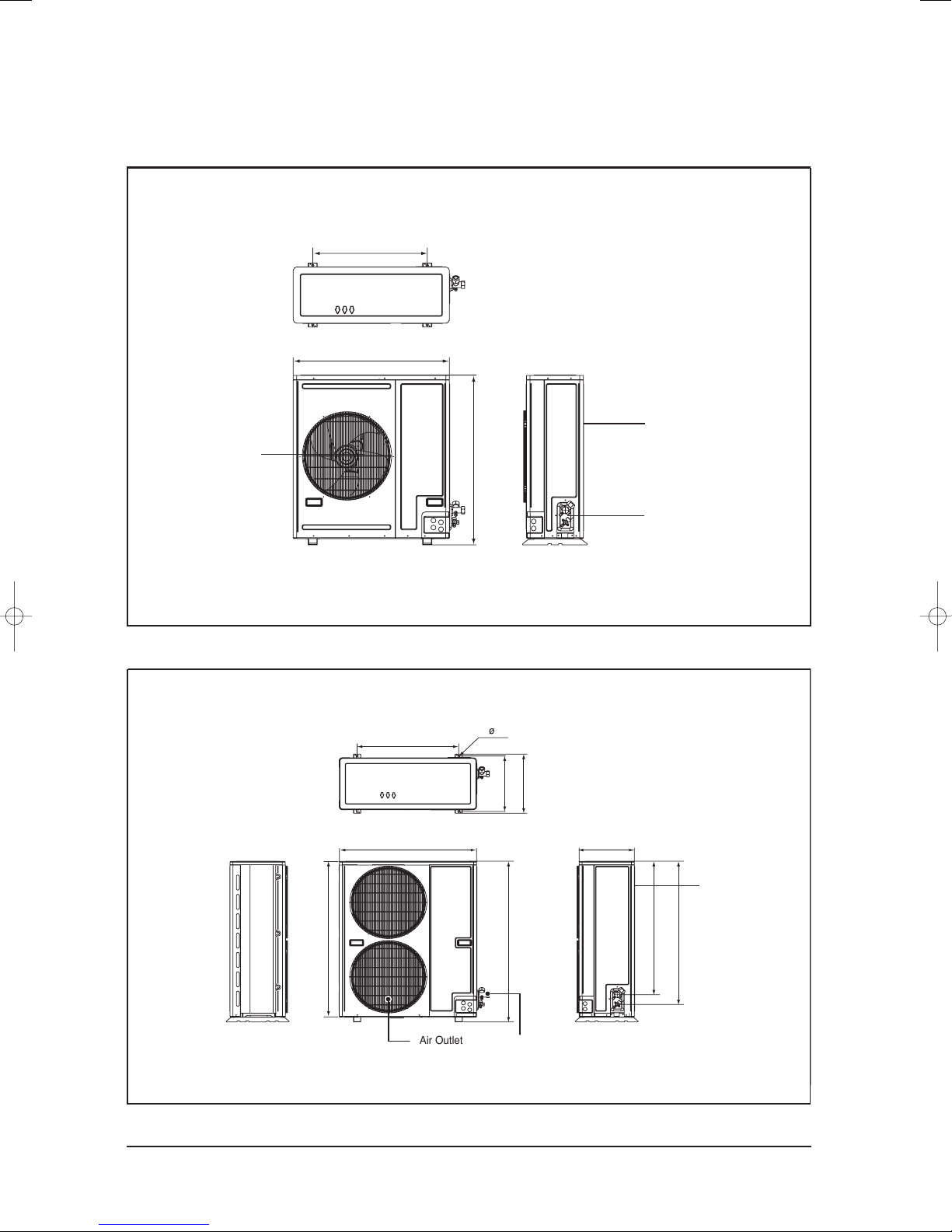
2-2-2 Outdoor Unit
Air Inlet(Rear)
Air Outlet
(Unit : mm)
645
880
0
59
690
932
375
82
1
,1
2
61
,
1
6
69
30
4
7
2
4
6
3
0
,
1
4- 12
Connection Valve
(1) UH105EAMC/UH105GAMC
Air Outlet
Production Specifications
(Unit : mm)
(Unit : mm)
Air Inlet(Rear)
Connection Valve
(2) UH140GAMC
2-3Samsung Electronics
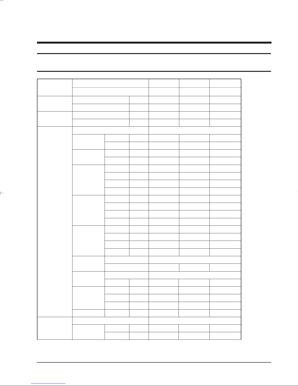
2-3. Product Specifications
Table
MODEL
Capacity
EER
Indoor Unit
Outdoor Unit
INDOOR UNIT
OUTDOOR UNIT
Cooling
Heating
Cooling
Heating
Power Supply
Power Input
Running Current
Fan Speed
Air Circulation
Noise Level
(Sound Pressure)
Heat Exchanger
Fan
Dimensions
Weight
Power Supply
Power Input
W
W
W/W
W/W
Type
Type
kW
kW
A
A
r.p.m
r.p.m
r.p.m
r.p.m
3
m
/min
3
m
/min
3
m
/min
3
m
/min
dB(A)
dB(A)
dB(A)
dB(A)
kW
mm
mm
mm
Net / Gross
kW
kW
Cooling
Heating
Cooling
Heating
Hi
Mid
Low
Ultra Low
Hi
Mid
Low
Ultra Low
Hi
Mid
Low
Ultra Low
Row x Stages x Fin Pitch
Motor Output
H
W
D
kg
Cooling
Heating
DH105EAMC
UH105GAMC
10,000
10,700
2.70
2.82
0.13
0.13
0.70
0.70
1180±50
1080±50
950±50
---
30
27
24
---
48
47
45
---
3x14x1.3
0.13
320
480
1150
39 / 46
3.7
3.8
DH140EAMC
UH140GAMC
14,700
16,000
2.67
2.81
220-240V~, 50Hz
0.22
0.22
1.40
1.40
950±50
900±50
820±50
---
38
34
30
---
51
49
47
---
Slit Fin Coil
Sirocco
0.22
360
650
1200
52 / 60
3ø, 380V~, 50Hz
5.5
5.7
DH105EAMC
UH105EAMC
10,000
11,000
2.58
2.86
0.13
0.13
0.70
0.70
1180±50
1080±50
950±50
---
30
27
24
---
48
47
45
---
3x14x1.33x16x1.3
0.13
320
480
1150
39 / 46
3.87
3.85
Samsung Electronics2-4
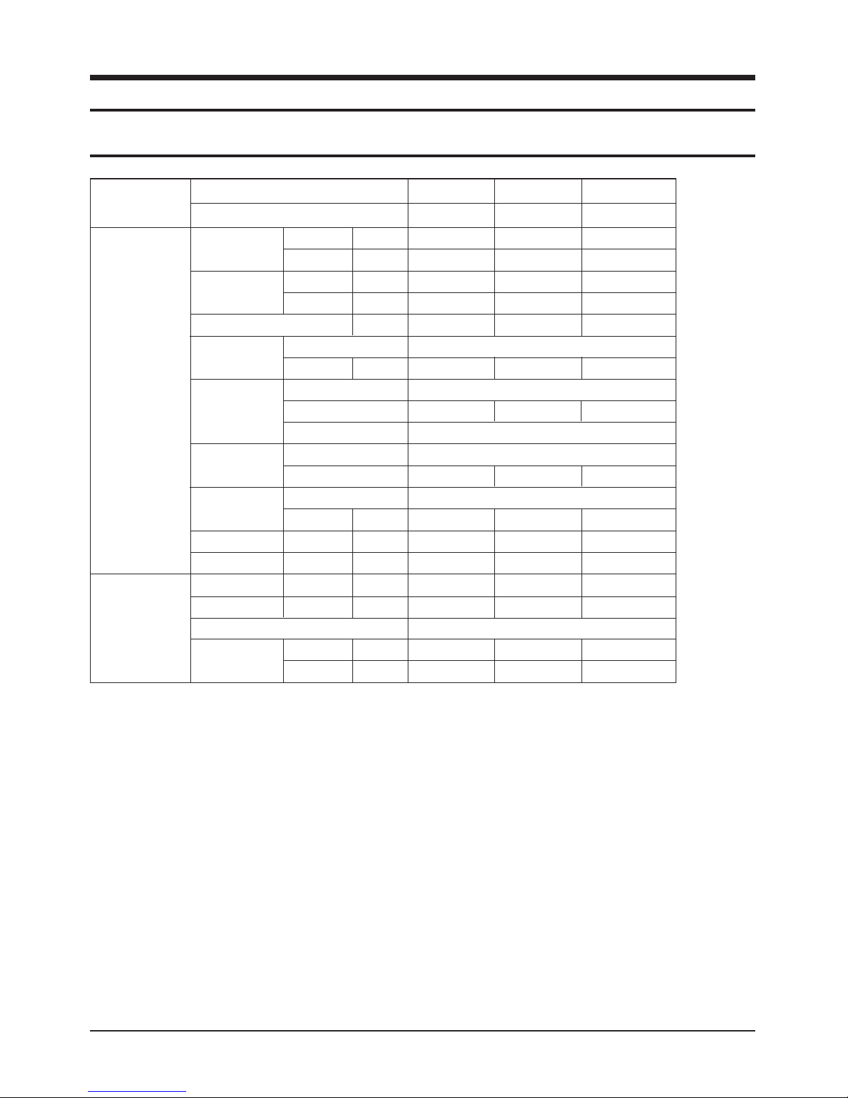
Table(cont.)
MODEL
Outdoor Unit
Piping
INDOOR UNIT
OUTDOOR UNIT
Current
Running
Fan Speed
Sound
Pressure Level
Fan
Compressor
Heat Exchanger
Refrigerant
Dimensions
Weight
Pipe O.D.
Size
Connection Method
Between
Cooling
Heating
Hi
Low
Type
Motor
Output
Type
Model
Protection
Type
Row x Stages x Fin Pitch
Control
(R22)Charge
(H x W x D)
kg
Liquid
Gas
Height
Pipe
Length
A
A
r.p.m.
r.p.m.
dB(A)
W
g
mm
Net /Gross
mm(inch)
mm(inch)
mm
mm
DH105EAMC
UH105GAMC
6.4
6.5
1080/1060±50
780/750±50
66
82
AN42YBFMT
2 x 42 x 1.3
2,750 3,300
880×931×320 880×931×320
87 / 92
9.52(3/8")
30
50
DH140EAMC
UH140GAMC
9.5
10.2
1020/990±50
600/550±50
67
Propeller
82
Scroll
BN62YFAMT
Internal
Slit fin coil
2 x 52x 1.5
EEV
932×1128×375
121 / 136
9.52(3/8")
19.05(3/4")19.05(3/4")
Flare
30
50
DH105EAMC
UH105EAMC
17.5
17.5
1080/1060±50
780/750±50
65
82
AN42VBFMT
2 x42 x 1.3
2,600
87 / 92
9.52(3/8")
19.05(3/4")
30
50
2-5Samsung Electronics
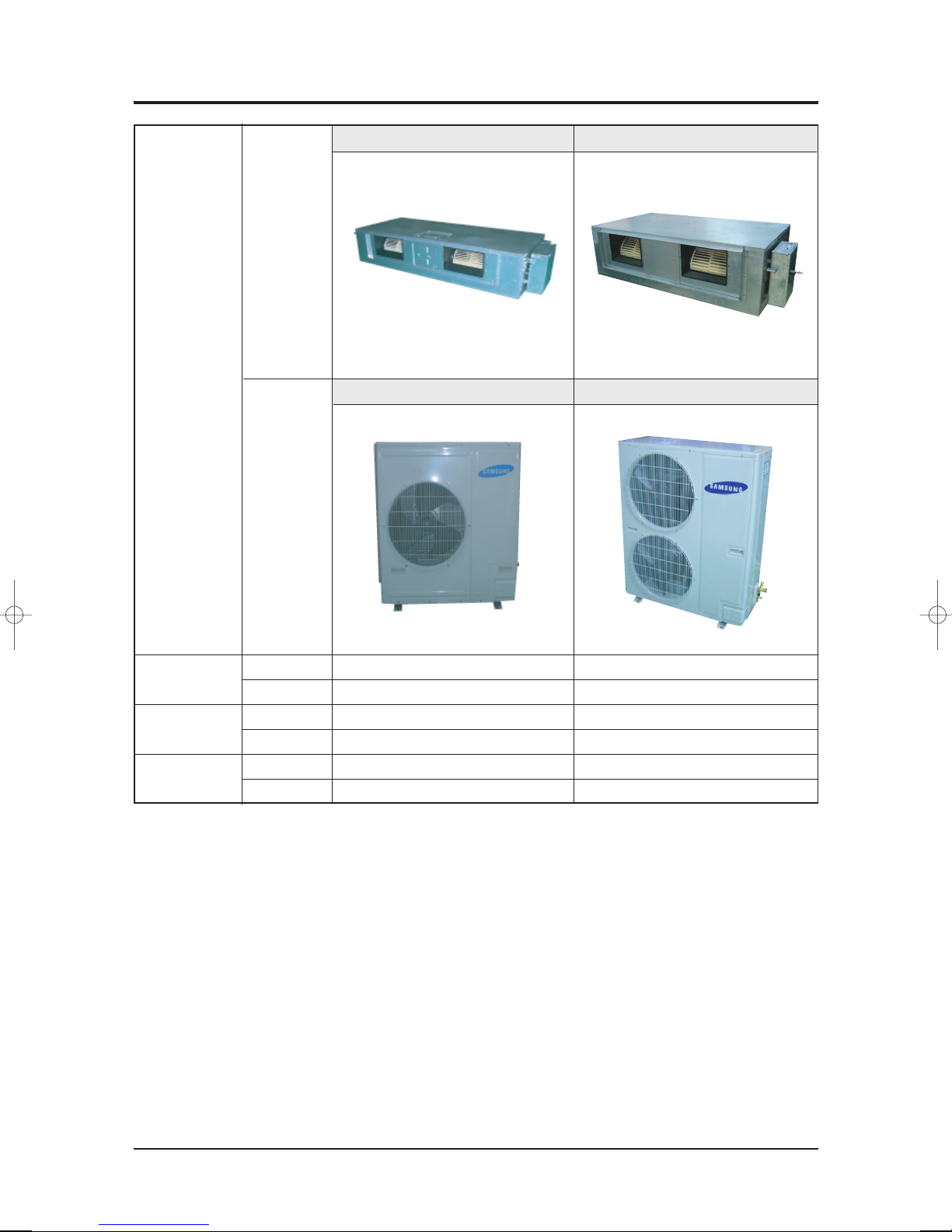
2-4 The Comparative Specifications of Product
DH105EAMC DH140EAMC
Indoor
Unit
Design
Net Weight
Outer Dimension
Noise
Outdoor
Unit
Indoor Unit
Outdoor Unit
Indoor Unit
Outdoor Unit
Indoor Unit
Outdoor Unit
UH105GAMC/UH105EAMC UH140GAMC
57.0kg
115.0kg
320 x 460 x 1150mm
880 x 931 x 320mm
48dB↓
66/65dB↓
52.0kg
136.0kg
360 x 650 x 1200mm
932 x 1128 x 375mm
51dB↓
67dB↓
Samsung Electronics2-6
2-5 Accessory and Option Specifications
O
W
N
E
R
'
S
I
N
S
T
R
U
C
T
I
O
N
S
M
A
N
U
A
L
D
E
I
N
S
T
R
U
C
C
I
O
N
E
S
I
ST
R
U
Z
I
O
N
I
P
E
R
L
'
U
S
O
M
A
N
U
A
L
D
E
I
N
S
T
R
U
Ç
Õ
E
S
M
A
N
U
E
L
D
'
U
T
I
L
I
S
A
T
I
O
N
G
E
B
R
A
U
C
H
S
A
N
W
E
I
S
U
N
G
S
p
l
u
t
-
t
y
p
e
R
o
o
m
A
i
r
C
o
n
d
i
t
i
o
n
e
r
A
i
r
e
a
c
o
n
d
i
c
i
o
n
a
d
o
d
o
m
é
s
t
i
c
o
s
i
s
t
e
m
a
S
p
l
i
t
C
o
n
d
i
z
i
o
n
a
t
o
r
e
d
'
a
r
i
a
p
e
r
a
m
b
i
e
n
t
i
a
d
u
n
i
t
à
S
e
p
a
r
a
t
e
A
p
a
r
e
l
h
o
d
e
a
r
c
o
n
d
i
c
i
o
n
a
d
o
t
i
p
o
S
p
l
i
t
C
l
i
m
a
t
i
s
e
u
r
d
e
t
y
p
e
s
é
p
a
r
é
G
e
t
e
i
l
t
e
r
a
u
m
k
l
i
m
a
a
n
l
a
g
e
O
W
N
E
R
'
S
I
N
S
T
R
U
C
T
I
O
N
S
M
A
N
U
A
L
D
E
I
N
S
T
R
U
C
C
I
O
N
E
S
I
S
T
R
U
Z
I
O
N
I
P
E
R
L
'
U
S
O
M
A
N
U
A
L
D
E
I
N
S
T
R
U
Ç
Õ
E
S
M
A
N
U
E
L
D
'
U
T
I
L
I
S
A
T
I
O
N
G
E
B
R
A
U
C
H
S
A
N
W
E
I
S
U
N
G
S
p
l
u
t
-
t
y
p
e
R
o
o
m
A
i
r
C
o
n
d
i
t
i
o
n
e
r
A
i
r
e
a
c
o
n
d
i
c
i
o
n
a
d
o
d
o
m
é
s
t
i
c
o
s
i
s
t
e
m
a
S
p
l
i
t
C
o
n
d
i
z
i
o
n
a
t
o
r
e
d
'
a
r
i
a
p
e
r
a
m
b
i
e
n
t
i
a
d
u
n
i
t
à
S
e
p
a
r
a
t
e
A
p
a
r
e
l
h
o
d
e
a
r
c
o
n
d
i
c
i
o
n
a
d
o
t
i
p
o
S
p
l
i
t
C
l
i
m
a
t
i
s
e
u
r
d
e
t
y
p
e
s
é
p
a
r
é
G
e
t
e
i
l
t
e
r
a
u
m
k
l
i
m
a
a
n
l
a
g
e
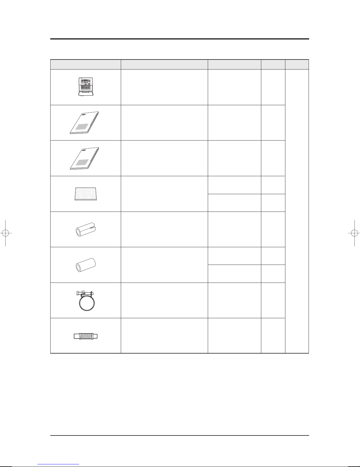
2-5-1 Accessories
Item Descriptions Q'TYCode-No. Remark
Wired remote controller DB97-01904G 1
Owner's Manual 1
Installation
Manual 1
DB98-26846A
DB98-26845
A
DB72-00143E 1
Insulation
DB62-01959
A 1
Insulation Drain In DB62-03440H 1
DB72-00143G 1
Insulation Install Inlet
DB72-00143
E 1
Indoor
Uni
t
Ass'y
Holder Drain Pipe DB90-02064A 1
Drain Hose Joint DB96-10453B 1
Ass'y
2-7Samsung Electronics
3. Alignment and Adjustments
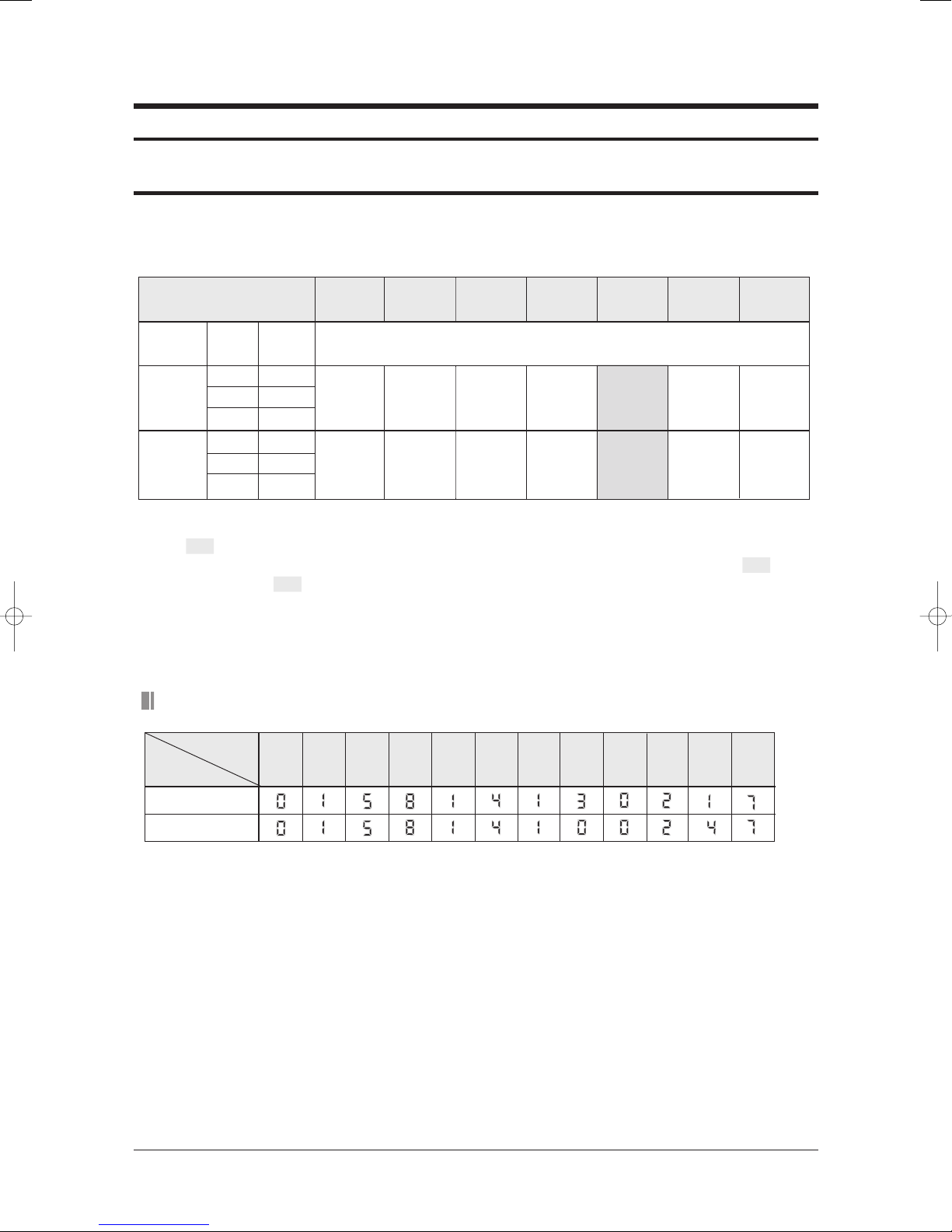
3-1 E. S. P(External Static Pressure) Setting for Phase Control Motor
With its phase control motor, you can adjust the indoor unit fan speed depending on the installation
condition. If the external static pressure is high so that the duct becomes longer or if the external static pressure is low so that the duct
becomes shorter, adjust the fan speed by referring the following table. Refer to the page 3-1 to set the option code.
Static Pressure(mmAq)
Hi
Hi
CMM
(CFM)
38(1341)
34(1200)
29.5(1041)
29.5(1041)
27(953)
24(847)
015813
-13018E
015814
-100091
015814
-1300A0
015814
-1000A2
Model
DH140EAMC
DH105EAMC
Note : • represents E. S. P(External Static Pressure) range of factory setting.
Step
Mid
Low
Mid
Low
You don't have to adjust the fan speed separately if the external static pressure of the installation place is in .
When it is out of , input the appropriate option code.
• If you input the inappropriate option code, error may occur or the air conditioner is out of order. The option code must be
inputted correctly by the installation specialist or service agent.
Option Code for Indoor Unit
015814
-1300C2
015814
-1000C3
015814
-1300E5
015814
-1000E5
-100247
015814
-130217
015814
1086420
015814
-130249
015814
-1002FC
Option items
Remote
Control
Model
SEG1 SEG2 SEG3 SEG4 SEG5 SEG6 SEG7 SEG8 SEG9 SEG10 SEG11 SEG12
15
015814
-1303E1
-
DH140EAMC
DH105EAMC
Samsung Electronics3-1
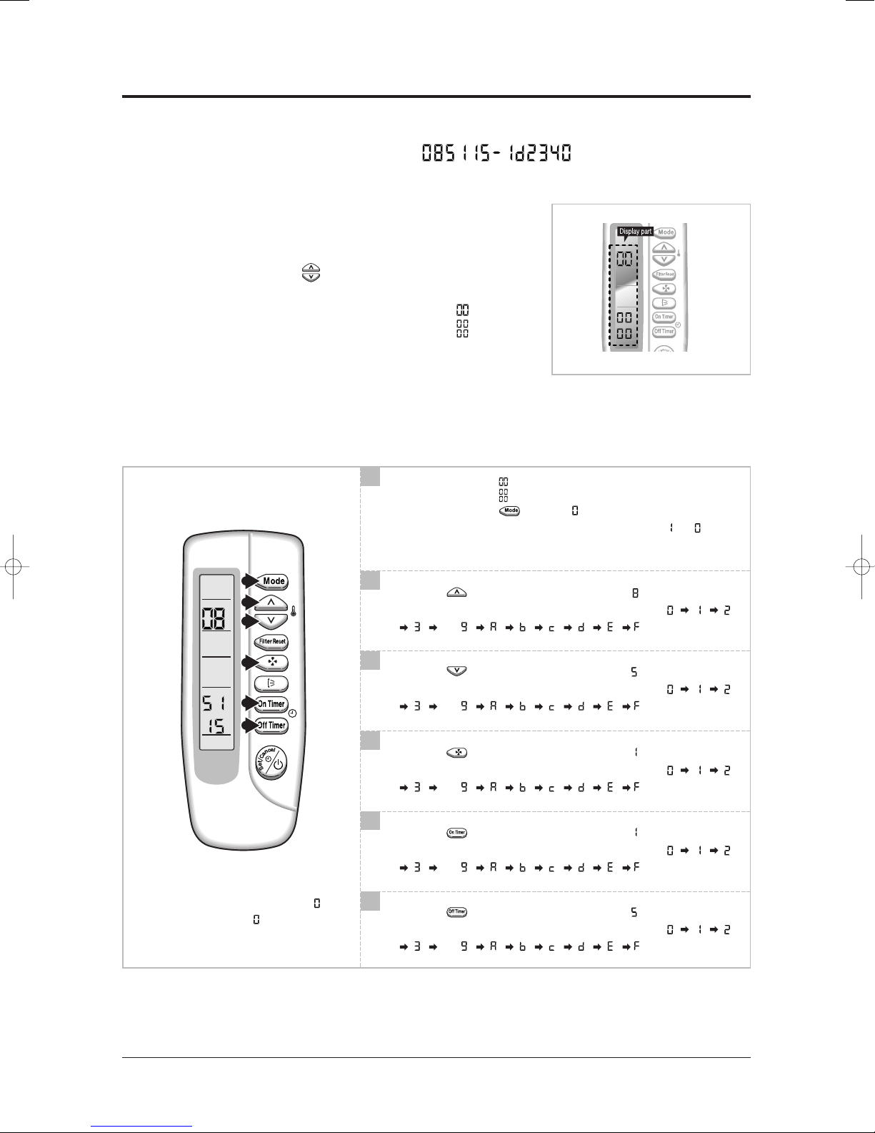
3-2 Setting Option Setup Method
ex) Option No. :
Step 1 : Enter the Option Setup mode.
st
1
2
3
Step 2 : Enter the Option Setup mode and select your option according to the following procedure.
Take out the batteries of remote control.
nd
Press the temp. button simultaneously and
insert the battery again.
rd
Make sure the remote control display shown as .
1
The default value is .
Otherwise, push the button to .
Every time you push the button, the display panel reads or
repeatedly.
1
2
3
4
5
6
✳ Setting is not required if you must
a value which has a default.
2
Push the button to set the display panel to .
Every time you push the button, the display panel reads
. . .
3
Push the button to set the display panel to .
Every time you push the button, the display panel reads
. . .
4
Push the button to set the display panel to .
Every time you push the button, the display panel reads
. . .
5
Push the button to set the display panel to .
Every time you push the button, the display panel reads
. . .
6
Push the button to set the display panel to .
Every time you push the button, the display panel reads
. . .
repeatedly.
repeatedly.
repeatedly.
repeatedly.
repeatedly.
3-2Samsung Electronics
Alignment and Adjustments
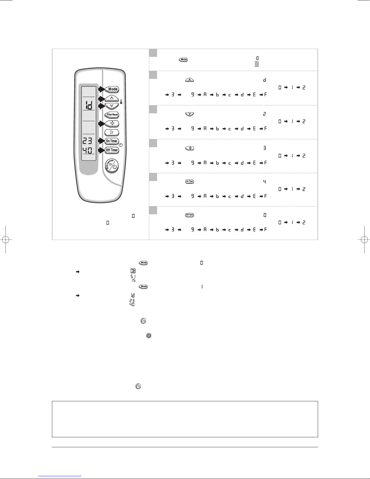
7
8
9
10
7
Press button, then the default value is .
8
Push the button to set the display panel to .
Every time you push the button, the display panel reads
. . .
9
Push the button to set the display panel to .
Every time you push the button, the display panel reads
. . .
repeatedly.
repeatedly.
11
12
10
Push the button to set the display panel to .
Every time you push the button, the display panel reads
. . .
11
Push the button to set the display panel to .
Every time you push the button, the display panel reads
. . .
12
✳ Setting is not required if you must
a value which has a default.
Push the button to set the display panel to .
Every time you push the button, the display panel reads
. . .
Step 3 : Upon completion of the selection, check you made right selections.
Press the Mode Selection key, to set the display part to and check the display part.
The display part shows .
Press the Mode Selection key, to set the display part to and check the display part.
The display part shows .
repeatedly.
repeatedly.
repeatedly.
Step 4 : Pressing the ON/OFF button ( )
When pressing the operation ON/OFF key with the direction of remote control for unit, the sound ''Ding'' or ''Diriring'' is
heard and the OPERATION ICON( ) lamp of the display is flickering at the same time, then the input of option is completed. (If the diriring sound isn't heard, try again pressing the ON/OFF button.)
Step 5 : Unit operation test-run
First, Remove the battery from the remote control.
Second, Re-insert the battery into the remote control.
Third, Press ON/OFF button( ) with the direction of remote control for set.
• Error Mode
st
1
If all lamps of indoor unit are flickering, Plug out, plug in power plug again and press ON/OFF key to retry.
2ndIf the unit is not working properly or all lamps are continuously flickering after setting the option code, see if the correct option code
is set up for its model.
Samsung Electronics3-3
4-1Samsung Electronics
4. Disassembly and Reassembly
Stop operation of the air conditioner and remove the power cord before repairing the unit.
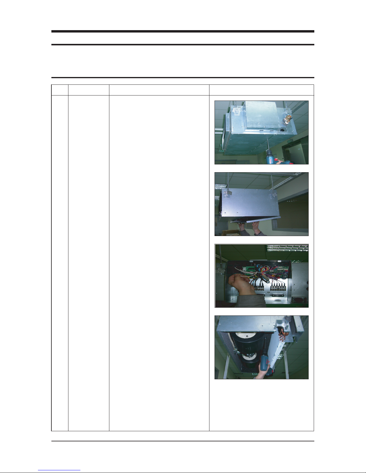
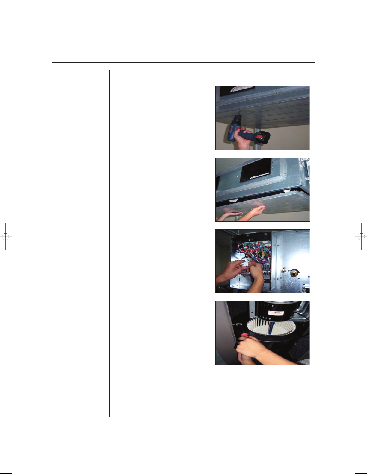
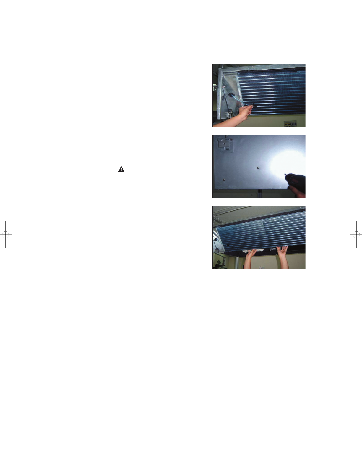
4-1 Indoor Unit
No Parts Procedure Remark
1 Blower & Motor
1)
After disassembling 16 places indicating
screws,
detach Ass'y Cabi Bottom Blower.
2)
Detach from Ass'y Control In the
capacitor
connection wire between the
Motor Fan and housing connector.
3) After disassembling 2 places indicating
screws,
detach the 2 Fan Case.
(DH105EAMC)
Samsung Electronics4-2
Disassembly and Reassembly
No Parts Procedure
Remark
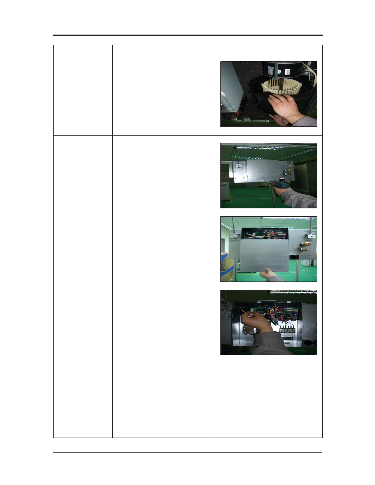
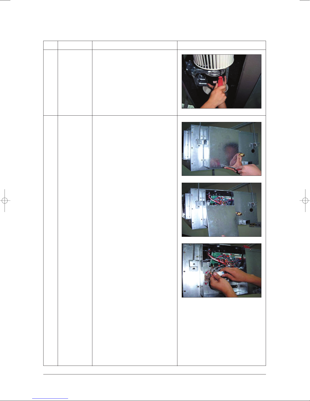
2 Control In
4) After disassembling 2 places indicating
screws, detach Fan Motor and Blower
from the set.
1) After disassembling 1 Indicating screw,
detach the Cover control.
2) Detach the Motor-Fan and Sensor
Connector from the PCB.
4-3Samsung Electronics
Disassembly and Reassembly
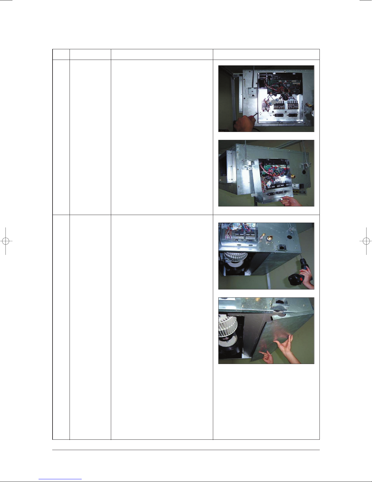
No Parts Procedure Remark
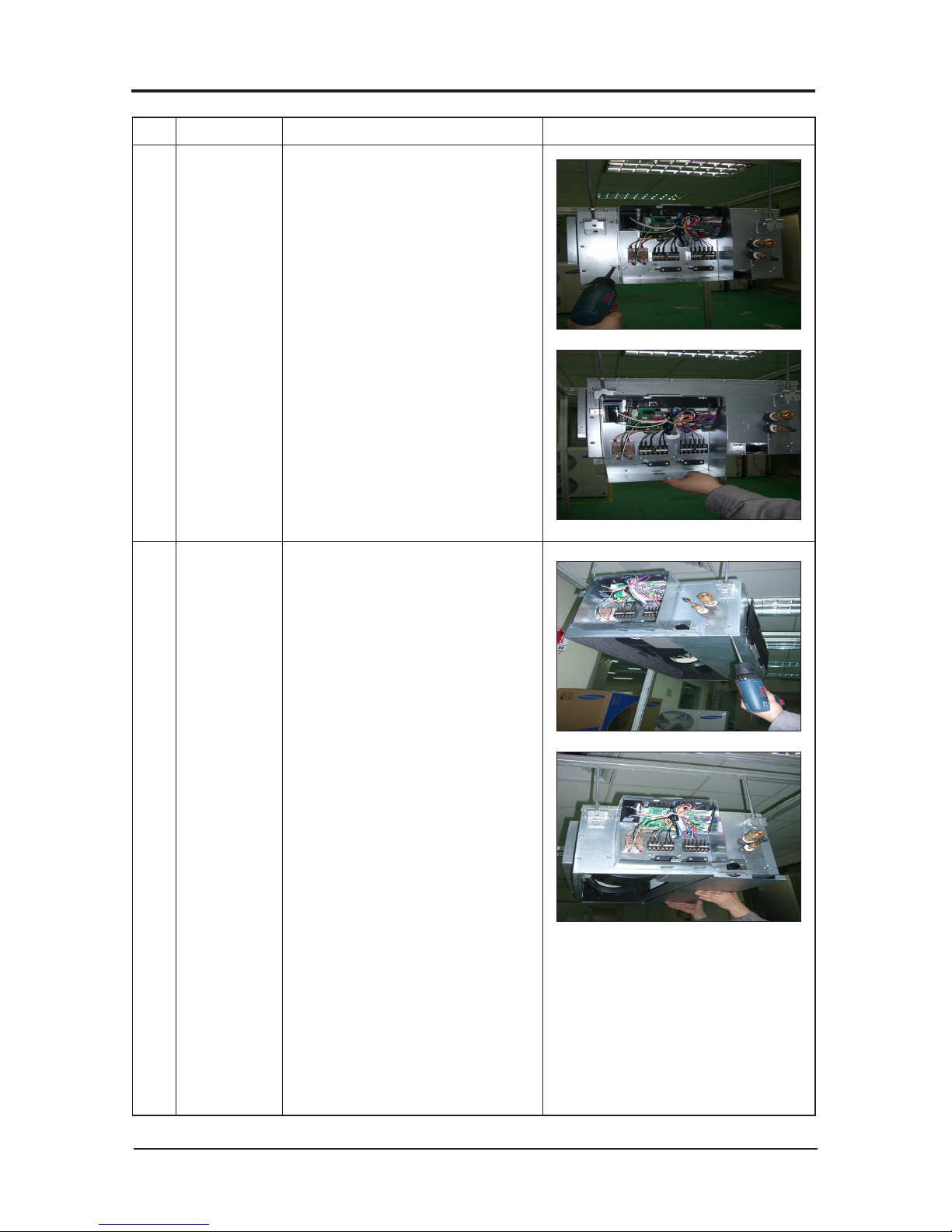
3 Drain Pan
3) Disassemble 4 indicating screws and
detach Control In from the set.
Work is possible when Disassembling the
Ass'y Cabi Bottom Blower.
1) Disassemble 7 indicating screws and
detach Ass'y Cabi Bottom Drain.
Samsung Electronics4-4
Disassembly and Reassembly
No Parts Procedure Remark
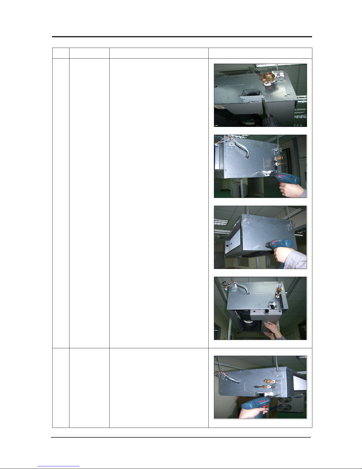
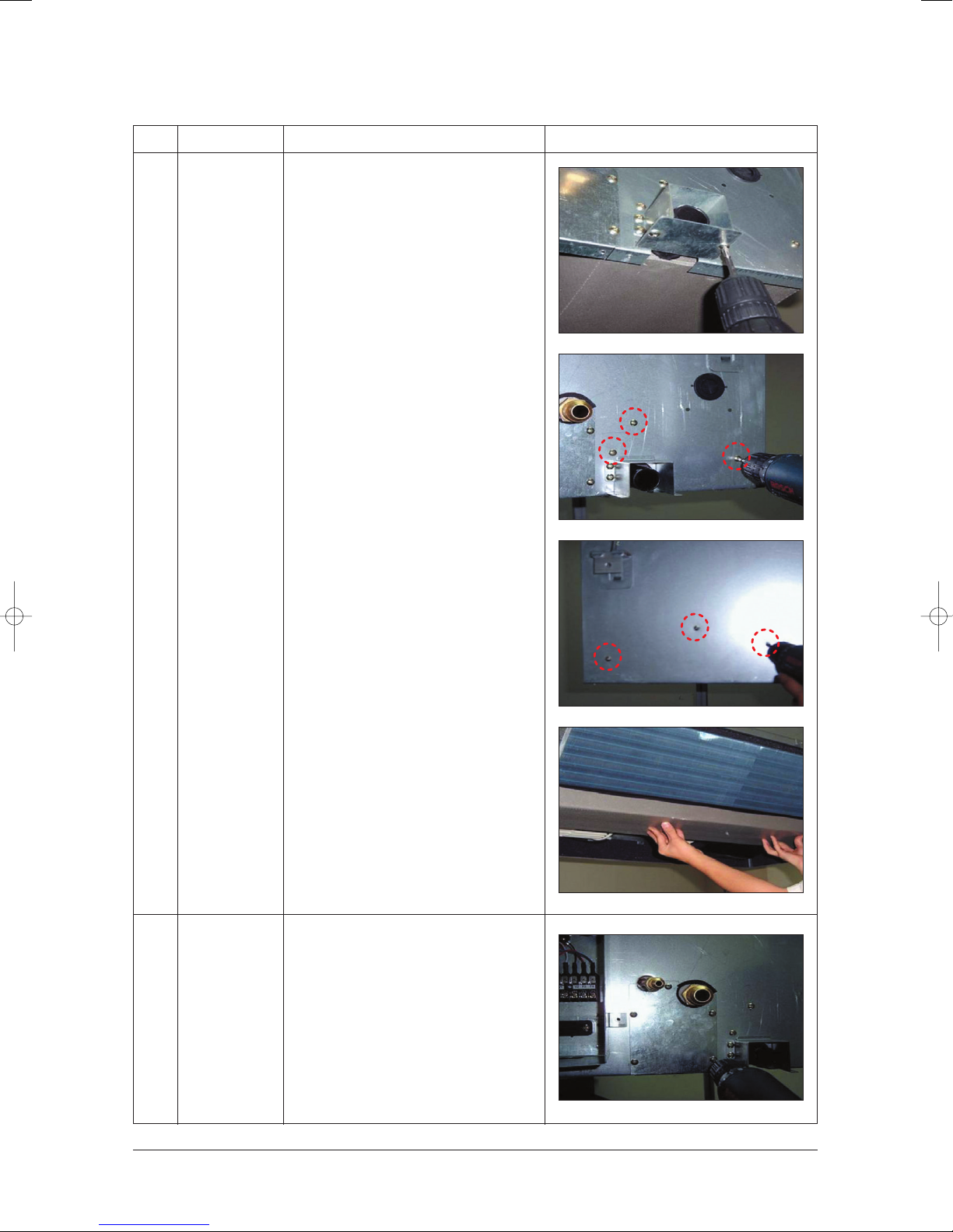
4
Evap
2) Disassemble 2 indicating
screws and detach Holder Pipe.
3) Disassemble 4 indicating screws and
detach the Drain Pan.
(2 screws each at left and right side)
Work is possible when Disassembling
the Ass'y Drain Pan.
1) Disassemble 5 indicating screws to
detach Cover Pipe.

4-5Samsung Electronics
Disassembly and Reassembly
No Parts Procedure Remark
2) Disassemble Sensor on the Evap.
3) Disassemble 4 indicating screws which
are in the near of Hanger Plate to detach
the Evap.
(2 screws each at left and right side)
It needs 2 peoples.
Disassembly and Reassembly
Indoor Unit (DH140EAMC)
No Parts Procedure Remark
1 Blower & Motor
1) After disassembling 15 places indicating
screws, detach Ass'y Cabi Bottom Blower.
2) Detach from Ass'y Control In the
capacitor connection wire between the
Motor Fan and housing connector.
3) After disassembling 4 places indicating
screws, detach the 2 Fan Case.
Samsung Electronics4-6
Disassembly and Reassembly
No Parts Procedure Remark
4) After disassembling 2 places indicating
screws, detach Fan Motor and Blower
from the set.
2 Control In
1) After disassembling 1 Indicating screw,
detach the Cover control.
2) Detach the Motor-Fan and Sensor
Connector from the PCB.
4-7Samsung Electronics
Disassembly and Reassembly
No Parts Procedure Remark
3) Disassemble 4 indicating screws and
detach Control In from the set.
3 Drain Pan
✳ Work is possible when Disassembling the
Ass'y Cabi Bottom Blower.
1) Disassemble 6 indicating screws and
detach Ass'y Cabi Bottom Drain.
Samsung Electronics4-8
Disassembly and Reassembly
No Parts Procedure Remark
2) Disassemble 2 indicating
screws and detach Holder Pipe.
3) Disassemble 6 indicating screws and
detach the Drain Pan.
(3 screws each at left and right side)
4
Evap
✳ Work is possible when Disassembling
the Ass'y Drain Pan.
1) Disassemble 5 indicating screws to
detach Cover Pipe.
4-9Samsung Electronics
Disassembly and Reassembly
No Parts Procedure Remark
2) Disassemble Sensor on the Evap.
3) Disassemble 2 indicating screws which
are in the near of Hanger Plate to detach
the Evap.
(1 screw each at left and right side)
It needs 2 peoples.
Samsung Electronics4-10
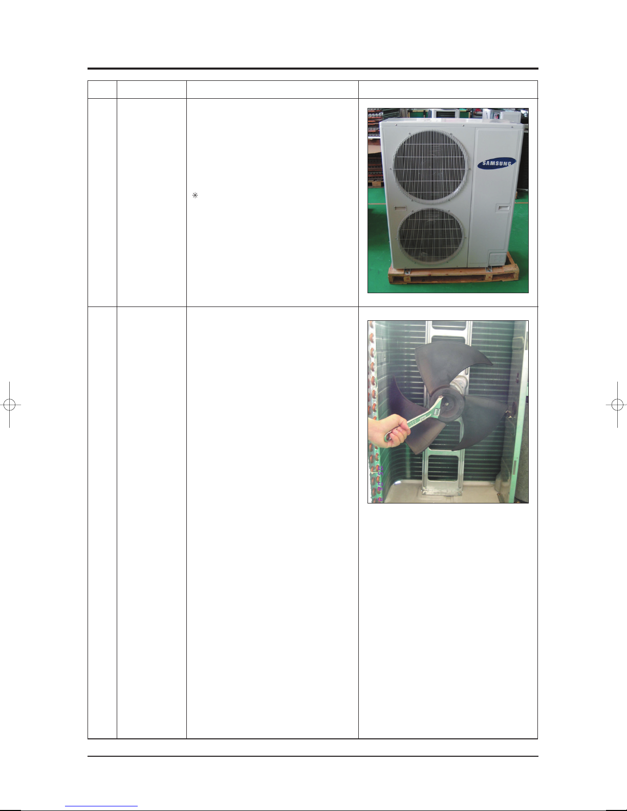
4-2 Outdoor Unit (UH140GAMC)
No Parts Procedure Remark
1
2
Cabinet
Fan Motor
&
Propeller Fan
1) Turn off the equipment and disassemble
the
power cable.
2) Uncover the Top Cover.
3) Uncover the Control Box Cover.
4) Pull out the assemble Cable.
5) Disassemble the Cabinet Side.
6) Disassemble the Cabinet Front.
Check if each part is fixed to the
connector firmly at the time of
electric
part
assembly.
1) Loosen the Propeller Fan Bolt.
2) Disassemble the Fan.
4-11Samsung Electronics
Disassembly and Reassembly
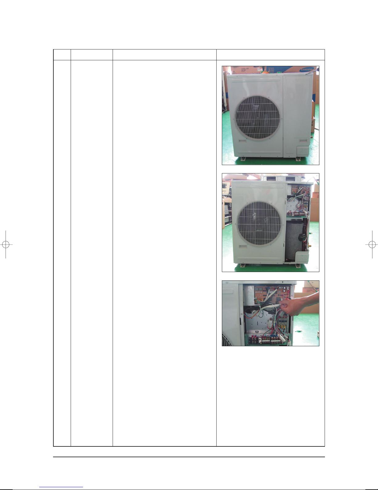
Outdoor Unit (UH105GAMC/UH105EAMC)
No Parts Procedure Remark
3 Control Box
&
PCB
1) Loosen the 8 screws fixing the Cover
Side.
2) Loosen the screws and push the
Cover
Side in the arrow direction for
disassembly.
3) Disconnect the PCB connector and
disassembly
the Electronic Box and PCB.
Samsung Electronics4-12

Samsung Electronics
MEMO
4-13
Samsung Electronics
5-1
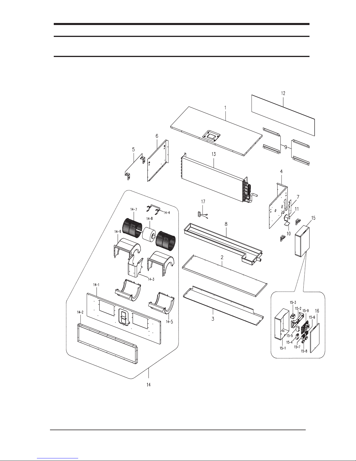
5. Exploded Views and Parts List
5-1 Indoor Unit
DH105EAMC
 Loading...