

Samsung Blu-ray HT-J4500, Blu-ray HT-J4530, HT-J4500 Quick Installation Manual
1-
English
2-
English
3-
English
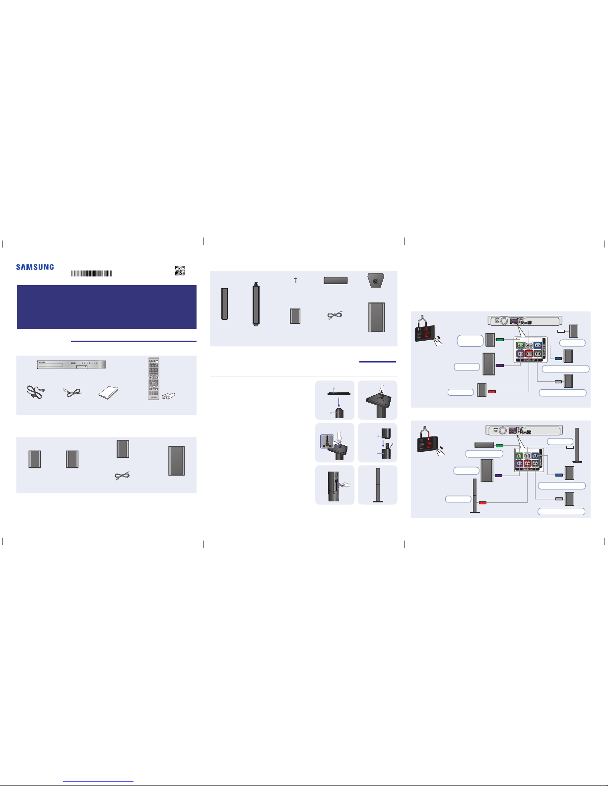
1 Unpacking
Accessories
TOOLS
RETURN
EXIT
INFO
SUBTITLE HOME REPEAT
123
7
89
DISC MENU TITLE MENU
0
POPUP
4
56
MUTE
MO/ST
TUNER
MEMORY
ABCD
TUNING
DOWN
UP
VOLUME
-
+
DSP/EQTV SOUND
FUNCTION
Main Unit
Power Cable FM Antenna User Manual Remote Control / Batteries (AAA size)
Speaker Components
HT-J4500
Center
Front x 2 Surround x 2 Speaker Cable x 6 Subwoofer
HT-J4500/HT-J4530
Quick Installation Guide
5.1CH Blu-ray™ Home Entertainment System
AH68-02796L-02
AH68-02796L-02
HT-J4530
Screw (5x20) x 8 Center Stand Base x 2
Front x 2 Stand x 2 Surround x 2 Speaker Cable x 6 Subwoofer
2 Installing and Connecting the Speakers
Installing the Speakers on the Tallboy Stand
* HT-J4530 only - Front Speakers
1 Turn the Stand Base upside-down and connect it to the
Stand.
2 Use the driver to combine the screws on the
3 marked holes.
3 Straighten a supplied speaker wire to the gravity
direction and put in the hole on the center of Stand
Base.
4 Connect the upper Speaker to the assembled Stand.
5 Insert a screw clockwise into the hole on the rear of the
speaker using a screwdriver.
And then connect a speaker cable.
6 This is the appearance after the speaker is installed.
Follow this steps to install other speaker.
Stand Base
Stand
Speaker
Stand
Speaker Cable Connections
1 Match each speaker cable bundle to the correct speaker by matching the colored band on each bundle
to the colored sticker on the bottom of each speaker.
2 Connect the speaker wire plugs from each speaker to the back of the product by matching the colored
band on each cable to the colors of the speaker jacks. When connecting, make sure to match label
color on the back of speaker.
HT-J4500
SURROUND
SURROUND
S
URROUND
SURROU
ND
SURROUND
SURROUND
Center
Speaker
Surround Speaker (R)
Surround Speaker (L)
Subwoofer
Front (L)
Front (R)
Back of the
speakers.
Match polarity.
HT-J4530
SURROUND
SURROUND
SURROUND
SURROUN
D
SURROUND
SURROUND
Center Speaker
Surround Speaker (R)
Surround Speaker (L)
Subwoofer
Front (L)
Front (R)
Back of the
speakers.
Match polarity.
4-
English
5-
English
6-
English
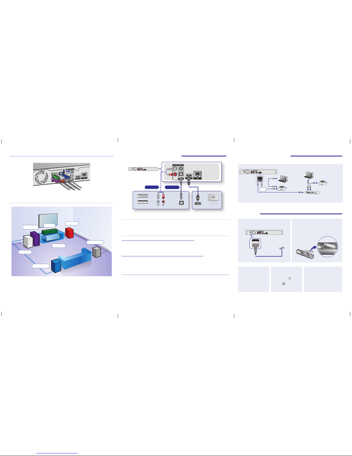
Connecting the Speakers
The speakers, speaker cables, and speaker jacks are color coded and must match.
SURROUND
SURROUND
✎
Match each speaker cable plug to the correct speaker jack on the back of the home theater main unit by
color, and then insert the plug.
Speaker Placement
Front (L)
Front (R)
Surround (R)
Subwoofer
Surround (L)
Center
Product
✎
The appearance of your speakers may differ from the illustrations in this guide.
✎
Each speaker has a colored label on its back or underside. Each cable has a single colored band near
its end. Match the band on each cable to the speaker label by color, and then connect the cable to the
speaker.
3 Connecting the Main Unit
HDMI IN (ARC)
OPTICAL OUT
AUDIO OUT
SURROUND
SURROUND
External Devices
Method 1
Method 2
Connecting to a TV
Connect an HDMI cable (not supplied) from the HDMI OUT jack on the back of the product to the HDMI IN jack
on your TV. If the TV supports ARC, you can hear the audio from your TV through the home theater with only this
cable connected.
Connecting to External Devices
Method 1 AUX IN : Connecting an External Analog Component
Using an RCA audio cable (not supplied), connect the AUDIO In jack on the product to the AUDIO Out jack on
the external analog component. Select the AUX mode.
• Be sure to match the colors on the cable plugs to the colors on the input and output jacks.
Method 2 OPTICAL : Connecting an External Digital Audio Component
Use to connect the digital audio output of digital signal components such as Cable Boxes and Satellite Receivers
(Set-Top-Boxes) to the home theater. Using a digital optical cable (not supplied), connect the Optical Digital
Audio In jack on the product to the Digital Optical Out jack of the external digital device using a digital optical
cable. Select the D. IN mode.
Selecting an External Device to Use
To select an external device after you have connected it, press the FUNCTION button. Each time you press the
button, the mode changes in this order : BD/DVD D. IN AUX FM BT
4 Network Connections
You can connect your product to your network router using a method illustrated below.
SURROUND
SURROUND
Broadband
service
Broadband
service
Broadband modem
Router
Broadband modem (with integrated router)
OR
✎
Use Cat 7 (*STP Type) cable for the connection. (* Shielded Twisted Pair)
5 Using
3 Turn on the TV.
Turn on the TV with the
TV’s remote control.
4 Turn on the home
theater.
Press Power
on the
front panel or press the
Power
on the remote
control.
5 Configure the initial settings.
When you turn on the home
theater for the first time, the initial
set up screens appear. Follow
the instructions on the screens to
perform the initial set up.
2 Insert batteries into the remote control.
Insert 2 AAA sized batteries into the battery
compartment of the remote control.
1 Connect the power cable to the main unit.
SURROUND
SURROUND
POWER
 Loading...