

Samsung Duct Type Series, BIG duct AM FNHDCH Series Installation Manual

Duct Type Series
BIG duct : AM✴✴✴FNHDCH✴
Air Conditioner
installation manual
imagine the possibilities
Thank you for purchasing this Samsung product.

Contents
Safety Precautions . . . . . . . . . . . . . . . . . . . . . . . . . . . . . . . . . . . . . . . . . . . . . . . . . . . . . . . . . . . . . . . . . . . . . . . . . . . . . . . . . . . . . . . . . . . . . . . . . . . . . . . 3
Accessories .............................................................................................................. 5
Selecting the Installation Location ....................................................................................... 6
Indoor Unit Installation .................................................................................................. 9
Purging the Unit ........................................................................................................ 10
Connecting the Refrigerant Pipe ........................................................................................ 10
Cutting/Flaring the Pipes ................................................................................................ 11
Performing leak test & insulation ........................................................................................ 12
Drain pipe and drain hose installation ................................................................................... 15
Wiring work ............................................................................................................ 19
Setting an indoor unit address and installation option ................................................................... 23
Setting temperature control of discharge air ............................................................................ 36
Final Checks and User Tips .............................................................................................. 36
Troubleshooting ........................................................................................................ 37
Option table ............................................................................................................ 39
2
Safety Precautions
WARNING
• Cancer and Reproductive Harm - www.P65Warnings.ca.gov.
The following safety precautions must be taken when using your air conditioner.
• Risk of electric shock can cause injury or death.
WARNING
• Disconnect all remote electric power supplies before servicing, installing or cleaning.
• Installation must be done by the manufacturer or service agent or a similar qualied
person in order to avoid a hazard.
Installing the unit
f The unit should not be installed by the user. Ask the dealer or authorized company to install the units
f If the unit is installed improperly, water leakage, electric shock or re may result.
f Mount with the lowest moving parts at least 2.5 m (8.2 ft) above the oor or grade level. (If applicable)
f The manufacturer does not assume responsibility for accidents or injury caused by an incorrectly installed air conditioner.
If you are unsure about installation, contact an installation specialist.
f When installing the built-in type air conditioner, keep all electrical cables such as the power cable and the connection
cord in pipe, ducts, cable channels e.t.c to protect them against liquids, outside impacts and so on. The air conditioner
should be used only for the applications for which it has been designed: the indoor unit is not suitable to be installed in
areas used for laundry.
f This appliance is not accessible to the general public. This appliance should be installed according to the provided
installation instruction.
f When installing the air conditioner in a small room, the measure not to exceed the dangerous density is needed.
- When refrigerant leaks and exceeds the dangerous density, suocation may occur.
f If any gas or impurities except R-410A refrigerant come into the refrigerant pipe, serious problem may occur and it may
cause injury.
f Use only rated accessories and install the air conditioner with rated equipments.
- If you dont’t use the rated accessories, the air conditioner may drop from its place, water may leak or electric shock or
re may occur.
f Ventilate your room when refrigerant gas leaks during installation.
- Toxic gas may generate when refrigerant gas contacts with heat.
f Our units must be installed in compliance with the spaces indicated in the installation manual to ensure either
accessibility from both sides or ability to perform routine maintenance and repairs. The units’ components must be
accessible and that can be disassembled in conditions of complete safety either for people or things.
For this reason, where it is not observed as indicated into the Installation Manual, the cost necessary to reach and repair
the unit (in safety, as required by current regulations in force) with slings, trucks, scaolding or any other means of
elevation won’t be considered in-warranty and charged to end user.
f This unit is intended for free-air discharge or for connection to a duct supplying only one room.
ENGLISH
3
Safety precautions
Power supply line or circuit breaker
f If the power cable of this air conditioner is damaged, it must be replaced by service agent or similarly qualied persons in
order to avoid a hazard.
f The unit must be plugged into an independent circuit if applicable or connect the power cable to the auxiliary circuit
breaker. An all pole disconnection from the power supply must be incorporated in the xed wiring with a contact
opening of >3 mm (0.12 inch).
f The air conditioner must be installed in accordance with national wiring regulations and safety regulations wherever
applicable.
f The electric work must be done by service agent or similarly qualied persons according to national wiring regulations
and use only rated cable.
- If the capacity of the power cable is insucient or electric work is not properly completed, electric shock or re may
occur.
f Install the cables with supplied cables rmly. Fix them securely so that external force is not exerted to the terminal board.
- If the connection or xing is incomplete, heat generation, electric shock or re may occur.
f Connect the power cable between the indoor and outdoor unit properly so that the electrical component box cover is
not get loosen and attach the cover securely.
- If the the cover is attached incompletely, heat generation, electric shock or re of the terminal board may occur.
f Be sure not to perform power cable modication, extension wiring, and multiple wire connection.
- It may cause electric shock or re due to poor connection, poor insulation, or current limit override.
- When extension wiring is required due to power line damage, refer to “How to connect your extended power cables” in
the installation manual.
• Make sure that you earth the cables.
CAUTION
- Do not connect the ear th wire to the gas pipe, water pipe, lighting rod or telephone wire. If earthing is not
complete, electric shock or re may occur.
• Install the circuit breaker.
- If the circuit breaker is not installed, electric shock or re may occur.
• Make sure that the condensed water dripping from the drain hose runs out properly and safely.
• Install the power cable and communication cable of the indoor and outdoor unit at least 1 m (3.28 ft) away from
the electric appliance.
• Install the indoor unit away from lighting apparatus using the ballast.
- If you use the wireless remote control, reception error may occur due to the ballast of the lighting apparatus.
• Do not install the air conditioner in following places.
- Place where there is mineral oil or arsenic acid. Resin parts ame and the accessories may drop or water may
leak. The capacity of the heat exchanger may reduce or the air conditioner may be out of order.
- The place where corrosive gas such as sulfurous acid gas generates from the vent pipe or air outlet. The copper
pipe or connection pipe may corrode and refrigerant may leak.
- The place where there is a machine that generates electromagnetic waves. The air conditioner may not
operate normally due to control system.
- The place where there is a danger of existing combustible gas, carbon ber or ammable dust. The place
where thinner or gasoline is handled. Gas may leak and it may cause re.
4
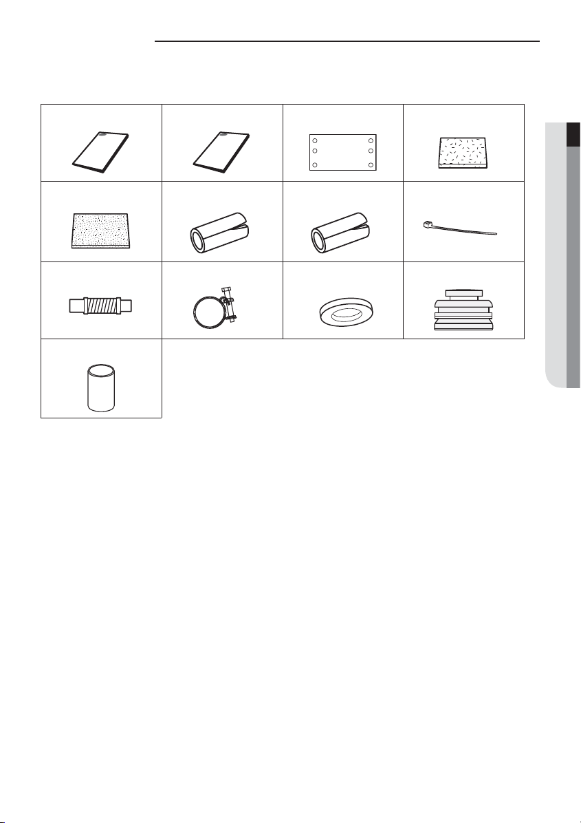
Accessories
The following accessories are supplied with the indoor unit.
The type and quantity may dier depending on the specications.
User's manual Installation manual Pattern sheet Insulation cover pipe in
Insulation cover pipe out Pipe insulation (A) Pipe insulation (B) Cable tie
Flexible hose Clamp hose Washer Rubber
Sleeve
ENGLISH
5

Selecting the Installation Location
Indoor Unit
f There must be no obstacles near the air inlet and outlet.
f Install the indoor unit on a ceiling that can support its weight.
f Maintain sucient clearance around the indoor unit.
f Make sure that the water dripping from the drain hose runs away correctly and safely.
f The indoor unit must be installed in this way, that they are out of public access. (Not touchable by the users)
f After connecting a chamber, insulate the connection part between the indoor unit and the chamber with t10 mm(3/8")
or thicker insulation. Otherwise, there can be air leak or dew from the connection part.
f Rigid wall without vibration.
f Where it is not exposed to direct sunshine.
f Where the air lter can be removed and cleaned easily.
Space requirements for installation & service
Unit Width(W)
Unit Depth(D)+50 mm (1.97 inch)
“A”=W+100 mm(3.94 inch)
“B”=500 mm(19.69 inch)
20 mm(0.79 inch) or more
20 mm(0.79 inch) or more
f You must have 20 mm(0.79 inch) or more space between the ceiling and the bottom of indoor unit. Otherwise, the noise
from the vibration of indoor unit may bother the user. When the ceiling is under construction, the hole for check-up must
be made to take service, clean and repair the unit.
f It is possible to install the unit at an height of between 2.2(7.22 ft) ~ 2.5 m(8.20 ft) from the ground, if the unit has a duct
with a well dened lenght[300 mm(0.98 ft) or more], to avoid fan motor blower contact.
6
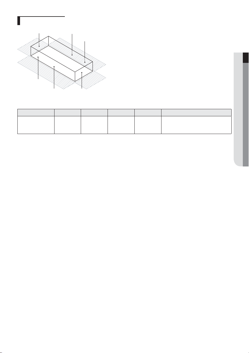
Insulation Guide
D
Front
Front
A
Thickness: more than 10 mm(0.39inch)
Indoor Unit A B C D Front/Back
1240x470x1040
(48.8x18.5x40.9)
f Insulate the end of the pipe and some curved area by using separate insulation.
f Insulate the discharge and suction part at the same time when you insulate connection duct.
400x190
(15.7x7.5)
B
Back
Back
C
1240x1040
(48.8x40.9)
470x1040
(18.5x40.9)
470x1040
(18.5x40.9)
Insulate the front and back side in proper
size at the same time when insulating the
suction duct and discharge duct.
ENGLISH
mm(inch)
7
Selecting the Installation Location
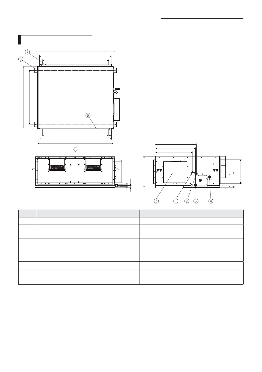
Drawing of the indoor unit
1306(51.42) Suspension position
1188(46.77) Air inlet duct ange
140X8=1120(44.09)
1040(40.94)
914 Suspension position
Unit : mm(inch)
140X8=1120(44.09)
1188(46.77) Air outlet duct ange
1240(48.82)
No. Name Description
①
②
③
④
⑤
⑥
⑦
⑧
Liquid pipe connection ø9.52(3/8")
Gas pipe connection AM076✴✴✴ : ø19.05(3/4")
Drain pipe connection VP25[OD ø32(1.26"), ID ø25(0.98")]
Drain pipe connection (Option drain pump) VP25[OD ø32(1.26"), ID ø25(0.98")]
Power supply/Communication connection
Air discharge grille ange
Air suction ange
Hook ø9.52(3/8") or M10
34
660(25.98)
647(25.47)
598(23.54)
470(18.50)
OD Ø32
35
Discharge side
AM096✴✴✴ : ø22.22(7/8")
22(0.87)
93
100X2=200
29(1.14)
Suction side
(3.66)
(7.87)
385(15.16)
209(8.23)
236(9.29)
8

Indoor Unit Installation
It is recommended to install theY-joint before installing the indoor unit.
1. Place the pattern sheet on the ceiling at the spot where you want to install
the indoor unit.
• Since the diagram is made of paper, it may shrink or stretch slightly
due to temperature or humidity. For this reason, before drilling the
NOTE
holes maintain the correct dimensions between the markings.
ENGLISH
2. Insert bolt anchors, use existing ceiling supports or construct a suitable
support as shown in gure.
3. Install the suspension bolts depending on the ceiling type.
• Ensure that the ceiling is strong enough to support the weight of
the indoor unit. Before hanging the unit, test the strength of each
CAUTION
attached suspension bolt.
• If the length of suspension bolt is more than 1.5 m(4.92 ft), it is
required to prevent vibration.
• If this is not possible, create an opening on the false ceiling in order
to be able to use it to perform the required operations on the indoor
unit.
4. Screw eight nuts to the suspension bolts making space for hanging the
indoor unit.
• You must install the suspension bolts more than four when
installing the indoor unit.
CAUTION
5. Hang the indoor unit to the suspension bolts between two nuts.
• Piping must be laid and connected inside the ceiling when
suspending the unit. If the ceiling is already constructed, lay the
NOTE
piping into position for connection to the unit before placing the
unit inside the ceiling.
6. Screw the nuts to suspend the unit.
7. Adjust level of the unit by using measurement plate for all 4 sides.
• For proper drainage of condensate, give a 1° slant to the left or right
side of the unit which will be connected with the drain hose, as
NOTE
shown in the gure. Make a tilt when you wish to install the drain
pump, too.
Concrete
Hole in anchor
Hole in plug
Suspension bolt(Φ9.52(3/8") or M10)
Ceiling support
Rubber
Insert
1°
Drain hose port
9
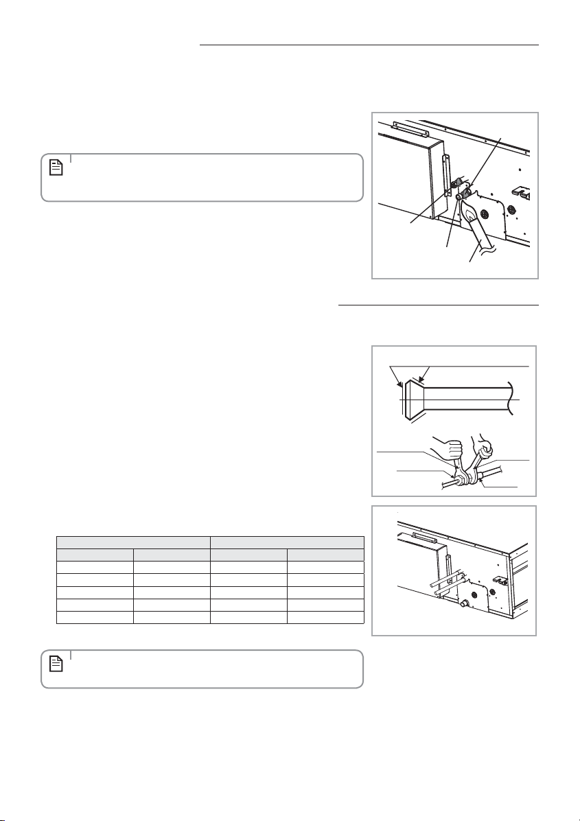
Purging the Unit
On delivery, the indoor unit is loaded with inert gas. All this gas must therefore be purged before connecting the assembly
piping. To purge the inert gas, proceed as follows.
Unscrew the pinch pipe at the end of each refrigerant pipe.
Result : All inert gas escapes from the indoor unit.
• To prevent dirt or foreign objects from getting into the pipes during
installation, do NOT remove the pinch pipe completely until you are
NOTE
ready to connect the piping.
Liquid refrigerant
port
Gas refrigerant port
Welding ame
Wet cloth
Connecting the Refrigerant Pipe
There are two refrigerant pipes of diering diameters:
f A smaller one for the liquid refrigerant
f A larger one for the gas refrigerant
f The inside of copper pipe must be clean & has no dust.
The connection procedure for the refrigerant pipes varies according to the
exit position of the pipes from the indoor unit, as seen when facing the indoor
in the “A” side.
f Liquid refrigerant port
f Gas refrigerant port
f Drain hose port
1. Remove the pinch pipe on the pipes and connect the assembly pipes to each
pipe, tightening the nuts, rst manually and then with a torque wrench, a
spanner applying the following torque.
Outer diameter Torque
mm inch N•m Ibf•ft
6.35 1/4 14 ~ 18 10.3 ~ 13.3
9.52 3/8 34 ~ 42 25.1 ~ 31.0
12.7 1/2 49 ~ 61 36.1 ~ 45.0
15.88 5/8 68 ~ 82 50.2 ~ 60.5
19.05 3/4 100 ~ 120 73.8 ~ 88.5
• Must apply refrigerant oil on the aring area to prevent a leak.
NOTE
2. Be sure that there must be no crack or kink on the bended area.
Refrigerant oil
Torque wrench
Flare nut
Spanner
Union
A
❋ The designs and shape are subject
to change according to the model.
10
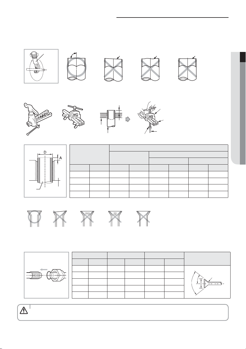
Cutting/Flaring the Pipes
1. Make sure that you prepared the required tools. (pipe cutter, reamer, aring tool and pipe holder)
2. If you want to shorten the pipe, cut it using a pipe cutter ensuring that the cut edge remains at 90° with the side of the
pipe. There are some examples of correct and incorrect cut edges below.
Pipe
cutter
Pipe
3. To prevent a gas leak, remove all burrs at the cut edge of the pipe using a reamer.
4. Carr y out aring work using aring tool as shown below.
Flaring tool
Clutch type Wing nut type
Oblique90° Rough Burr
Die
Copper pipe
A
Flare nut
Yor k
Die
Copper pipe
ENGLISH
Depth of aring part [A]
Using conventional aring tool
Clutch type Wing nut type
Pipe
Flare
Pipe diameter
[D]
mm inch mm inch mm inch mm inch
6.35 1/4 0~0.5 0~0.02 1.0~1.5 0.04~0.06 1.5~2.0 0.06~0.08
9.52 3/8 0~0.5 0~0.02 1.0~1.5 0.04~0.06 1.5~2.0 0.06~0.08
12.7 1/2 0~0.5 0~0.02 1.0~1.5 0.04~0.06 1.5~2.0 0.06~0.08
15.88 5/8 0~0.5 0~0.02 1.0~1.5 0.04~0.06 1.5~2.0 0.06~0.08
Using aring tool
for R-410A
5. Check if you ared the pipe correctly. There are some examples of incorrectly ared pipes below.
InclinedCorrect
Surface
CrackedDamaged
Uneven
Thickness
6. Align the pipes and tighten the are nuts rst manually and then with a torque wrench, applying the following torque.
Outer diameter (D) Torque (A) Flare dimension (L)
mm inch N•m lbf.ft mm inch
6.35 1/4 14~18 10.3~13.3 8.7~9.1 0.34~0.36
9.52 3/8 34~42 25.1~31.0 12.8~13.2 0.50~0.52
12.7 1/2 49~61 36.1~45.0 16.2~16.6 0.64~0.65
15.88 5/8 68~82 50.2~60.5 19.3~19.7 0.76~0.78
19.05 3/4 100~120 73.8~88.5 23.6~24.0 0.93~0.94
• In case of needing brazing, you must work with Nitrogen gas blowing.
CAUTION
Flare shape
mm(inch)
R 0.4~0.8
(0.016~0.032)
LD
45° ±2°
90° ±2°
11
Performing leak test & insulation
Leak test
LEAK TEST WITH NITROGEN (before opening valves)
In order to detect basic refrigerant leaks, before recreating the vacuum
and recirculating the R-410A, it’s responsibility of installer to pressurize the
whole system with nitrogen (using a pressure regulator) at a pressure above
4.1MPa(594.7 psig) (gauge).
LEAK TEST WITH R-410A (after opening valves)
Before opening valves, discharge all the nitrogen into the system and create
vacuum. After opening valves check leaks using a leak detector for refrigerant
R-410A.
• Discharge all the nitrogen to create a vacuum and charge the system.
CAUTION
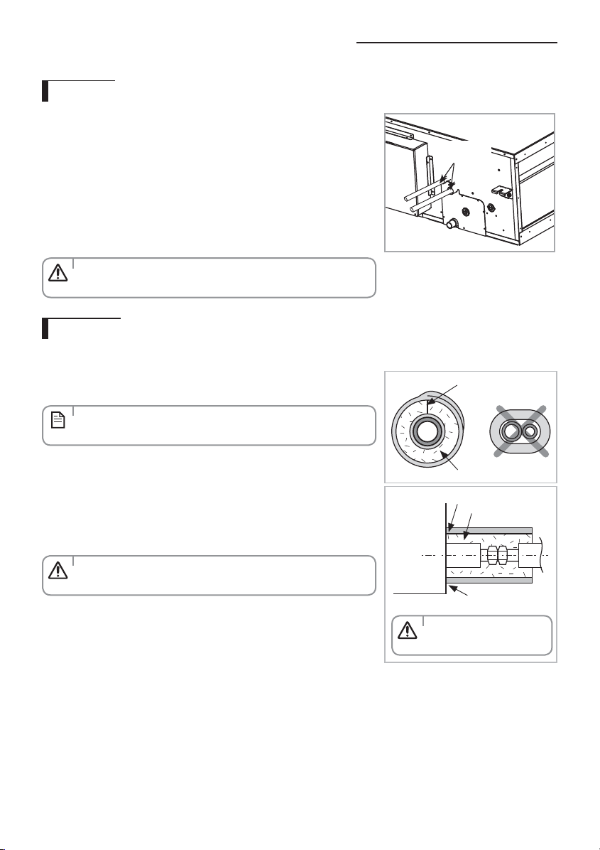
Insulation
Once you have checked that there are no leaks in the system, you can insulate the piping and hose.
Leak check
1. To avoid condensation problems, place T13.0 (1/2") or thicker Acrylonitrile
Butadien Rubber separately around each refrigerant pipe.
• Always make the seam of pipes face upwards.
NOTE
2. Wind insulating tape around the pipes and drain hose avoiding to compress
the insulation too much.
3. Finish wrapping insulating tape around the rest of the pipes leading to the
outdoor unit.
4. The pipes and electrical cables connecting the indoor unit with the outdoor
unit must be xed to the wall with suitable ducts.
• All refrigerant connection must be accessible, in order to permit
either unit maintenance or removing it completely.
CAUTION
Insulation cover pipe
Indoor unit
• Must t tightly against
body without any gap.
CAUTION
No gap
NBR
(T13.0 (1/2") or thicker)
Insulation pipe
Be sure to overlap the
insulation
12
 Loading...