

Samsung SH09ZW8X, SH12ZWHDX, UQ09W8WE, UQ12WHWED, UQ12WHWE Service Manual
...
ROOM AIR CONDITIONER
AQ09W8WE UQ09W8WE
SH12ZWHD SH12ZWHDX
SH09ZW8X
INDOOR UNIT
AQ12WHWE
AQ12WHWED UQ12WHWED
SH09ZW8
SERVICE
OUTDOOR UNIT
UQ12WHWE
Manual
CONTENTSAIR CONDITIONER
1. Product Specifications
2. Disassembly and Reassembly
3. Refrigerating Cycle Diagram
4. Set Up the Model Option
5. Troubleshooting
6. Exploded Views and Parts List
7. Block Diagram
8. Wiring Diagram
9. Schematic Diagram
1. Product Specifications
1-1 Table
Item
Type
Cooling -
g -
Heati
n
Dehumidify
Air Volume
Performance
Noise
Energ
Powe
Powe
Operating Current
Power
Powe
Startin
Powe
Oute
Weight(Net) kg
Refrigeran
Drai
Size
Compress
Oi
Blow
Hea
t Exchanger
Refrigeran
Freeze
r Oil Capacity cc
Refrigeran
Protectio
n Device(OLP)
Coolin
g Test Condition
Maximu
m Operation Condition
ing l/h
Cooli
Heating
Cooli
Heati
y Efficiency Ratio
V-Hz
r
Consumption
r
r Factor
g Current A
r Cord Number of Core Wire
r Dimension
t Pipe
n Hose D x L(mm)
Type
o
r Motor Type
l Type
Type
er Motor Type
t Control Unit
t to Change(R410A) g
Cooling
Heati
Cooli
Heating
Cooli
Heati
Cooli
Heating
Leng
Capaci
h x Height
Widt
x Depth
Liquid mm x L(m)
GAS mm x L(m)
d Output
Rate
d Output W
Rate
Model
g
n
ng
ng
ng
n
g
n
g
ng
ng
th m
ty A
m3/min
dB
mm
inch
AQ12WHWE[D]/SH12ZWHD(X) AQ09W8WE/SH09ZW8(X)
Indoor
Indoor unit Outdoor unit
Wall-mounted
12000 BTU/h 2600
13000 BTU/h 2900
1.2 0
8.3 - 7.5 -
8.3 - 8.0 -
41 / 39
/ 37 53 / 53 38 / 36 / 34 51 / 51
41 / 39 / 37 53 / 53 38 / 36 / 34 51 / 51
-
W
A
%
825 x 285 x 189 720 x 548 x 265 825 x 285 x 189 660 x 475 x 242
32.5 x 11.2 x 7.44 28.4 x 21.6x 10.4 32.5 x 11.2 x 7.44 26.0 x 18.7 x 9.53
Cross-fl
2RO
INDOOR UNIT : DB27˚C WB19˚C OUTDOOR UNIT : DB35˚C WB24˚C
INDOOR
10 BTU/h 2.68 W
11.02 BTU/h 3.22 W
/ 240-50 1-220 / 240-50
1-22
0
1200 9
1180 900
5.3 4
5.2 4
94.34
94.55 97
-
2 2
3 3
0V-10A 250V-10A
25
8.1 33.2 7.8 26.0
ø12.7 x 5.0 9.52 x 5.0
ø6.35x 5.0 6.35 x 5.0
ø1
8 x 550 18 x 550
48D129JUAEL 44B102JXA
- -
1206 10
SUNISO-467SD/NOC
ow Propeller
ste
el steel
15 50
W 14STEP 1ROW 20STEP 2ROW 10STEP 1ROW 18STEP
CAPIL
LARY TUBE CAPILLARY TUBE
600 3
870 650
RBC12074-12500 RBC121
UNIT : DB32˚C WB23˚C OUTDOOR UNIT : DB43˚C WB26˚C
unit Outdoor unit
Wall-mounted
W
W
9
.
/W
/W
70
3
.
.0
98
.8
-
ø
ø
ø
L
E
05
SUNISO-467SD/NOC
Cross-flow Propeller
ste
el steel
15 50
60
88-12500
1Samsung Electronics
2. Disassembly and Reassembly
Stop operation of the air conditioner and remove the power cord before repairing the unit.
2-1 Indoor Unit
No Parts Procedure Remark
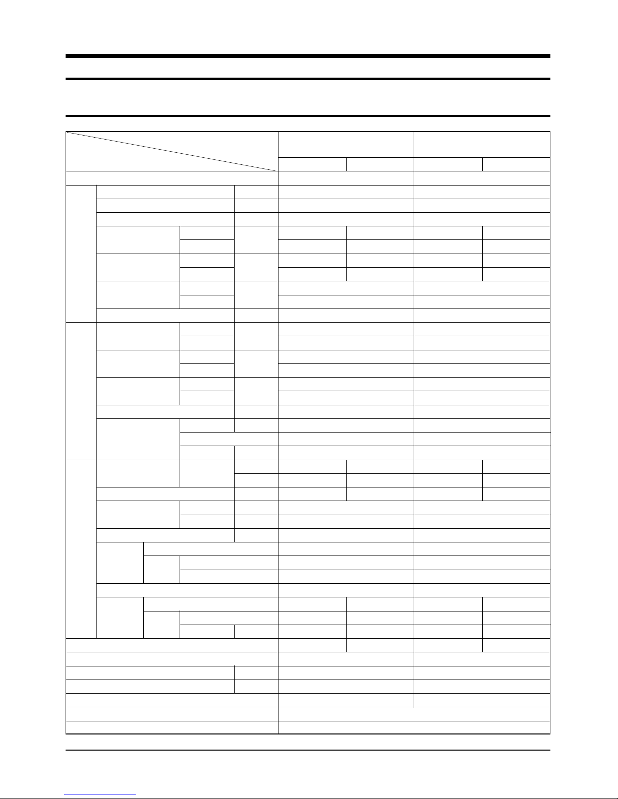
1 Front Grille
1) Stop the air conditioner operation and
block the main power.
2) Open the Front Grille by pulling right and
left sides of the hook.
3) Loosen 1 of the right screw and detach
the Terminal Cover.
4) Detach the thermistor from the Front
Grille.
5) Loosen 2 fixing screws of Front Grille.
Samsung Electronics2
Disassembly and Reassembly
No Parts Procedure Remark
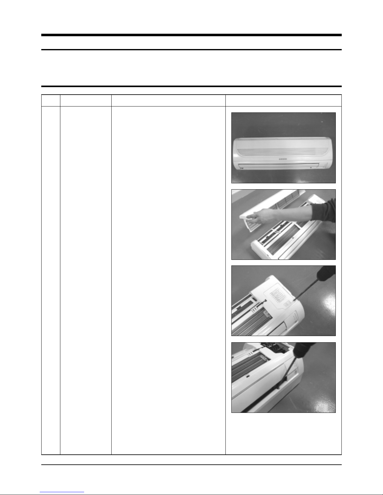
6) Unlock 2 hooks to fix Panel Front and
Tray Drain.
7) Unlock 3 hooks to fix Panel Front and
Back-Body.
2
Control-In
(Main PCB)
1) Take all the connector of PCB upper side
out. (Inclusion Power Cord)
2) Detach the outdoor unit connection wire
from the Terminal Block.
3) Loosen 4 fixing screws of Ass'y Control-In.
3
Tray Drain
1) Pull Tray Drain out from the Back Body.
3Samsung Electronics
Disassembly and Reassembly
No Parts Procedure Remark
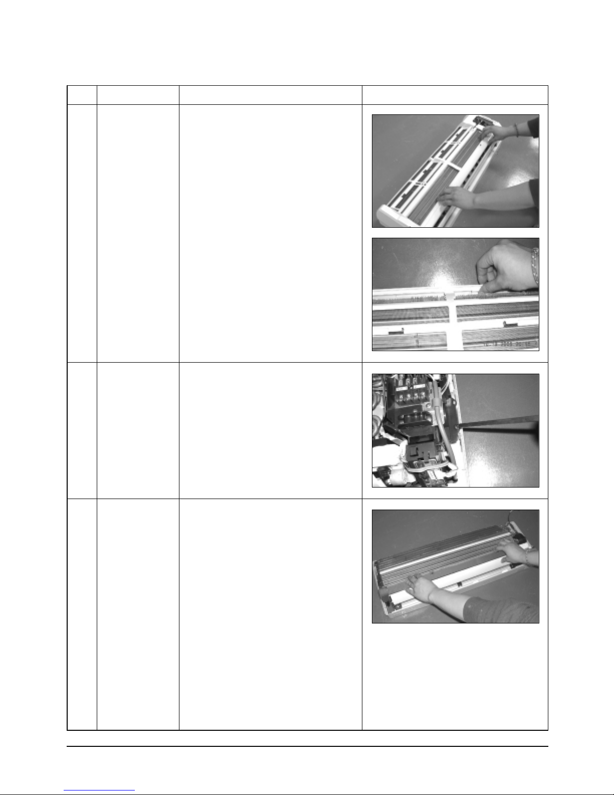
4
Heat Exchanger
1) Loosen 2 fixing earth screws of right side.
2) Detach the Connection Pipe.
3) Detach the Holder Pipe at the rear side.
4) Loosen the 3 fixing screws of right and left
side.
5) Lifting the Heat Exchanger up a little to
push the up side for separation from the
indoor unit.
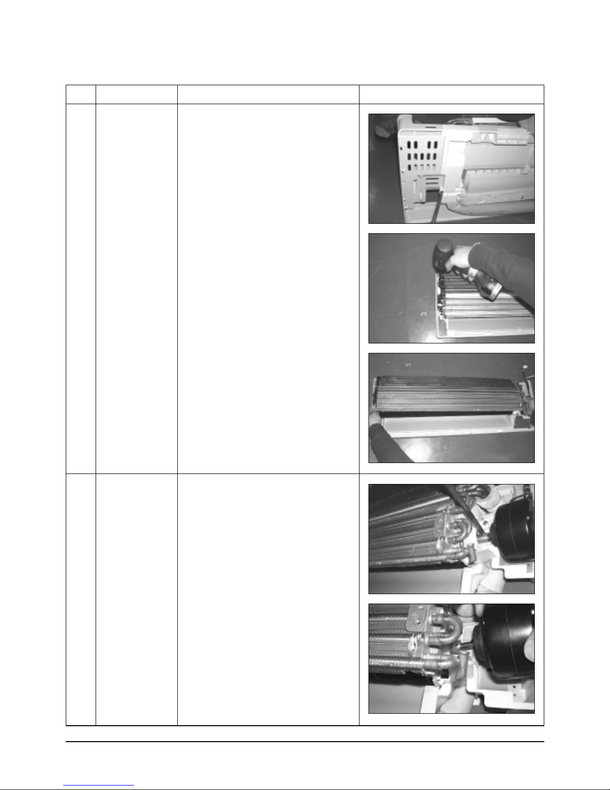
5
Fan Motor
&
Cross Fan
1) Loosen the fixing screw and detach the
Motor Holder.
2) Detach the Fan Motor from the Fan.
3) Detach the Fan From the left Holder
Bearing.
Samsung Electronics4
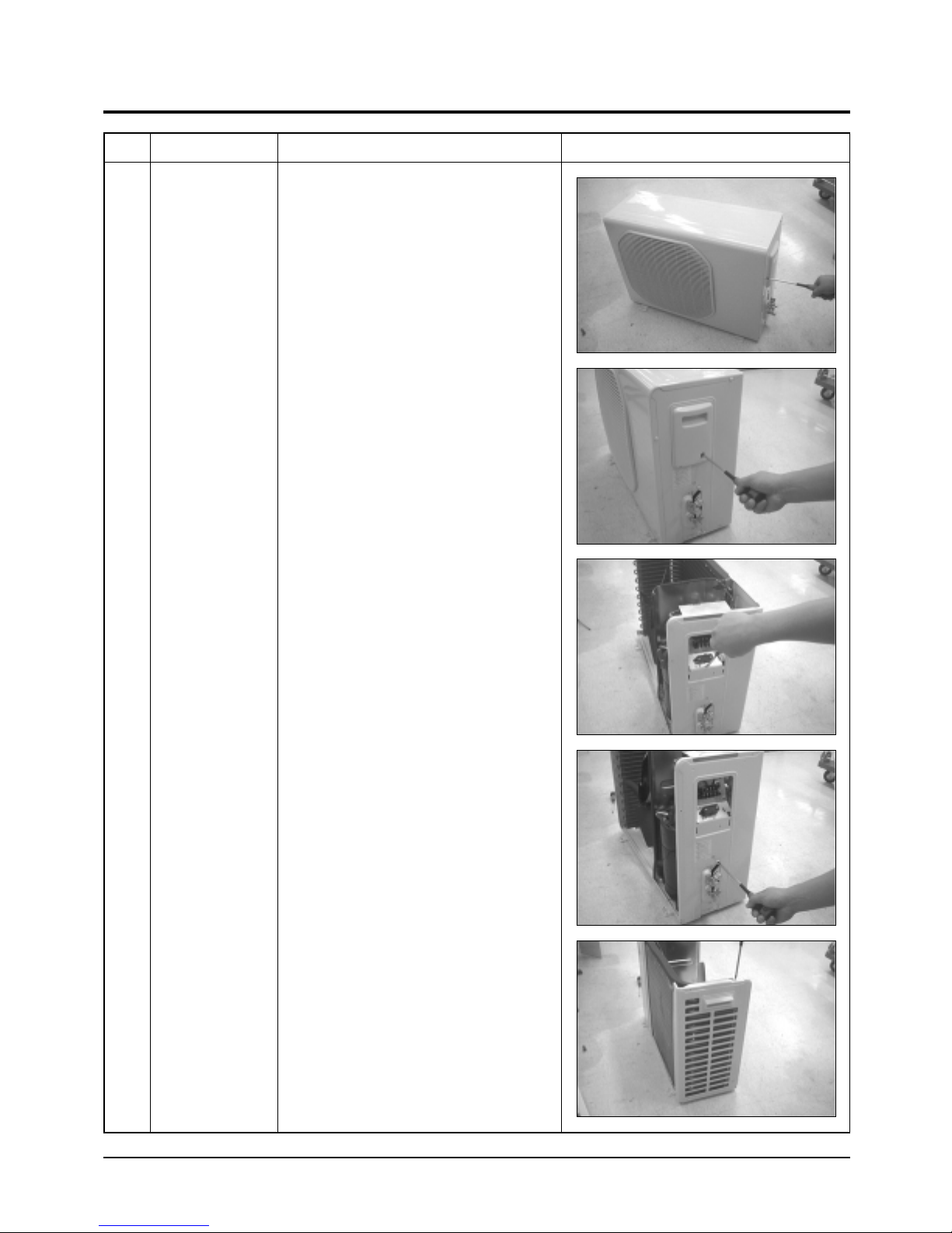
2-2 Outdoor Unit
No Parts Procedure Remark
1 Common Work
1) Loosen each 3 fixing screws on both right
and left Cabinet-Side edge and a fixing
screw on the Cabinet-Front lower to detach
the Cabinet-Front.
2) Loosen 2 fixing screws of the
Ass'y-Control.
3) Loosen 6 fixing screws of the Cabinet-Side
RH.
4) Loosen 2 fixing screws of the Cabinet-Side
LF.
5Samsung Electronics
Disassembly and Reassembly
No Parts Procedure Remark
5) Loosen 1 fixing Cable-Tie of the Cabinet-Side
LF.
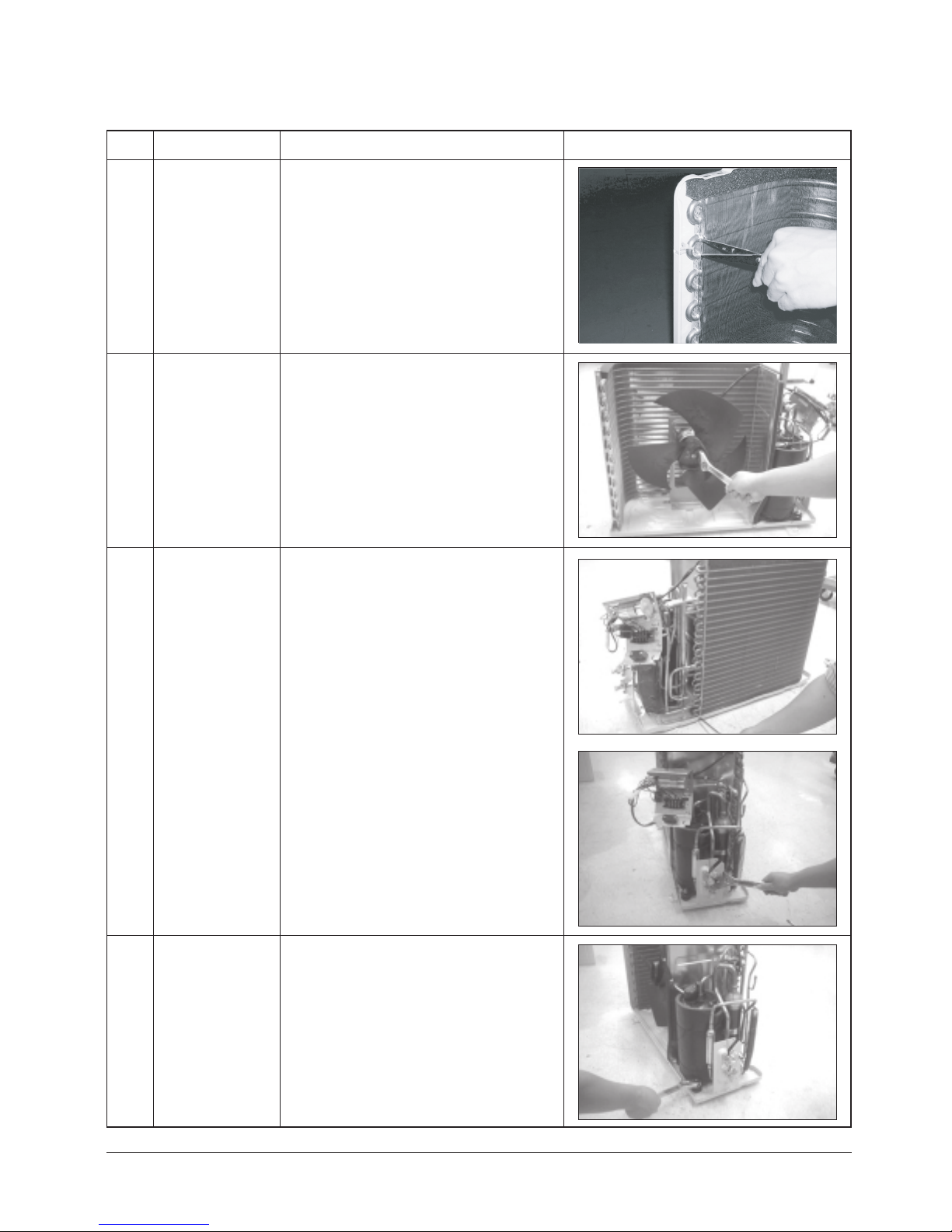
2
Fan
& Motor
1) Detach the Nut Flange.(Turn counterclockwise
because the screw is right-handed)
Detach the Fan.
2)
3) Loosen 4 fixing screws to detach
Motor.
the
Exchanger
Heat
3
1) Loosen 2 fixing screws on both sides.
2) Disassemble the pipe in both inlet and
with welding torch.
outlet
3) Detach the Heat Exchanger.
4
Compressor
1) Loosen the Terminal Cover nut to open the
Terminal
2) Disassemble the cloth sound felt.
3) Disassemble the pipe in both inlet and
outlet
torch.
4)
Disassemble the pipe in both inlet and
outlet
5)
Loosen the 3 bolts at the bottom.
6)
Detach the Compressor.
Cover.
of the Compressor with welding
of the Condenser with welding torch.
Samsung Electronics6
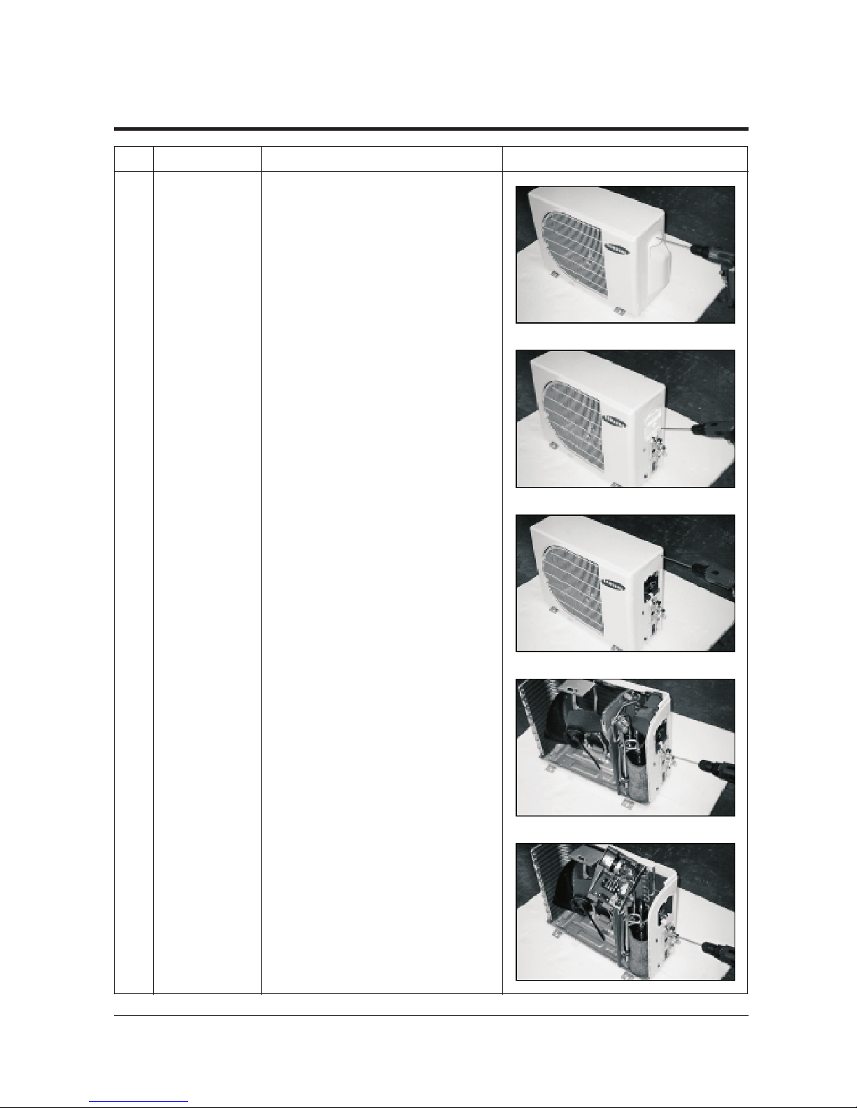
No Parts Procedure Remark
1Common Work
1)
Loosen 2 fixing screws on the Cover
Valve and
take off the Cover Valve.
2)
Loosen 1 fixing screws of the Cover Control
and take off the Cover Control.
3) Loosen 8 fixing screws of the Cabi-Front
and take off the Cabi-Front.
4)
Loosen the fixing screws of the Assy Control
Out.
5) Loosen the fixing screws of the Assy
Cabi-side and take off the Cabi-side.
2-3 Outdoor Unit
7Samsung Electronics
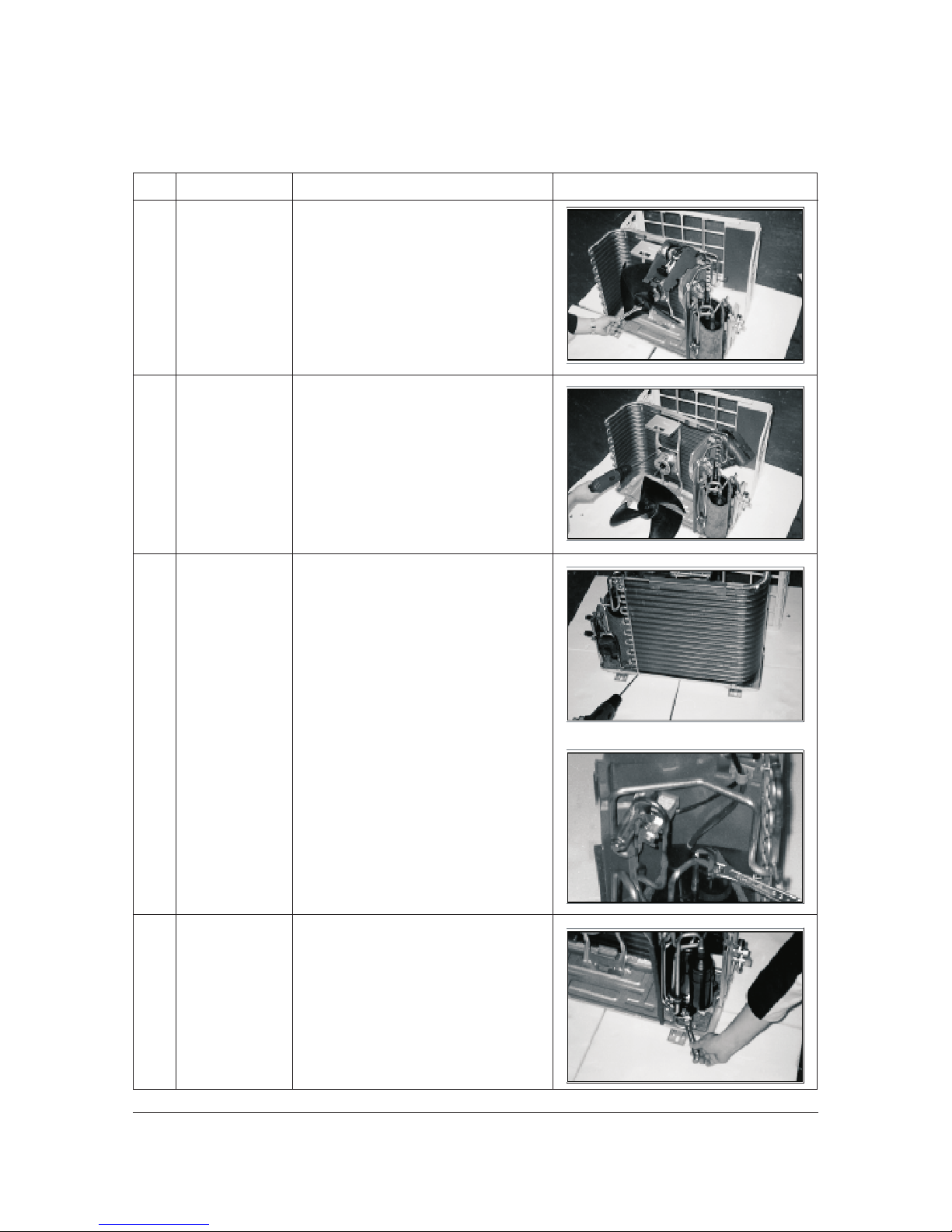
Disassembly and Reassembly
No Parts Procedure Remark
2
3
4
Fan
&
Motor
Heat
Exchanger
Compressor
1) Detach the Nut Flange.(Turn counterclockwise
because the screw is right-handed)
2) Detach the Fan.
1 ) Loosen 4 fixing screws to detach
the
Motor.
1) Loosen 2 fixing screws on both sides.
2) Disassemble the pipe in both inlet and
outlet
with welding torch.
3) Detach the Heat Exchanger.
1) Loosen the Terminal Cover nut to open the
Terminal
Cover.
2) Disassemble the cloth sound felt.
3) Disassemble the pipe in both inlet and
outlet
of the Compressor with welding
torch.
4)
Disassemble the pipe in both inlet and
outlet
of the Condenser with welding torch.
1)
Loosen the 3 bolts at the bottom.
2)
Detach the Compressor.
2 ) Loosen 2 fixing screws to detach
the the Bracket of Motor.
.
Samsung Electronics8
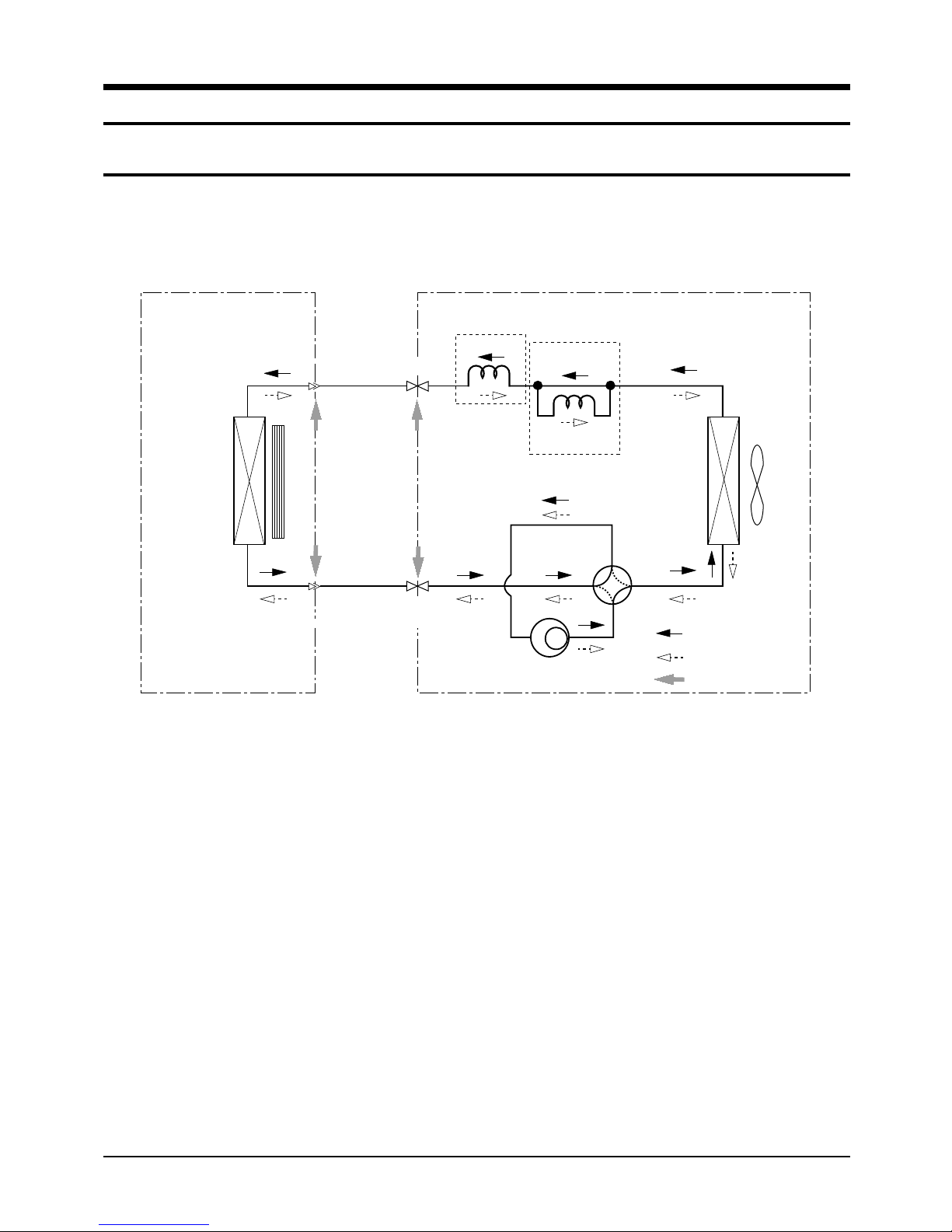
Cooling
Heating
Gas Leak Check Polnt
3. Refrigerating Cycle Diagram
3-1 Refrigerating Cycle Diagram
Indoor Unit
Heat
Exchanger
(Evaporator)
Outdoor Unit
T
1
Liquid side
Cross fan
T
2
Gas side
2-Way valve
3-Way valve
Capillary tube
✳Note
Check valve
Capillary tube
Heat
Exchanger
(Evaporator)
Propeller fan
4-Way valve
Compressor
9Samsung Electronics
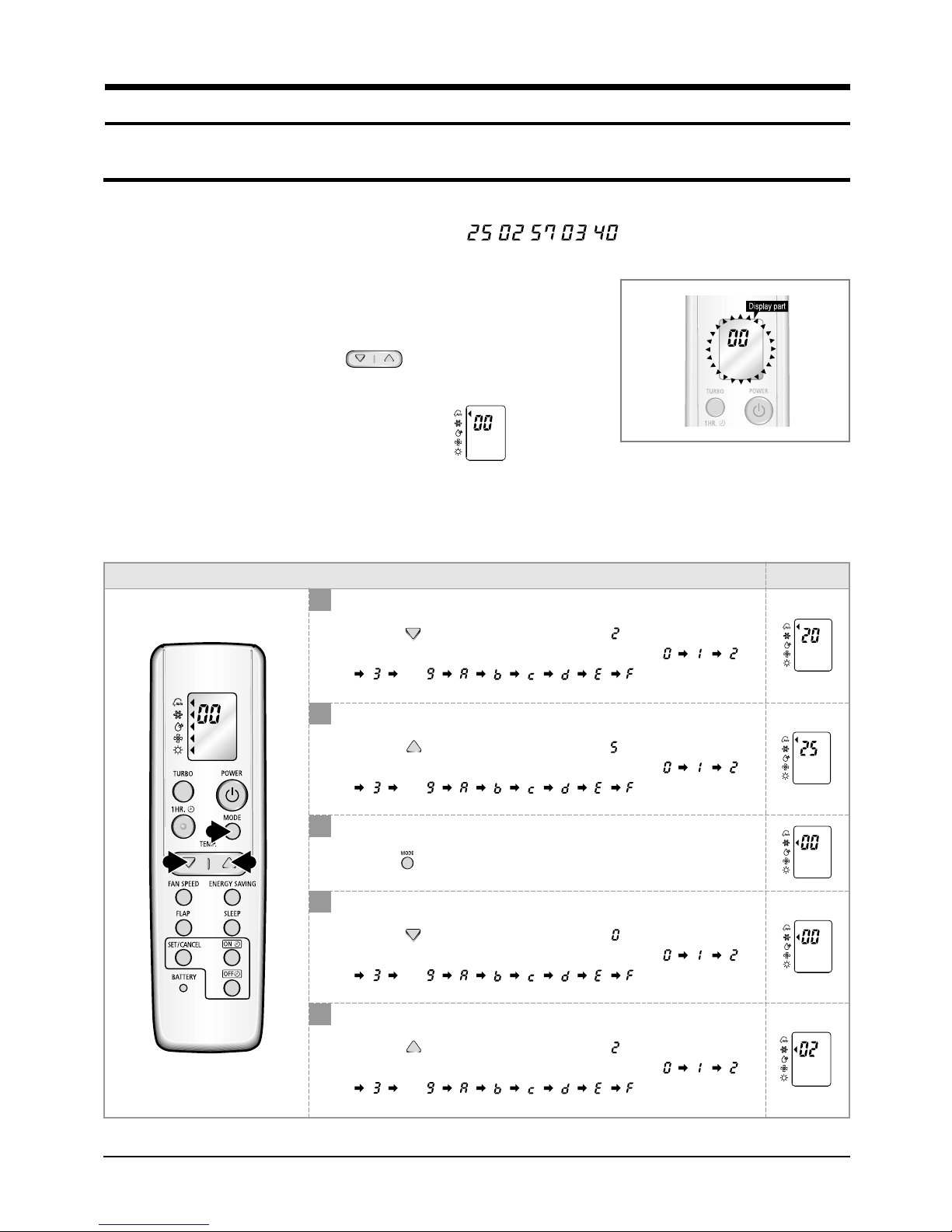
4. Set Up the Model Option
4-1 Setting Option Setup Method
ex) Option No. :
Step 1 : Enter the Option Setup mode.
st
1
nd
2
Take out the batteries of remote control.
Press the temperature button simultaneously and
insert the battery again.
rd
3
Make sure the remocon display shown as .
Step 2 : Enter the Option Setup mode and select your option according to the following procedure.
Feature Display
1
Setting Option SEG1.
Push the button to set the display panel to .
Every time you push the button, the display panel reads
3
1,4 2,5
. . .
2
Setting Option SEG2.
Push the button to set the display panel to .
Every time you push the button, the display panel reads
. . .
3
Change it into the set display of Option SEG3 and SEG4
with the button.
repeatedly.
repeatedly.
4
5
Setting Option SEG3.
Push the button to set the display panel to .
Every time you push the button, the display panel reads
. . .
Setting Option SEG4.
Push the button to set the display panel to .
Every time you push the button, the display panel reads
. . .
repeatedly.
repeatedly.
Samsung Electronics10
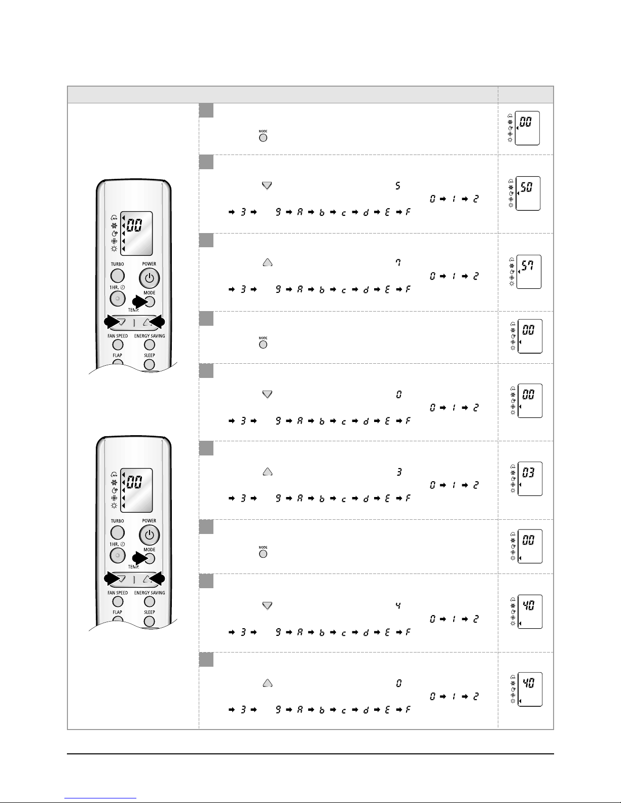
Feature Display
6,9
7,10 8,11
12
13 14
6
Change it into the set display of Option SEG5 and SEG6
with the button.
7
Setting Option SEG5.
Push the button to set the display panel to .
Every time you push the button, the display panel reads
. . .
8
Setting Option SEG6.
Push the button to set the display panel to .
Every time you push the button, the display panel reads
. . .
9
Change it into the set display of Option SEG7 and SEG8
with the button.
Set Up the Model Option
repeatedly.
repeatedly.
10
Setting Option SEG7.
Push the button to set the display panel to .
Every time you push the button, the display panel reads
. . .
11
Setting Option SEG8.
Push the button to set the display panel to .
Every time you push the button, the display panel reads
. . .
12
Change it into the set display of Option SEG9 and SEG10
with the button.
13
Setting Option SEG9.
Push the button to set the display panel to .
Every time you push the button, the display panel reads
. . .
14
Setting Option SEG10.
Push the button to set the display panel to .
Every time you push the button, the display panel reads
. . .
repeatedly.
repeatedly.
repeatedly.
repeatedly.
11Samsung Electronics
 Loading...