

Samsung APH180HD, APH180CD, APH180ED Service Manual
SERVICE
Manual
APH180HD/ED/CD
CONTENTSAIR CONDITIONER
1 . P re c a u t i o n s
2 . P roduct Specifications
3 . Operating Instru c t i o n s
4 . Disassembly and Reassembly
5 . Tro u b l e s h o o t i n g
6 . Exploded Views and Parts List
7 . Block Diagrams
8 . PCB Diagrams
9 . Wiring Diagrams
1 0 . Schematic Diagrams
PACKAGED AIR CONDITIONER
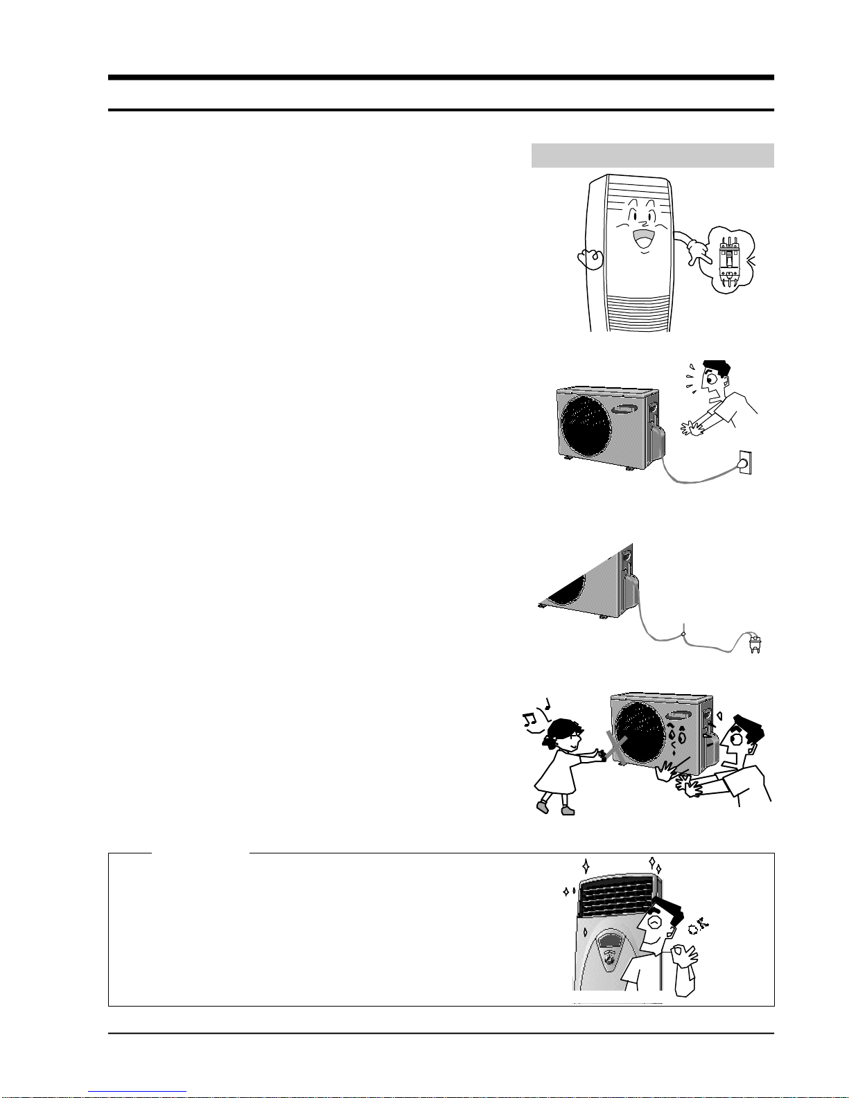
1) Turn off the the power.
Be sure to turn off the power before attempting to repair the
unit such as the disassembly of the unit.
2) Be careful of electric shock
When checking the circuit with the power connected in
unavoidable circumstances, take special care not to touch the
live parts. There is a danger of electric shock.
3) Use of appropriate parts
Be sure to use the genuine parts of the relevant model when
it is necessary to replace parts. (Replace parts instead of
repairing with regard to the malfunctioning of electric contact
areas. Never attempt to modify the unit. It is extremely dangerous for the consumer to attempt to repair the unit on
his(her) own.)
4) Use of proper tools
Use appropriate tools for repair, and use measuring equipment after accurate calibration. Using worn tools may result
in problems, including poor contact and poor connection.
5) Avoid damage to electric wire or electric cord.
Check the electric cord or electric wire for any damage during
repair.
Be sure to replace it if damaged.
6) Avoid intermediate connection of the electric cord.
Never attempt to make an intermediate connection by cutting
the middle area of the electric cord or make a connection to
the power receptacle as it is very dangerous, causing problems or fire.
7) Checking of insulation
Be sure to check the insulation resistance after completion of
the assembly work.
(Check whether the insulation resistance of the electric wire
and grounding terminal is over 30MΩ by using the insulation
resistance tester, and then connect the power source.)
8) Checking of grounding
Check the grounding condition, and perform repair if poorly
grounded.
9) Checking of installation condition
Check the installation condition of the unit, and perform
repair if there is any defective area.
If the unit remains in an unstable installing condition, install
it at a new site.
10) Be careful of children
As the repair of the unit involves a lot of dangerous elements,
do not allow children to approach nearby during repair work.
Samsung Electronics
1-1
1. Precautions
Turn off the sub power switch separately installed.
No connection with the power receptacle
Upon completion of the repair, clean the air
conditioner and surrounding area, and
inform the customer of completion of the repair.
Cleaning
Samsung Electronics
2-1
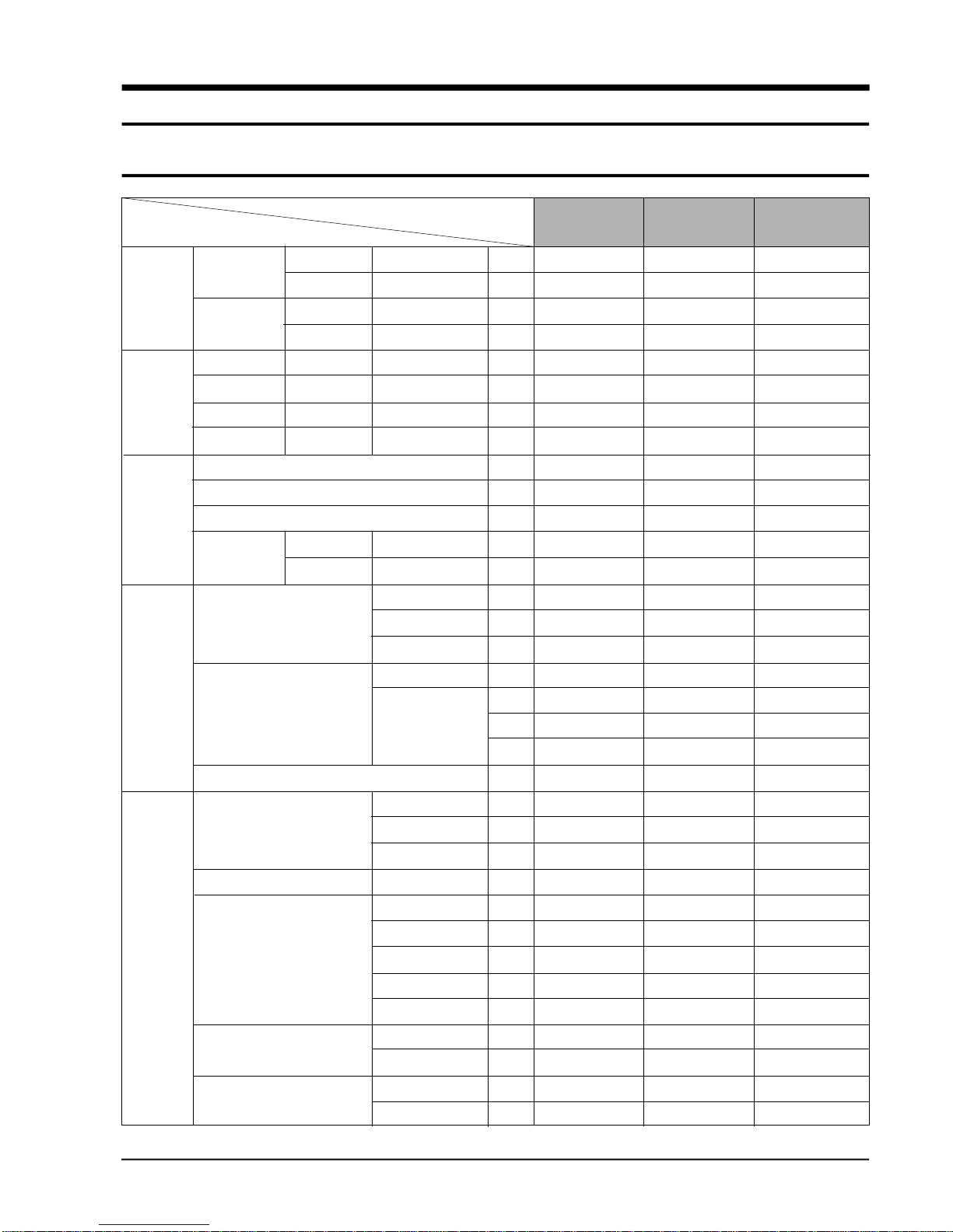
2. Product Specifications
2-1 Table
Model
Item
Unit Width x Height x Depth mm
Packed Width x Height x Depth mm
Unit Width x Height x Depth mm
Packed Width x Height x Depth mm
Unit kg
Packed kg
Unit kg
Packed kg
1. Capacity(Cooling /Heating) W
2. Power consumption(Cooling/Heating) W
3. Current consuption(Cooling/Heating) A
4. Noise Indoor unit High dBA
(Cooling/Heating) Outdoor unit dBA
1. Evaporator Construction Row x Step
Fin
Capillary tube
2. Blower motor Capacitor
RPM HIgh
Medium
Low
3. Fuse V/A
1. Condenser Construction Row x Step
Fin
Capillary tube
2. Refrigerant volume R22 g
3. Compressor Maker
Model
Type
Capacitor
Crankcase heater W
4. Fan motor Capacitor
RPM
5. Service v/v High pressure side inch
Low pressure side inch
APH180HD APH180ED APH180CD
500 x 1700 x 330 500 x 1700 x 330 500 x 1700 x 330
590 x 1785 x 465 590 x 1785 x 465 590 x 1785 x 465
765 x 532 x 280 765 x 532 x 280 765 x 532 x 280
884 x 593 x 380 884 x 593 x 380 884 x 593 x 380
35 38 35
41 44 41
40 40 38
46 46 44
4700/5600 4700/6400 4700
1900/1900 1900/2700 1900
9.5/9.5 9.5/14 9.5
45 45 45
55 55 55
2x24 2x24 2x24
WAVE 1.4 WAVE 1.4 WAVE 1.4
ø1.3x3 ø1.3x3 ø1.3x3
450V/4.0uF 450V/4.0uF 450V/4.5uF
500 500 530
450 450 480
400 400 430
250V 3.15A 250V 3.15A 250V 3.15A
2x20 2x20 2x20
D5 1.7 D5 1.7 D5 1.7
Ø2.0x1 Ø2.0x1 Ø2.0x1
1,450 1,450 1,200
SAMSUNG SAMSUNG SAMSUNG
48B 180MV 1E7 48B 180MV 1E7 48B 180MV 1E7
ROTARY ROTARY ROTARY
420V/45uF 420V/45uF 420V/45uF
40 40 -
450V/2.5uF 450V/2.5uF 450V/2.5uF
1050 1050 1050
3/8 3/8 1/4
1/2 1/2 1/2
Size
Weight
Indoor unit
Outdoor unit
Outdoor unit
Indoor unit
Electric
characteristics
Indoor unit
Outdoor unit
2-2
Samsung Electronics
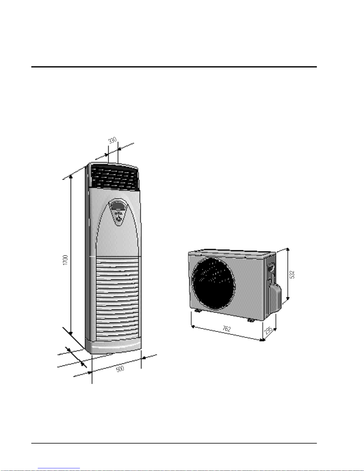
2-2 Dimensions
Indoor Unit
Outdoor Unit
unit : mm
330
Samsung Electronics
3-1
3. Operating Instructions
3-1 Control System Chart
Operation Mode
Operation selector mode
Fan speed selector mode
A i rflow selector mode
R e s e rvation operation
m o d e
Convenience function
Main switch operation
Remote control operation
Auto
Cooling operation
Dry operation
Heating operstion
Manual 3-step
Natural
Auto
Left/Right turn
UP/Down Turn
Start time
reservation
Stop time
reservation
Brief reservation
Operation/stop, operation selection, blow volme selection, turbo, temperature
control
Start/stop, operation selection, fan speed selection, turbo, temperature control, reservation operation, sleeping operation, left/light turning, up/down
turning, turbo/remote
Indoor temperature control according to the set temperature.
Indoor temperature control accoding to the set temperature(18°C<->30°C)
Decide the dry cydle by the difference in room temperature(18
°C-30°C)
Indoor temperature control according to the set temperature(16
°C<->30°C)
APH180HD/180ED=(0), APH180CD=(X)
High, Medium, Low(slectable at the cool and fan mode)
The hige, midium, low wind is automaticallly changed by CHAOS calculation.
In automatically operating, it is fixed with natural wind.
The automatic fan control according to the difference between the indoor and
the set temperatures.
Selectable only by the remote control and turn and turn/stop are possible only.
Selectable only by the remote control and turn and turn/stop are possible only.
Selectable only by the remote control and the time of operation ON is set..
Selectable only by the remote control and the time of operation OFF is set..
Selectable only by eremote control and the off reservation function is performed
after 30 minutes, 1,2,3 and 5 hours.
Cooling and heating control according to the set temperature
Room temperture≥21°C±2°C(remocon input)=cooling operation
Desired temperature=24°C±2°C
Room temperature<21°C±2°C(remocon input)=heating operation
Desired temperature=22°C±2°C
Fan operstion Operation of the indoor fan moter only(High, midium, low)
Operating Instructions
3-2
Samsung Electronics
Convenience
function
Long operation
Sleeping operation
The set temperature is set to the standard-1
°C and the fan speed is set to
turbo wind, and up and down rotating blades are positioned upward.
During the initial 1hour of the sleeping selection, when the indoor temperature reaches the set temperature +1
°C, the compressor is on and off at theset
temperature.
It is on at the set temperature +2°C between 1hour and 2hours and off at the set
temperature +1°C.
After 2 hours, it is on at the temperature +3°C and off at the set temperation +2°C.
When 6hours pass after selection of sleeping operation, it stops.
Self diagnosis
function
“E 1” Displayed at the indoor temperature sensor operates abnormally.
“E 2” Displayed at the auto shutter operates abnormally.
“E 5” Displayed at the indoor evaporator temperature sensor operates abnormally.
“E 6” Displayed at the outdoor condensor temperature sensor operates abnormally.
“E 7” Displayed at the electric heater temperature sensor operates abnormally.
“ E C ” Displayed at the electric heater is overheated.
3-3
Samsung Electronics
3-2 Key Types and Functions
KEY
Operation and stop of operation
- Start durning turn on once, and stop durning turn on again
- Continous operation is impossible
Change of the operation mode
-Each one every turn on,
"AUTO" → "COOL" → "DRY" → "FAN" → "HEAT"is selected sequentially.
(standard = auto)
- continued operation is impossible.
The indoor fan motor speed is set.
-Cooling operation
Each one every turn on,
"LOW" → "MEDIUM" → "HIGH" → "AUTO" is selected sequentially. (standard = auto)
- In fan operation
"LOW" → "MEDIUM" → "HIGH" is selected sequentially. (standard = Low)
- In auto and dry operation, the fan speed is selscted with "Auto" or "Natural" so that the
key input is ignored.
- Continuous operation is impossible.
The set temperature is increased.
-Temperature:the set temperature is increased 1˚C each one every turn on.
Cooling operation:18˚C → 30˚C
Heating operation:16˚C → 30˚C
-The key operate only when the heat, cool, dry operation.
-One time and continuous operation is possible.
The set temperature is drcreased.
-Temperature:the set temperature is decreased 1˚C each one every turn on.
Cooling operation: 30˚C →18˚C
Heating operation:30˚C → 16˚C
-The key operate only when the heat, cool, dry operation.
-One time and continuous operation is possible.
Turbo function is on and off.
-Selectable all over operation mode.
-Continuous operation is impossible.
Temperature
setting
(decreasing)
Turbo
KEY NAME
Operation/
stop
Operation
selection
Fan speed
Temperature
setting
(increasing)
TACT
H e a t = A P H 1 8 0 C D ( X )
TACT
TACT
TACT
H e a t = A P H 1 8 0 C D ( X )
TACT
TACT
H e a t = A P H 1 8 0 C D ( X )
Kinds of Key
3-4
Samsung Electronics
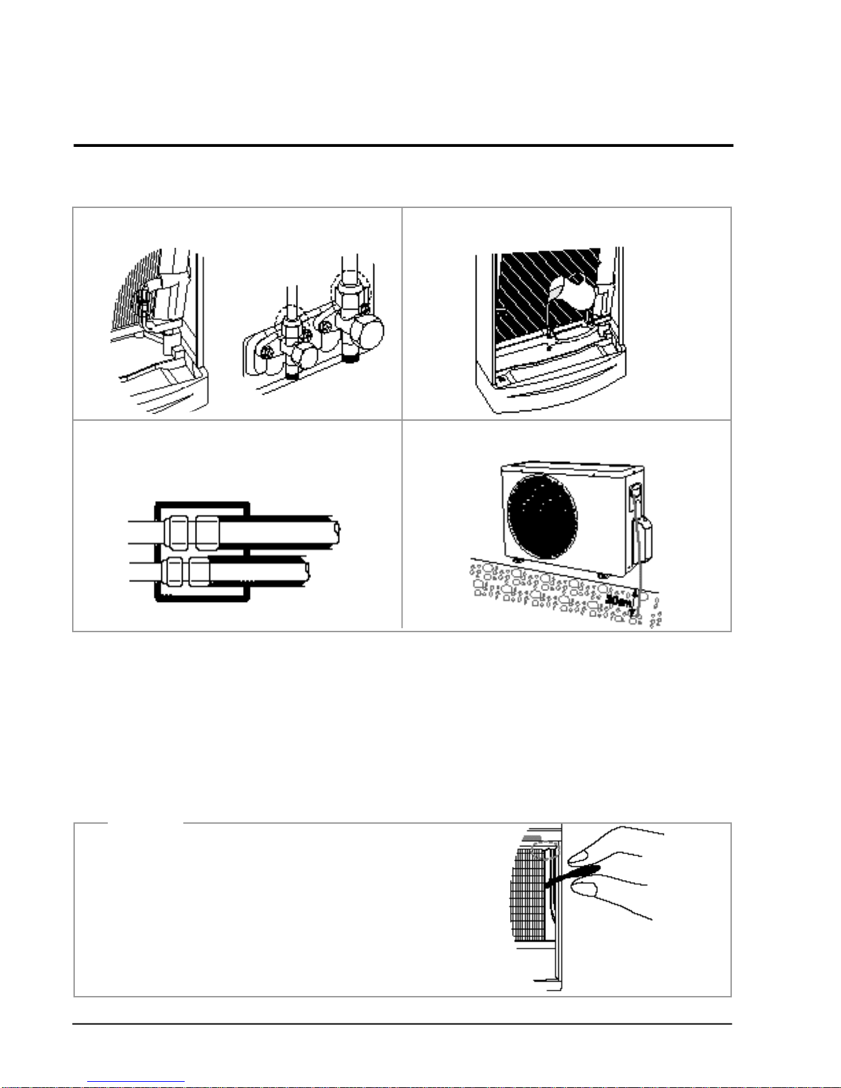
3-3 Check and Test Operation
•
Be sure to check the following again after completion of installation.
•
After checking, read the owner's instructions care f u l l y, and perform a test operation.
Then deliver the unit to the customer.
(When delivering the unit, be sure to read carefully and follow the contents of the owner's
i n s t ru c t i o n s . )
3-2-4(b) Test Operation
1. Be sure to check whether the service valve is opened before attempting to
perform the test operation.
2. Never attempt to start test operation by force pressing the electronic contactor
as it is very dangerous.
(This is very dangerous as the protective device does not work.)
3. Be sure to perform the test operation after installment.
It is easy to start the test operation in winter if you increase the sensor
temperature to 23°C ~25°C by holding the indoor temperature sensor (Cooling
operation)
Caution
Outdoor connection area
Indoor connection area
1. Check the piping connection area for any gas leakage.
3. Is the insulation of the piping in good condition? 4. Is grounding properly made?
(In case of disconnecting ground on electric panel board.)
Insulation
2. Is the drain hose properly connected?
Temperature
Sensor
Samsung Electronics
4-1
4. Disassembly and Reassembly
4-1 Indoor Unit
Stop operation of the air conditioner and remove the power before repairing the unit.
No Parts Procedure Remark
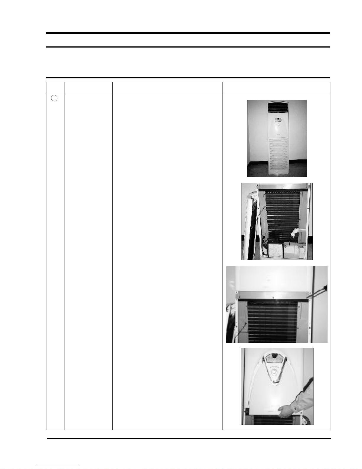
1 Front Grille
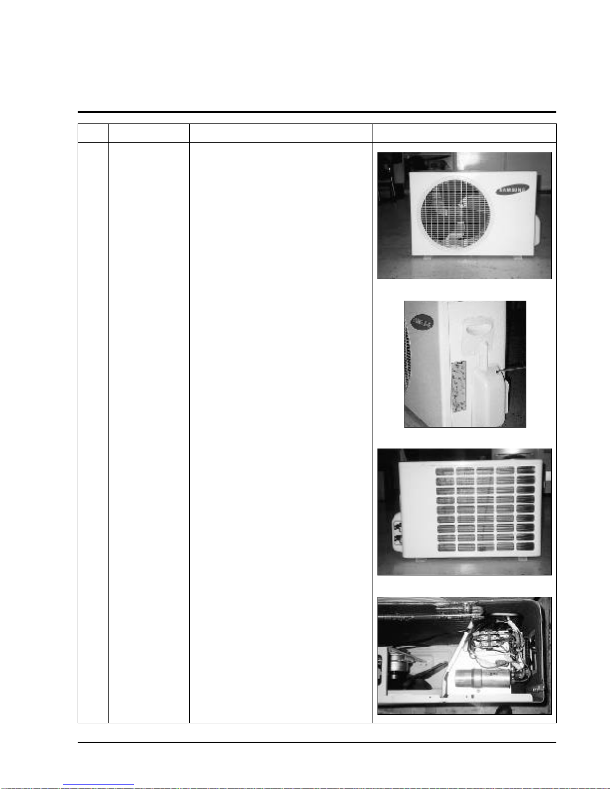
1) Packaged air conditioner indoor unit.
2) Open the inlet grille, and remove the
connector ring.
3) Loosen nine screws to remove the cover
connect and cover evap’L.
4) Loosen one screws and pull the
downward.
Disassembly and Reassembly
4-2
Samsung Electronics
No Parts Procedure Remark
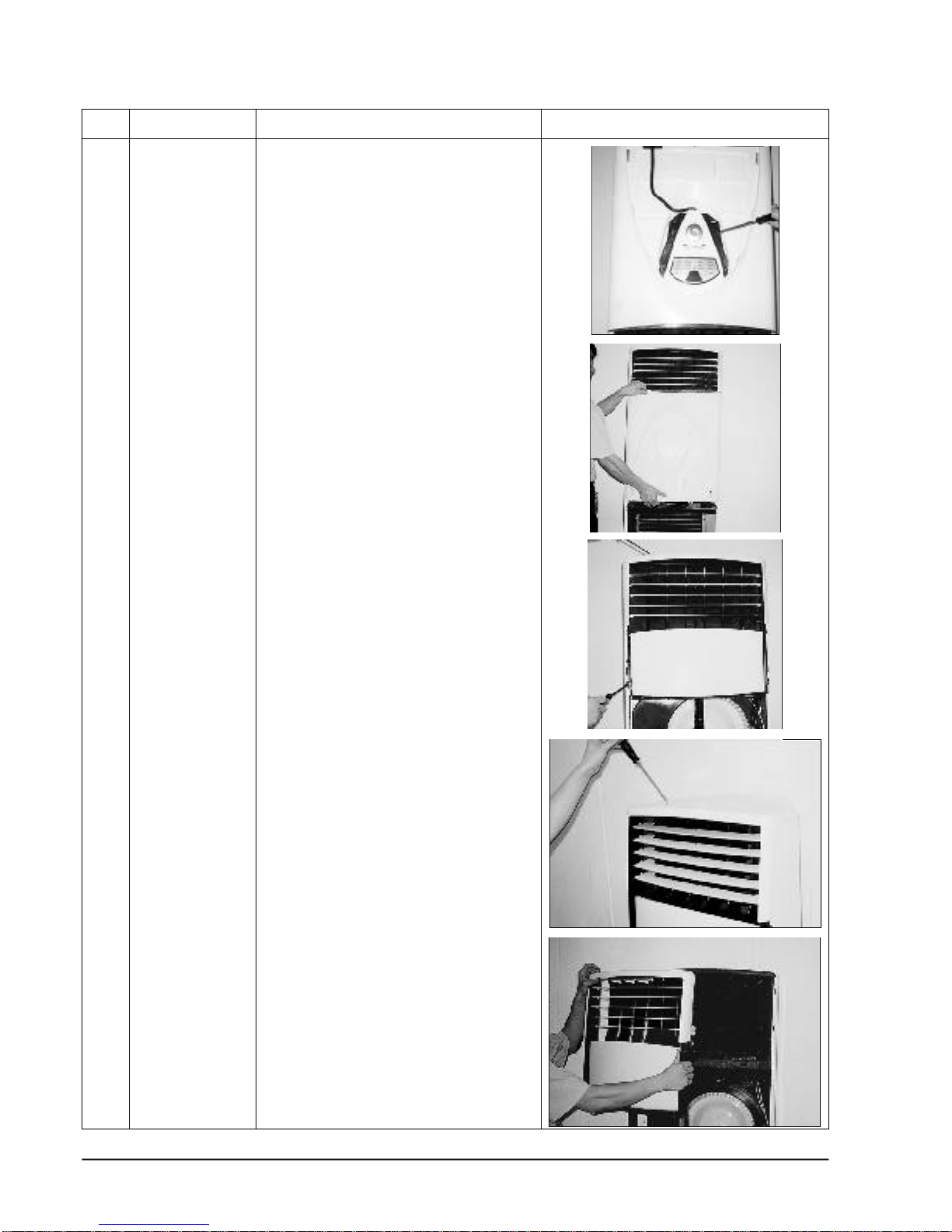
5) To remove the Deco Low, remove the right
and left side two screws, and then seperate the wire connector.
6) Remove the four screws, and remove the
cover top. Then seperate the connector
wire
7) Remove the six screws, and pull the
upward cover top PCB.
Disassembly and Reassembly
4-3
Samsung Electronics
No Parts Procedure Remark
8) Loosen the right and left side two screws,
and then push the upward cover front.
9) Remove the five screws,and then remove
the seven screws on the Duct up.
Disassembly and Reassembly
4-4
Samsung Electronics
No Parts Procedure Remark
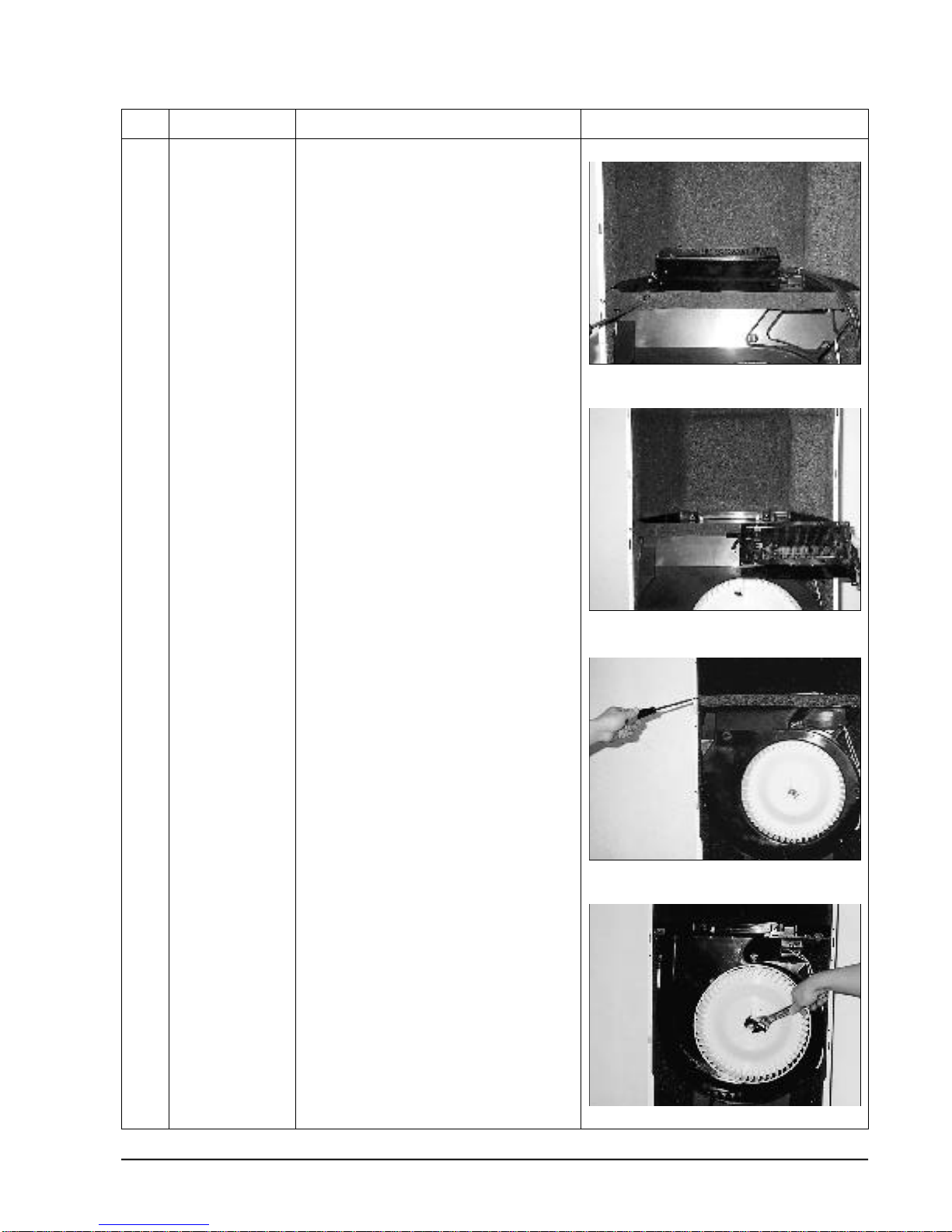
10) Loosen one bolt to remove the blower.
11) Loosen the five locking screws, and
remove the lower duct on the front side.
Remove the left and right side two screws,
and the upper side two screws.
And then seperate the shutter body
4-5
Samsung Electronics
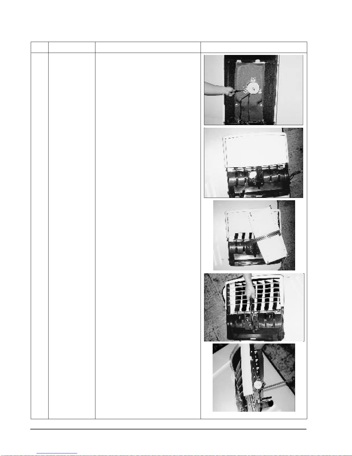
4-2 Outdoor Unit
No Parts Procedure Remark
1) Loosen the seven screws on the cover top,
and remove the cover top.
2) Loosen the two screws on the cover
control, and remove the cover control.
3) Loosen the six screws in the side cabinet,
and remove the side cabinet.
4) Connection of the control box wiring.
Troubleshooting pro c e d u re s
1 • Check the items to check first time.
2 • Check the self-diagnostic mode and action method.
3 •
Check in detail the troubled parts according to the sequence of ”trouble shooting by the phenomena”.
Samsung Electronics
5-1
5. Troubleshooting
5-1 The items to be checked first time
1) Is proper the power voltage ?
The power voltage shall be of 187V-253V 50Hz.
2) Is the cable connected correctly between the indoor and outdoor unit?
The indoor and outdoor units shall be connected with 8wires including the gro u n d i n g .
Check whether the wires of indoor and outdoor units are connected with the correct wire no. and
terminal board no.
3) The phenomena in the following table is not related to the fault of air conditioner.
No
1
2
3
4
5
6
7
- Durning the heating, the compressor and outdoor
unit fan motor operate but indoor unit fan motor
does not operate.
- Durning the heating, the outdoor unit fan motor
repeats start/stop or even the compressor repeats
the starts the start snd stop.
- Durning the heating operation, the lamp “on deice”
is on at the control panel and the compressor
oprates.
-The compressor repeates the stop and start with the
interval of several minutes durning dry.
- The temperature is not adjusted durning the auto,
dry, turbo and long and fan operation.
- Fan speed is not adjusted durning the auto, dry, turbo
and long operation.
-
Heating operaation
The compressor does not operated even though the set
t e m p e r a t u re is set higher than the indoor temperature.
-
Cooling operation
The compressor does not operated even though the set
t e m p e r a t u re is set lower than the indoor temperature .
Phenomena
-This is the function to prevent the cooling air incoming to the
indoor, where the temperature of indoor evaporator reaches 27°C,
the indoor fan motor operates.
- It is the function to prevent the overheating of the indoor
evapolator, where the temperature of indoor unit heat exchanger
reaches 52°C, the normal operation is done.
- The deice operation is being performed in order to melt the frost
by outdoor unit and its maximum time is 9 minutes.
- At the dry operation, the set temperature and the indoor
temperature are compared to adjust the compressor start/stop
time in order to dehumidify.
- The set temperature is automatically set durning the auto, dry
and long operation.
- The wind blow operation is the mode to circulate the indoor air.
-
The fan speed is automatically adjusted durning the auto, dry,
turo and long operation.
-
The operation of compressor is delayed for 3minutes for the
protection of compressor when it is off and on again.
- The compressor operates nomally after 3 minutes even the lnitial
power is on.
Description
Samsung Electronics
5-2
5-2 Display of the result of self-diagnostic and check items on the control panel
1
2
3
4
5
6
Flickering
(1Hz)
Flickering
(1Hz)
Flickering
(1Hz)
Flickering
(1Hz)
Flickering
(1Hz)
Flickering
(1Hz)
Power
lamp
No.
Te m p e r a t u re
d i s p l a y
Cause Counter measure Remark
E1
E2
E5
E6
E7
EC
- Indoor temperature sensor open
- Indoor temperature sensor short
- Shutter motor defect
- Shutter sensor defact
- Connector wire contact bad
- Indoor evaporator sensor open
- Indoor evaporator sensor short
- Indoor condensor sensor open
- Indoor condensor sensor short
- Connector wire contact bad
- Electric heater sensor open
- Electric heater sensor short
- Electric heater overheated
- Indoor fan motor stocked
- Indoor fan motor fault
“E1”AND “E2” ARE DISPLAYED ON THE TEMPERATURE DISPLAY ONLY WHEN THE OPERATION STOPS.
- Check short/open of PCB parts
- Replacement of temperature sensor
- Replacement of shutter motor
- Replacement of shutter sensor
- Replacement of connector wire
- Check short/open of PCB parts
- Replacement of temperature sensor
- Check short/open of PCB parts
- Replacement of temperature sensor
- Check the overheating sensor
- Remove the cause of the indoor fan
motor stocking
- Replacement of indoor fan motor
- Check short/open of PCB parts
- Replacement of sensor
- Replacement of connector wire
APH180CD
APH180HD
APH180ED
APH180CD
APH180HD
APH180ED
APH180HD
APH180ED
APH180HD
APH180ED
APH180ED
APH180ED
Samsung Electronics
5-3
5-3 Trouble shooting by phenomena
5-3-1 When it is not Power on.(When it is not display)
1) Trouble cause
1 When the power voltage is out the operating range or the power cable contact is bad.
2 The transformer is defect or it’s connection is bad.
3 The fuse of main PCB is broken or the PCB with a defect.
4 The panel PCB has it’s defect.
• The knob switch with a poor assembly, V.F-display defect.
2) Check items
1 Is the power voltage normal?(AC 187V~AC 253V)
2 Is the contact of power cable good?
3 Is the power fuse(F701, F702) AND PCB fuse(F101)not disconnected?
4 Is the contact of connector at primary and secondary side of power transformer?
5 Is the output voltage of IC08(KA7812) normal?(DC 11.5~DC 12.5V)
6 Is the output voltage of IC09(KA7805) normal?(DC 4.5~DC 5.5V)
7 Is the connection of harness(wire connector- c o n t rol)of main PCB panel good?
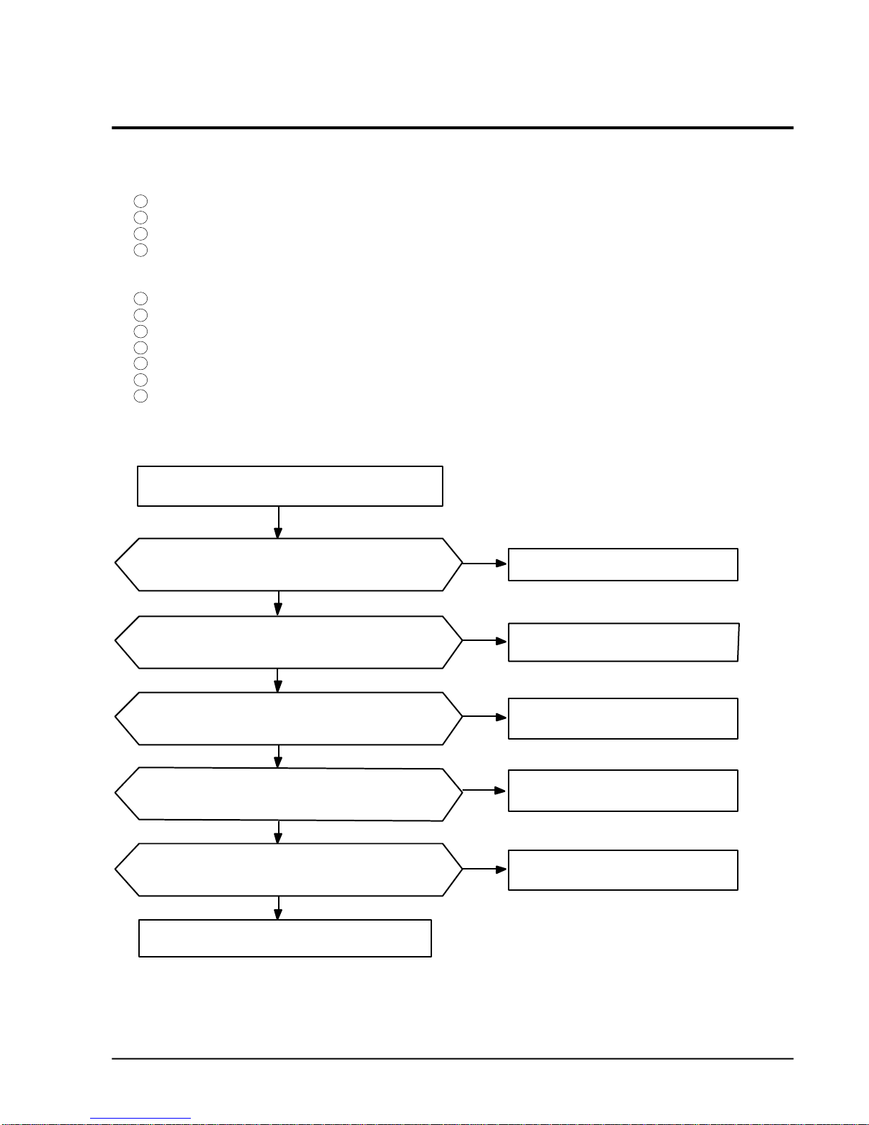
3) Sequence of check
Tu rn off the power, and then turn it on in 5 seconds.
Is the display part on dose the door operate
when pressing the start key?
Is the voltage of the power input part(CN71 red-white)
AC 187~AC 253V?
Is the output voltage of IC08, and IC09 normal?
(IC08=12V, RIC09=5V)
Is the secondary voltage of power transformer correct?
blue-white:AC14~17V,red-red:AC4~5V black-white:AC14~17V
Dose the remocon receive the singnal correctly?
Normal operation of set.
Y
N
N
N
N
N
Y
Y
Y
N
Check the connection harness of indoor and
replace.
Check the power trancsfornmer and replace it.
Check the main PBC and replace it.
Check the knob key.
Replace it due to the defact of main PCB.
 Loading...