

Samsung AG042KSVANH, AG056KSVANH, AG070KSVANH Installation Manual
DVM CHILLER
Installation manual
AG042KSV✴✴✴ / AG056KSV✴✴✴ / AG070KSV✴✴✴ Series
ŷ Thank you for purchasing this Samsung Product.
ŷ Before operating this unit, please read this Insatallation manual carefully and retain it for future
reference.

2
English
Contents
INSTALLATION
Safety information 3
Preparing for installation 8
Specications of the non-pump models 8
Specications of the pump integrated models 9
DVM CHILLER Classication 10
Moving the product 10
Center location 11
Accessories (Basic specication) 11
Field Supply 11
Selecting installation location 12
Required space for installation 14
Base construction and installation 16
Supporting base construction 16
Product installation 17
Base mount and anchor bolt position 17
Examples of draining work 17
Installation precautions 18
Installing the wind/snow prevention duct 20
Installing the discharge duct around the obstacles 20
Installing the discharge duct in cold regions 20
Installing the discharge duct in regions with strong wind 21
Water pipe installation 22
Water pipe diagram 22
Water pipe installation 23
Securing water storage 26
Water pipe installation 26
Startup 27
Maintenance 27
Using the pump 27
Pump performance chart 28
Fault nding 29
ELECTRICAL WORK
Electrical wiring work 31
Circuit breaker and power cable specication 31
Power and communication cable conguration 32
Connecting the power cable 33
Connecting the communication cable 34
External contact wiring work 34
Selecting solderless ring terminal 40
Connecting the power terminal 41
Fixing the power cable 43
Fixing the ground cable 43
Withdrawing the power cable 44
Installing the Solution device 44
Grounding work 44
Setting key function 46
Setting hydro controller option 46
How to set hydro controller option 49
Setting inverter controller option 55
BEFORE OPERATION
Check points after installation 61
Trial operation 62
Trial operation for each CHILLER unit 63
MAINTENANCE
Maintenance 65
Name of the parts 65
Water pipe installation 66
Water maintenance standard 68
Maintaining plate type heat exchanger 70
Stopping during winter time 71
Stopping for a long time 71
Inspection for normal operation 72
Chilled/Heating water ow rate range 72
Chilled water management 73
Water temperature range 74
Freeze prevention 74
Error display 77
Error history display 80
Air tightness test and vacuuming 80
Important information regulation regarding the refrigerant used 81
Troubleshooting 83
Periodic maintenance 85
Quick Smart Features 88
COMMISSION REGULATION (EU) No 813/2013 I) 90
ECODESIGN REQUIREMENTS FOR SPACE HEATER
II)
90
COMMISSION DELEGATED REGULATION (EU) No 811/2013
i)
105
PRODUCT FICHE (ENERGY LABELLING OF SPACE HEATERS)
ii)
105
PRODUCT FICHE (ENERGY LABELLING OF PACKAGES OF SPACE HEATER)
iii)
105
PRODUCT FICHE (ENERGY LABELLING OF TEMPERATURE CONTROLS)
iv)
105
PRODUCT FICHE (ENERGY LABELLING OF SPACE HEATERS)
ii)
106
PRODUCT FICHE (ENERGY LABELLING OF PACKAGES OF SPACE HEATER)
iii)
106
PRODUCT FICHE (ENERGY LABELLING OF TEMPERATURE CONTROLS)
iv)
106
INSTALLATION
3
English
Safety information
DVM Chiller uses R-410A refrigerant.
ŷ When moisture or foreign substances enter into the
refrigerant pipe using R-410A, it may affect the
performance and reliability of the product. Safety
precautions must be obeyed when installing the
refrigerant pipe.
ŷ Since R-410A is an azeotrope refrigerant, it must be
charged in liquid phase. (A blend of the refrigerant
may change if you charge in vapor phase which
could cause product malfunction.)
The manufacturer is not responsible for any installation
or performance problem of the load side indoor unit
and water pipes.
ŷ Product for low temperature (below 5°C) must use
anti-freeze to manage freezing point (concentration
of anti-freeze) according to usage range.
ŷ Freezing point of anti-freeze should be checked
periodically after installation during usage. (once a
year or more)
ŷ Maintain the temperature of chilled/heating water to
recommended range for stable operation.
The manufacturer is not responsible for freezing and
bursting of heat exchanger occurred by errors on
installation.
After completing the installation and test operation,
explain to the user how to use and maintain the
product. Also, hand over this installation manual so that
it can be stored by the user.
The manufacturer of DVM Chiller is not responsible
for the incidents occurred by improper installation.
Installer is responsible for any installation related
claims from the user occurred by neglecting warnings
and cautions stated in this manual.
Generally, DVM Chiller should not be relocated after
installation. But when it has to be relocated for
inevitable reasons, please contact Samsung's qualied
dealers for DVM Chiller.
WARNING
Hazards or unsafe practices that may result in severe
personal injury or death.
CAUTION
Hazards or unsafe practices that may result in minor
personal injury or property damage.
Follow directions.
Do NOT attempt.
Make sure the machine is grounded to prevent
electric shock.
Unplug the power plug from the wall socket.
Do NOT disassemble.
For operation
WARNING
Do not use water containing chemicals such as
chlorine for chilled/heating water as it can cause
corrosion on stainless steel or copper.
ŷ This may result in product malfunction.
Do not block air inlet or outlet of the product.
ŷ It may cause performance decrease or
malfunction of the product.
Do not attempt to disassemble, modify, or repair
the product.
ŷ Failure to do so may result in water leakage,
electric shock or re. Contact the service center.
Do not use the product where oil particles such as
cooking oil and machine oil exist.
ŷ There are potential risks of electric shock or re.
Do not use the product where smokes consisted
by oil particles, such as kitchen, ammable gas,
corrosive gas, or metallic dust exist.
ŷ Failure to do so may result in re or
phenomenon.
INSTALLATION
Safety information
4
English
Do not operate the product with power switch or
circuit breaker.
ŷ Potential risk of electric shock or re.
ŷ If automatic blackout restore is set, fan may spin
suddenly and it may cause injury.
If fuse load switch is used, do not use fuse in
incorrect capacity.
ŷ Usage of wire may result in product malfunction
or re.
Do not use ammable gas (such as hair spray or
insecticide) near the product.
ŷ There are potential risks of electric shock or re.
If there is any problem (such as burning smell),
stop the operation and close the circuit breaker.
ŷ Otherwise, it may cause product malfunction,
electric shock, or re. Contact the service center.
Use chilled/heating water which is appropriate
according to water maintenance standard.
ŷ Deterioration of water may cause water leakage.
Contact the merchandise or service center to clean
inside of the product.
ŷ Error on selecting cleaner and cleaning the
product may harm rubber part and cause water
leakage.
ŷ If the cleaner reaches to electric parts or motor,
it may cause product malfunction, smoke, or re.
CAUTION
Do not use the product for specic purpose.
ŷ It may affect performance, quality, or life of
preservation of precision machinery, food, art
work, etc., and breeding animal or plants.
Do not use the holder which is worn out for
longtime usage.
ŷ It may cause injury due to falling down of the
product.
Do not step onto the product or place any objects
on the product.
ŷ It may cause injury due to falling down of the
product.
Do not operate the product with the cover of
exterior or electric box opened.
ŷ It may cause electric shock or re.
Do not place any objects that are not allowed to be
wet.
ŷ It may get wet by dripping water caused
by product or refrigerant pipe freezing,
contaminated air lter, blocked drain valve.
Do not change settings for protection device.
ŷ It may cause re.
Do not use chilled/heating water for drinking.
ŷ It is harmful for humans.
ŷ For hot water supply, use undirective heat
exchange.
Do not wash the product with water.
ŷ It may cause electric shock.
Do not operate protect devices forcibly.
ŷ This may result in re or explosion.
Do not touch high temperature part such as
compressor and refrigerant pipe.
ŷ It may cause burns.
Do not touch inlet or aluminum plate.
ŷ It may cause injury.
INSTALLATION
5
English
When outdoor temperatre drops below zero, take
appropriate countermeasures for frozen damage.
ŷ Freeze protection such as using brine, heater,
pump operation, etc. is necessary.
ŷ Drain all water and cut-off the power supply
when the product is not operated during winter
time.
Use appropriate refrigerant and refrigerant oil.
ŷ This may result in re or explosion.
Stop the operation and close the circuit breaker
while repair service.
ŷ Otherwise, it may cause electric shock or injury.
Be aware of step board while working on high
place.
ŷ This may result in injury by falling down if the
step board is not stable.
Use chilled/heating water which is appropriate
according to water maintenance standard.
(Refer to page 68 for water maintenance standard.)
ŷ Deterioration of water may cause water leakage.
Follow regulations for disposing brine, cleaner, and
refrigerant.
ŷ It is against the law to dispose illegally.
For installation
WARNING
Do not install the product by users.
ŷ It may result in water leakage, electric shock,
or re if installation is not precise. Contact the
merchandise or service center.
Consult qualied installer or dealer for installation.
ŷ When the installation is done by unqualied
people, it may cause water leakage, electric
shock or re.
Installation should be done by following the
installation manual accurately.
ŷ When installation is not done properly, it may
cause water leakage, electric shock or re.
Do not install the eld supply parts by users.
ŷ Do not use any other product other than the
manufacturer recommended. It may result in
water leakage, electric shock, or re if installation
is not precise. Contact the merchandise or
service center.
Do not move or reinstall the product by users.
ŷ It may result in water leakage, electric shock,
or re if installation is not precise. Contact the
merchandise or service center.
Do not close the circuit breaker for protect devices.
ŷ Otherwise, a re may occur.
Do not install power cables between the products.
ŷ It may cause re.
Make sure to install the product in a place strong
enough to withstand its weight.
ŷ Otherwise, it may result in falling down,
vibration, noise of the product.
Install the product securely to resist strong wind or
earthquake.
ŷ Otherwise, it may result in falling down,
vibration, noise of the product.
Fix the product securely to resist natural
phenomenon such as earthquake.
ŷ If the product is not properly xed, it may fall
down and cause an accident.
ŷ When installing the unit in a small area, take
measure to keep the refrigerant concentration
from exceeding allowable safety limits in case
of refrigerant leakage. Consult the dealer for
precautionary measure before the installation.
ŷ When refrigerant leaks and exceed dangerous
concentration level, it may cause suffocation
accidents.

INSTALLATION
Safety information
6
English
Check the followings before installation and repair/
maintenance service.
ŷ Before brazing, remove dangerous and/or
ammable things around workplace that may
cause an explosion and re.
ŷ Before brazing, remove the refrigerant within
the pipe or the product.
ŷ If you perform welding while refrigerant is in
the pipe, it may increase the pressure of the
refrigerant and cause the pipe to burst. If the
pipe bursts or explodes, it may cause severe
injury to the installer.
ŷ Use the nitrogen gas to eliminate oxide inside
the pipe during brazing.
Electric work must be done by qualied people,
complying the national wiring regulations and
installed according to the instruction stated in the
installation manual and must comply regulated
electrical specication.
ŷ Capacity shortage on the power circuit or
improper installation may cause electric shock or
re.
Wiring must be connected with the designated
wires and it must be xed securely so that it does
not apply any external force to the connection part
of the terminals.
ŷ If connection or xation is not properly done, it
may cause heat generation or re.
Neatly arrange the wires in the electrical parts to
make sure that electrical cover is closed securely
without any gaps.
ŷ If the cover is not properly closed, heat may
generate on the terminal and cause electric
shock or re.
Exclusive circuit breaker (MCCB, ELB) must be
installed to the power supply.
ŷ Use ELCB that has harmonic wave prevent
function since the product uses inverter
compressor.
ŷ If the auxiliary circuit breaker is not installed,
power will not be cutoff in case of overcurrent
or current leakage and cause electric shock or
re.
ŷ Do not use damaged parts. Otherwise, a re or
electric shock may occur.
You must cut-off the power before you work
on, or adjust any power supply part for product
installation, maintenance, repair or any other
services.
ŷ This may result in electric shock.
ŷ Even when the power is off, it is very dangerous
to touch the inverter PCB and the fan PCB since
high pressure DC voltage is charged for those
parts.
ŷ When replacing/repairing the PCB, cut-off
the power and wait until the DC voltage is
discharged before replacing/repairing them.
(Wait for more than 15 minutes to allow those
parts to be fully discharged.)
You must ventilate the room if the refrigerant gas
leaks during the installation.
ŷ Toxic gas can be generated when the refrigerant
gas gets in contact with ammable substance.
Use chilled/heating water which is appropriate
according to water maintenance standard.
(Refer to page 68 for water maintenance standard.)
ŷ Deterioration of water may cause water leakage.
Contact the merchandise for refrigerant stagnating.
ŷ When refrigerant leaks and exceed dangerous
concentration level, it may cause suffocation
accidents. When installing the unit in a small
area, take measure to keep the refrigerant
concentration from exceeding allowable safety
limits in case of refrigerant leakage.
Follow regulations for disposing brine, cleaner, and
refrigerant.
ŷ It is against the law to dispose illegally, and also
harmful for humans and environment.
INSTALLATION
7
English
Wiring must be connected with the designated
wires and it must be xed securely so that it does
not apply any external force to the connection part
of the terminals.
ŷ If connection or xation is not properly done, it
may cause heat generation or re.
Please connect ground wire.
ŷ If the ground wire is not properly xed, there is
potential risk of electric shock or re.
ŷ Do not connect the grounding cable to a gas
pipe, water pipe, lightening conductor or the
grounding cable of the telephone.
CAUTION
Drain system must be constructed according to this
installation manual so that condensation water
drains properly, and drain system should be kept
warm to prevent dew condensation.
ŷ When water management is not done properly,
water leakage may occur and cause property
damage.
Install the power cable and communication cable
of the product at least 1.5m away from the electric
appliances and install it at least 2m away from the
lightning conductor.
ŷ Even if the cables are installed more than 2 m
away from electronics, noise can be generated
from them depending on the status of the
electric wave.
Do not leave any obstacles around the inlet and
outlet of the product.
ŷ It may cause product failure or other accidents.
Do not install the product in following places.
ŷ A place where noise and warm air of the product
may disturb neighbors
- It may cause property loss.
ŷ A place full of mineral oil, place where oil
scatters or with oil vapors such as a kitchen
- Plastic parts may get damaged and cause
water leakage, or maybe even cause product
to fall down.
- The performance of the heat exchanger may
decrease or cause product failure.
ŷ A place near exhaust pipes or ventilation outlet
where corrosive gas such as ammonia gas or
sulfurous acid gas are being generated
- Copper pipe and connection parts may corrode
causing refrigerant leakage.
ŷ A place with a machine that generates
electromagnetic waves
- Electromagnetic waves may cause problems in
control system and product may not operate
normally.
ŷ A place where there is a danger of combustible
gas leakage or the place where thinner or
gasoline is handled
There is a risk of re or explosion.
ŷ A place with airborne carbon ber or ammable
dust
ŷ A place near seashore or hot spring where there
is risk of product corrosion
Install MCCB for each product.
ŷ Use ELCB that has harmonic wave prevent
function since the product uses inverter
compressor.
ŷ It may cause electric shock or re if more than
two products are installed on one MCCB.
Make sure to install drain pipe for draining
performed correctly.
ŷ If the installation is not done properly,
water leakage may occur and cause product
malfunction.
This appliance is not intended for use by persons
(including children) with reduced physical, sensory
or mental capabilities, or lack of experience and
knowledge, unless they have been given supervision
or instruction concerning use of the appliance by a
person responsible for their safety. Children should be
supervised to ensure that they do not play with the
appliance.
For use in Europe : This appliance can be used by
children aged from 8 years and above and persons
with reduced physical, sensory or mental capabilities
or lack of experience and knowledge if they have been
given supervision or instruction concerning use of the
appliance in a safe way and understand the hazards
involved. Children shall not play with the appliance.
Cleaning and user maintenance shall not be made by
children without supervision.
INSTALLATION
8
English
Preparing for installation
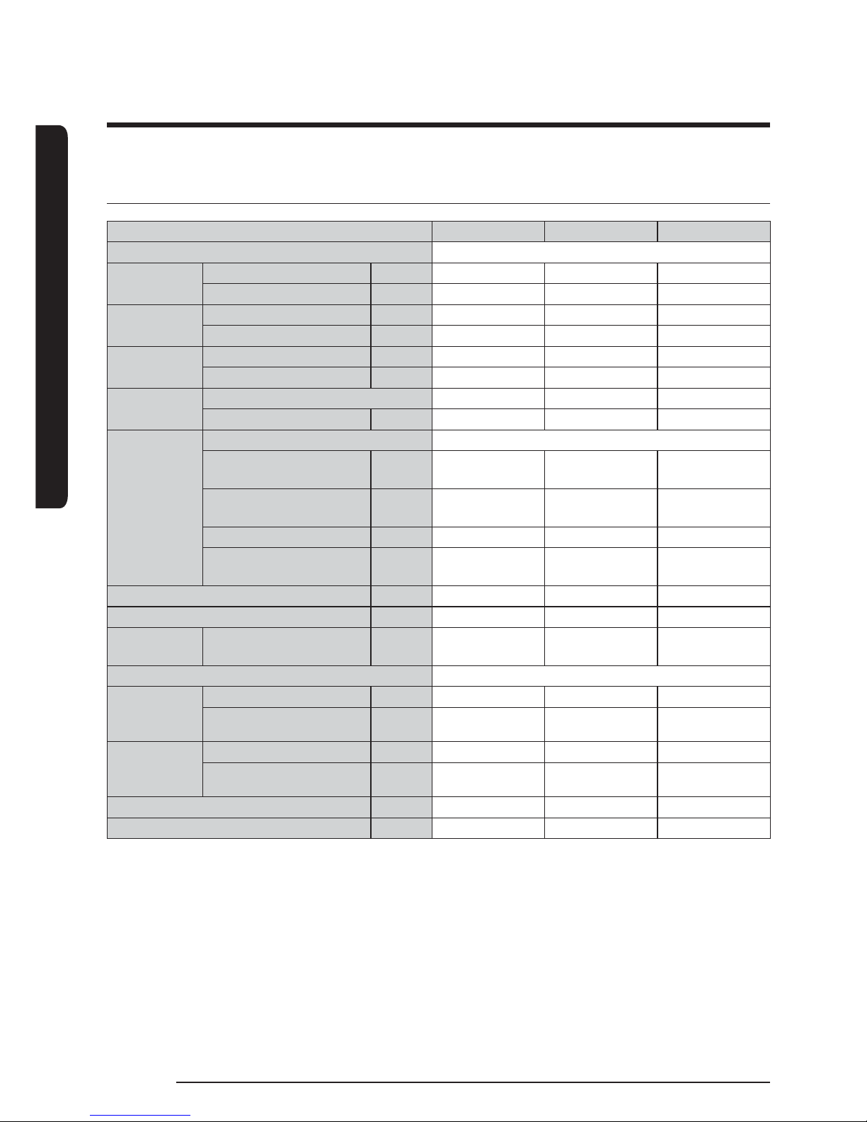
Specications of the non-pump models
Model AG042KSVANH AG056KSVANH AG070KSVANH
Power supply
3 Phase 4 Wires 380 ~ 415 V, 50/60 Hz
Capacity
Cooling (Rated) kW
42 56 65
Heating (Rated) kW
42 56 69.5
Power
consumption
Cooling (Rated) kW
12.35 18.67 26.0
Heating (Rated) kW
11.83 17.50 24.39
Operating
current
Cooling (Rated) A
19.6 29.6 41.2
Heating (Rated) A
18.8 27.8 38.7
Refrigerant
Type
R-410A R-410A R-410A
Charging amount kg
18 18 18
Water
side heat
exchanger
Type
Plate type heat exchanger
Flow rate
(Cooling/Heating)
LPM
120/120 160/160 186/200
Maximum operating
pressure
MPa
1.0 1.0 1.0
Head loss kPa
60 100 120
Inlet·Outlet connected
pipe size
A
40 40 50
Minimum water quantity L
294 392 490
Net weight kg
446 446 465
Net dimension W X H X D mm
1795 X 1695 X
765
1795 X 1695 X
765
1795 X 1695 X
765
Remote control
Module Control
Water outlet
temperature
range
Cooling (If using brine) °C
5 ~ 25 (-10 ~ 25) 5 ~ 25 (-10 ~ 25) 5 ~ 25 (-10 ~ 25)
Heating °C
25 ~ 55 25 ~ 55 25 ~ 55
Surrounding
temperature
range
Cooling °C
-15 ~ 48 -15 ~ 48 -15 ~ 48
Heating °C
-25 ~ 43 -25 ~ 43 -25 ~ 43
MCA A
32 46 58
MFA A
40 60 75
1) Standard for rated cooling capacity: chilled water inlet/outlet temperature 12/7°C, outdoor 35°C DB, 24°C WB
2) Standard for rated heating capacity: heating water inlet/outlet temperature 40/45°C, outdoor 7°C DB, 6°C WB
3) When using brine, maintain the concentration according to temperature. (Refer to page 76.)
INSTALLATION
9
English
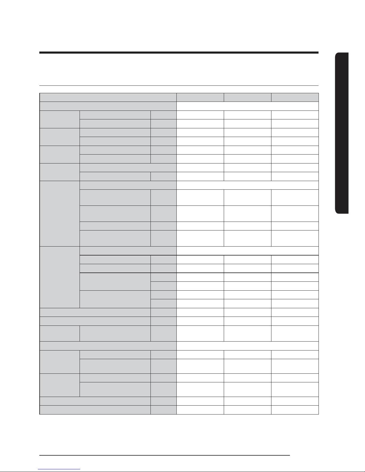
Specications of the pump integrated models
Model AG042KSVGNH AG056KSVGNH AG070KSVGNH
Power supply
3 Phase 4 Wires 380 ~ 415 V, 50/60 Hz
Capacity
Cooling (Rated) kW
42 56 65
Heating (Rated) kW
42 56 69.5
Power
consumption
Cooling (Rated) kW
13.59 20.14 28.26
Heating (Rated) kW
12.77 18.48 25.84
Operating
current
Cooling (Rated) A
24.2 34.2 45.8
Heating (Rated) A
23.4 32.4 43.3
Refrigerant
Type
R-410A R-410A R-410A
Charging amount kg
18 18 18
Water
side heat
exchanger
Type
Plate type heat exchanger
Flow rate
(Cooling/Heating)
LPM
120/120 160/160 186/200
Maximum operating
pressure
MPa
1.0 1.0 1.0
Head loss kPa
60 100 120
Inlet·Outlet connected
pipe size
A
40 40 50
Pump
Type
End-Suction
Input x n kW
1.68 1.68 1.68
Output x n W
1.45 1.45 1.45
Normal Water Flow rate
(Cooling/Heating)
LPM
120/120 160/160 186/200
l/s
2.0/2.0 2.7/2.7 3.1/3.3
External Static Pressure
(Max.)
mAq
22.4 / 22.4 15.3 / 15.3 10.2 / 10.2
kPa
220 / 220 150 / 150 131 / 100
Minimum water quantity L
294 392 490
Net weight kg
472 472 493
Net dimension W X H X D mm
1795 X 1695 X
765
1795 X 1695 X
765
1795 X 1695 X
765
Remote control
Module Control
Water outlet
temperature
range
Cooling (If using brine) °C
5 ~ 25(-10 ~ 25) 5 ~ 25(-10 ~ 25) 5 ~ 25(-10 ~ 25)
Heating °C
25 ~ 55 25 ~ 55 25 ~ 55
Surrounding
temperature
range
Cooling °C
-15 ~ 48 -15 ~ 48 -15 ~ 48
Heating °C
-25 ~ 43 -25 ~ 43 -25 ~ 43
MCA A
39 53 65
MFA A
50 60 75
1) Standard for rated cooling capacity: chilled water inlet/outlet temperature 12/7°C, outdoor 35°C DB, 24°C WB
2) Standard for rated heating capacity: heating water inlet/outlet temperature 40/45°C, outdoor 7°C DB, 6°C WB
3) When using brine, maintain the concentration according to temperature. (Refer to page 76.)
INSTALLATION
Preparing for installation
10
English
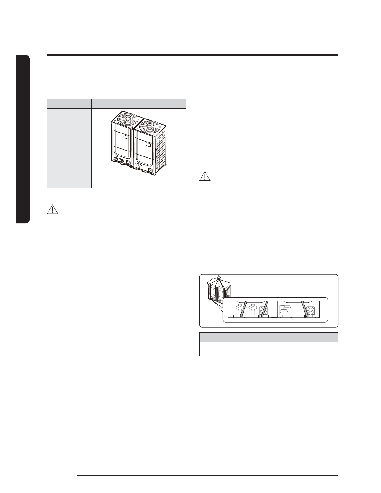
DVM CHILLER Classication
Classication DVM CHILLER
Appearance
Applied model
AG042/056/070KSV Series
CAUTION
ŷSafely store or dispose the packaging materials.
- Sharp metals such as nails or wooden material
packaging that may break into pieces become a
cause for personal injury.
- Make sure to store or dispose the vinyl type
packaging material to keep it out of reach of
children. Children may put them over their face,
which is very dangerous since it may lead them
to suffocation.
Moving the product
fSelect the moving path in advance.
fBe sure that moving path can support weight of the
product.
fDo not slant the product more than 30˚ when
carrying it.
(Do not lay the product down in sideways.)
fSurface of the heat exchanger is sharp. Be careful not
to get injured while moving the product.
CAUTION
ŷYou must use square holes in the base of the
product when moving the product.
1 When moving with a crane
fFasten the wire rope using square holes of the
product as shown in the gure.
- To protect damage or scratches, insert a piece of
cloth between the product and the wire rope.
- Insert hanging softening material to prevent load
from the rope on top of the product.
AB C
Model name Rope's Location
AG
✴✴✴
KSVA Series B + C
AG
✴✴✴
KSVG Series A + C

INSTALLATION
11
English
CAUTION
ŷDo not hang the rope on side of the water pipe.
The rope may force the water pipe to deformed or
damaged.
2 When moving with a forklift
fCarefully insert the forklift forks into the forklift
holes at the palette.
fBe careful with the forklift from damaging the
product.
Center location
A
B
A
C
B
C
Model name A B C
AG042KSVANH 1020 380 590
AG056KSVANH 1020 380 590
AG070KSVANH 1020 380 590
AG042KSVGNH 950 370 550
AG056KSVGNH 950 370 550
AG070KSVGNH 950 370 550
Accessories (Basic specication)
fYou must keep following accessories not to be lost
during installation.
fHand over the installation manual to the customer
after nishing the installation.
Installation manual Installation check card
Field Supply
fStrainer
Maximum
operating
pressure
Water pipe connection part
AG042/056
✴✴
AG070
✴✴
1.0 MPa 40 A (1-1/2") 50 A (2")
Mesh size Material (Strainer/Mesh)
50 Mesh SUS304
INSTALLATION
12
English
Decide the installation location, with the consideration
of the following conditions, under user's approval.
fPlace where hot discharge air or noise from the DVM
CHILLER may not disturb the neighbor (Especially in
residential areas, keep the operation hours in mind.)
fPlace where structure can bear the weight and
vibration of the DVM CHILLER
fPlace with at surface where rainwater does not
settle or leak
fPlace where it is not exposed to strong wind
fWell ventilated place with sufcient service place
for repairs and maintenance (Discharge duct can be
purchased separately)
fPlace where it allows easy waterproong and
draining work for the condensation water generated
from the DVM CHILLER during heating operation
fPlace where there is no risk of inammable gas
leakage
fPlace where there is no direct inuence of snow or
rain
fDo not install the product in a place where it will be
directly exposed to sea breeze.
- Consult an installation expert (or company)
since you will need to take extra anti-corrosion
measures if you need to install the product in
a place where it can be exposed to direct sea
breeze. (You have to remove dusts and salinity
on the heat exchanger and apply designated rust
inhibitor more than once a year.)
Sea
Sea breeze
DVM
CHILLER
DVM
CHILLER
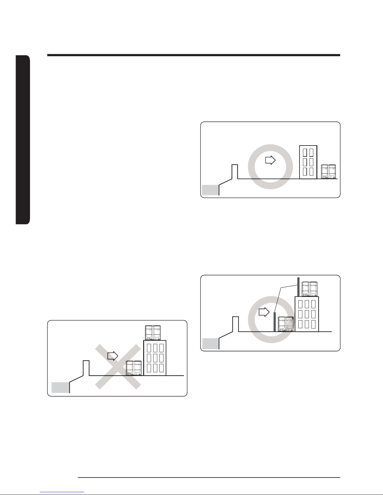
fCaution when installing the product in seashore
- When installing the product in seashore, make
sure to install it behind a structure (such as
building) that can block the sea breeze or install
protection wall around the DVM CHILLER.
Sea
Sea breeze
DVM
CHILLER
- Make sure to install the product in a place where
it allows smooth drainage.
- Protection wall should be constructed with a
solid material that can block the sea breeze
and the height and width of the wall should
be 1.5times larger than the size of the
DVMCHILLER. (You must secure more than
700mm of space between the protection wall
and the DVMCHILLER for air circulation.)
Sea
Sea breeze
DVM
CHILLER
Protection wall
DVM
CHILLER
Selecting installation location

INSTALLATION
13
English
CAUTION
ŷIn regions with heavy snowfall, make sure to install
the DVM CHILLER where there is no concerns of
direct snowfall on the DVM CHILLER. Also, build
higher base support so that accumulated snow does
not block the air inlet or the heat exchanger.
ŷR-410A refrigerant is a safe, nontoxic and
nonammable refrigerant. However, if the place
holds any concerns for exceeding dangerous level
of refrigerant concentration in case of refrigerant
leakage, extra ventilation system is required.
ŷWhen you install the product in a high places such
as roof, install fence or guardrail around it. When
there is no fence or guardrail, service person could
fall.
ŷDo not install the product in places where corrosive
gases such as sulfur oxides, ammonia, and sulfurous
gases are produced. (e.g. Toilet outlet, ventilation
opening, sewage works, dyeing complex, cattle
shed, sulfuric hot spring, nuclear power plant, ship
etc.) When installing the product in those places,
contact an installation specialty store as the copper
pipe and brazing part will need additional corrosion
proof or anti-rust additive to prevent corrosion.
ŷMake sure to keep any inammable materials (such
as wooden materials, oil etc.) around the DVM
CHILLER. When there's re, those inammable
material will easily catch the re and may pass it on
to the product.
ŷDepending on the condition of power supply,
unstable power or voltage may cause malfunction
of the parts or control system.
(At the ship or places using power supply from
electric generator, etc.)
INSTALLATION
14
English
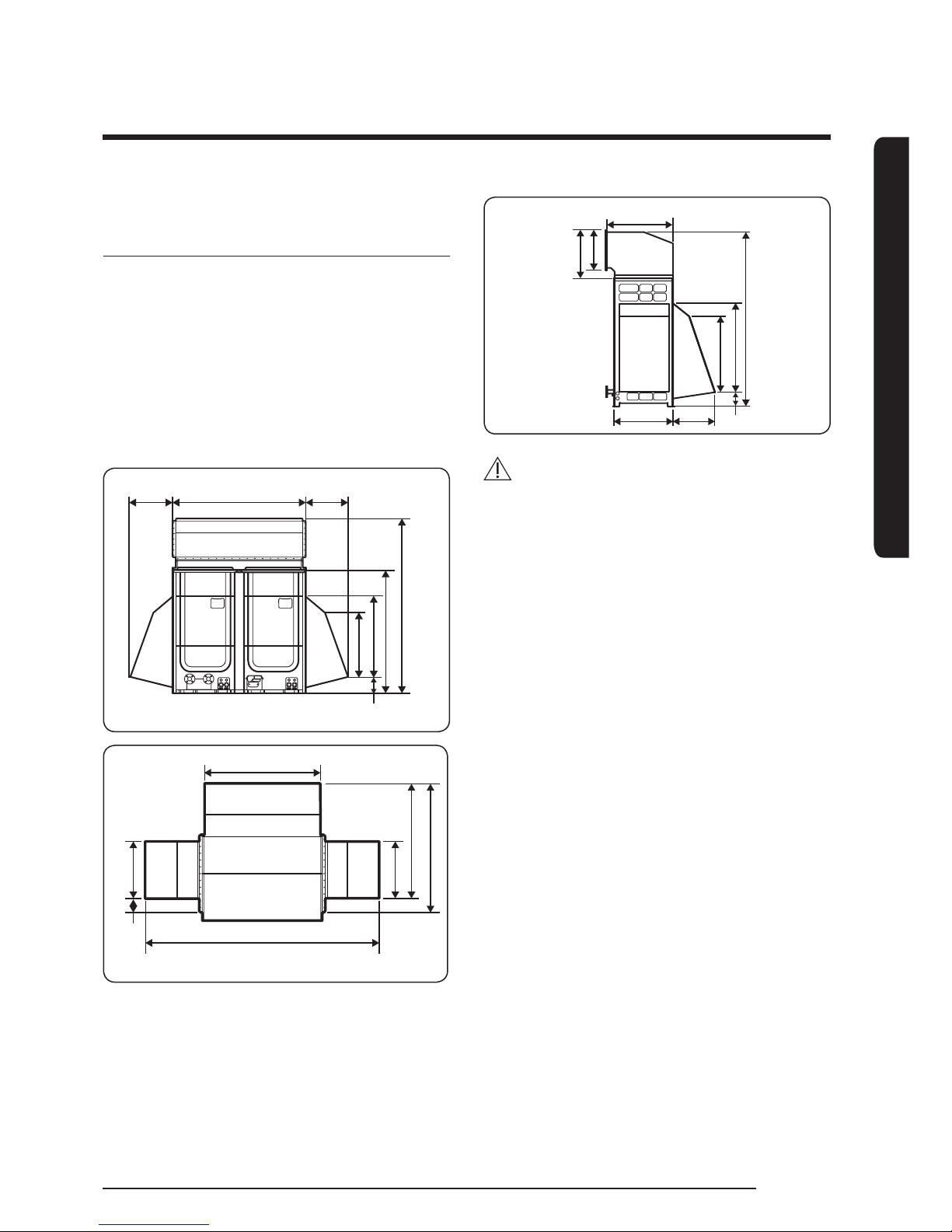
Required space for installation
fSpace requirement was decided based on the
following conditions; Cooling mode, outdoor
temperature of 35°C. Larger space is required if the
outdoor temperature is higher than 35°C or if the
place is heated easily by quantity of solar radiation.
fWhen you secure installation space, consider path for
people and the direction of the wind.
fSecure installation space as shown in the gure,
considering ventilation and the service space.
fIf the installation space is narrow, installer or other
worker may get injured during work and may also
cause a problem with the product.
fIf you install multiple number of DVM CHILLERs in
one space, make sure to secure enough ventilation
space if there's any walls around the product that
may disturb the air ow. If enough ventilation space
is not secured, the product may malfunction.
fYou could install the DVM CHILLERs with 100 mm
of space between each unit, but performance may
decrease depending on the installation environment.
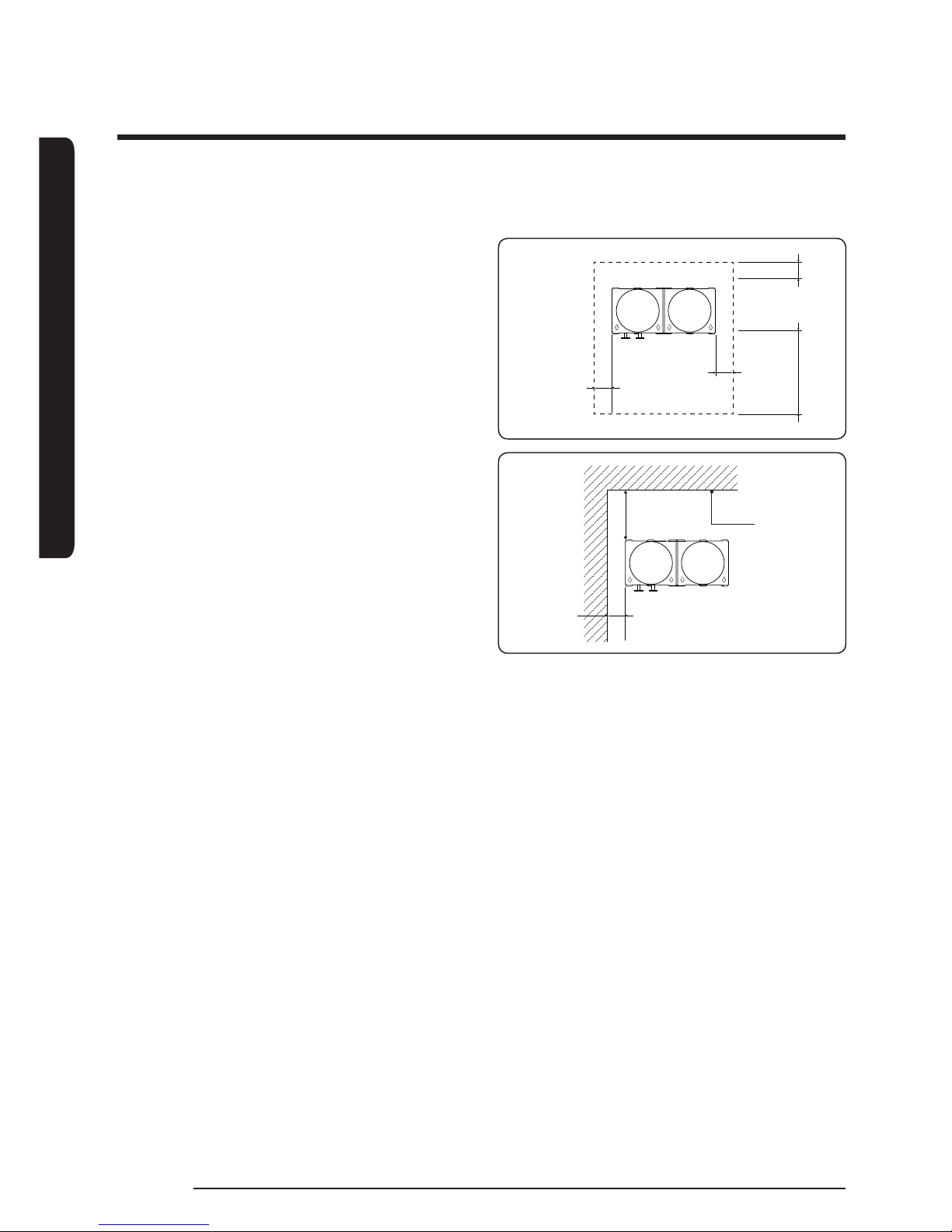
1 Single installation
Unit: mm
Front side
100 or more
100 or
more
500 or more (S1) 100 or
more (S2)
<Case 1>
Front side
100 or
more
300 or
more
Height of
the wall is
unlimited
<Case 2>
INSTALLATION
15
English
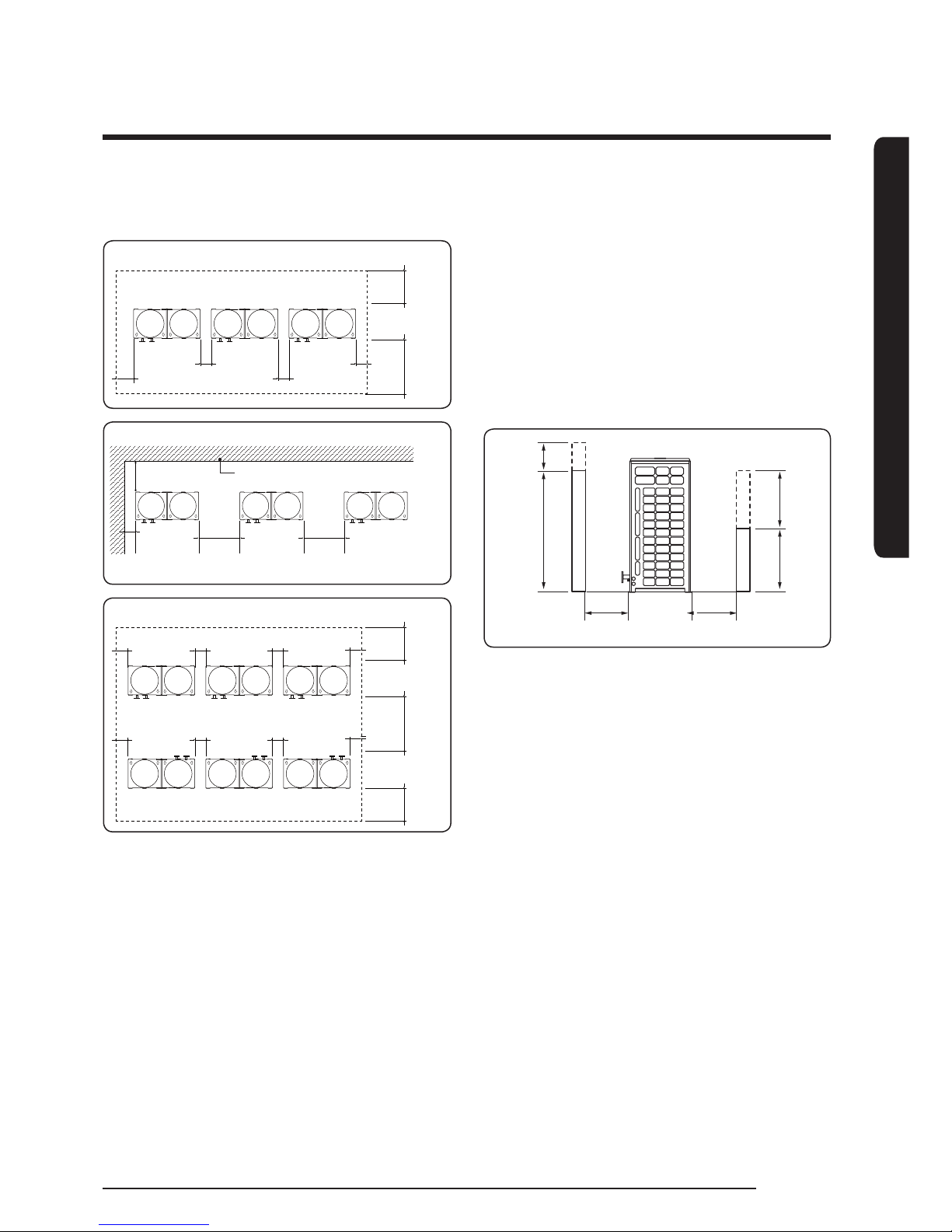
2 Module installation
Unit: mm
Front side
100 or more
200 or more 100 or more
100 or more
300 or
more (S2)
500 or
more (S1)
<Case 1>
<Case 2>
400 or
more
400 or
more
200 or
more
Front side
300 or more
Height of the wall is unlimited
Front side
Front side
100 or more
100 or more
100 or
more
100 or
more
100 or more
100 or more
100 or
more
100 or
more
500 or
more
500 or
more
600 or
more
<Case 3>
f Installing by <Case 1> or <Case 3>
- Height of the wall on the front side should not
be higher than 1500mm.
- Height of the wall on the air inlet side should not
be higher than 500mm.
- Height of the wall on the side is not limited.
- If the height of the wall exceeds by certain value
(h1, h2), additional clearance [(h1)/2, (h2)/2 : Half
of the exceeded distance] should be added to the
service space (S1, S2).
Unit: mm
1500 h1
500 h2
Front side
Air inlet side
S1+h1/2 S2+h2/2
INSTALLATION
16
English
WARNING
ŷMake sure to remove the wooden pallet before
installing the DVM CHILLER. If you do not remove
the wooden pallet, there is risk of re during
welding the pipes. If the DVMCHILLER is installed
with wooden pallet on, and it was used for long
period time, wooden palette may break and cause
electrical hazard or high pressure may damage the
pipes.
ŷFix DVMCHILLER rmly on the base ground with
anchor bolts.
CAUTION
ŷManufacturer is not responsible for the damage
occurred by not following the installation standards.
1 Make sure that the height of the base ground is
200mm or higher to protect the product from rain
water or other external conditions. Also, install
a drainage hole around the supporting base and
connect the drain pipe to the drainage pit.
2 Considering the vibration and weight of the product,
strength of the base ground must be strong to
prevent noise and the top surface of it should be at.
3 Area of the base ground should be 1.5 times larger
than the bottom of the product.
4 Product must be xed rmly so that it can withstand
the wind speed of 30m/s. If you cannot x the
DVMCHILLER on the supporting base, x it by side
or use extra structure.
5 In heating operation, defrost water may form
so you must really care about the drainage and
waterproong the oor. To prevent defrost water
from stagnating or freezing, construct a drainage pit
with over 1/50 slant. (Ice may form on the oor in
the winter time.)
6 It is necessary to add wire mesh or steel bar during
concrete construction for the base ground to prevent
damage or cracks.
7 When installing multiple DVM CHILLERs at the same
place, construct an H beam or a vibration-isolation
frame on the base ground to install the product.
8 After installing an H beam or a vibration-isolation
frame, apply corrosion protection and other
necessary coating.
9 When concrete construction for product installation is
complete, install an isolation pad (t = 20 mm or more)
or a vibration-isolation frame to prevent vibration of
the product from transferring to the supporting base.
10 Place the product on an H beam or a vibration
isolation frame and x it with the anchor bolt, nut
and washer. (The bearing capacity of the anchor bolt
has to be over 3.5 kN)
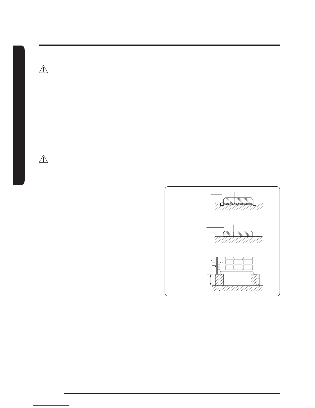
Supporting base construction
Unit: mm
When installing on the ground
Draining pit
200 or more
When installing on the roof
Bottom surface of
the supporting base
must be horizontally
leveled
200 or more
200 or more
Base construction and installation
INSTALLATION
17
English
Product installation
Unit: mm
200 or more
200 or
more
50 or
more
H beam or vibration-isolation frame
Supporting base
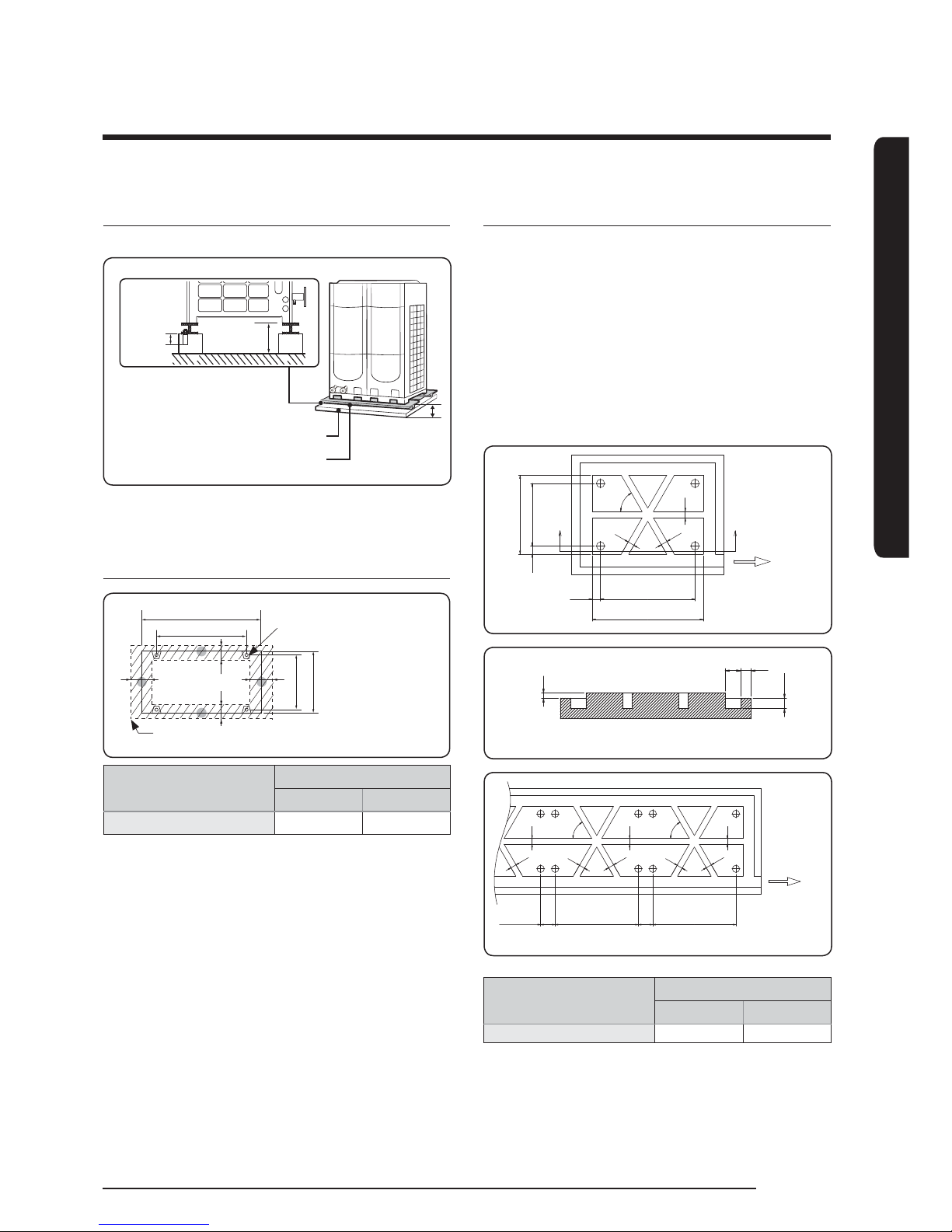
Base mount and anchor bolt
position
A
B
54
761
803
54
Product - vibration-isolation
frame (4 - Ø12)
Supporting base (H beam or vibraition-isolation frame)
Applied model
Net dimension
AB
AG042/056/070
✴✴
1,795 1,655
ŷWhen applying vibration-isolation frame additionally
on supporting base, specication of xed holes with
the base should be referred to specication of the
frame.
Examples of draining work
fUse concrete or steel bar for draining work to
prevent any damage or cracks.
fFor smooth draining of defrost water, make sure to
apply 1/50 slant.
fConstruct a drainage around the product to prevent
the defrost water (from the product) from stagnating,
overowing or freezing near the installation space.
fWhen the product is installed on the roof, check the
strength and waterproof status of the roof.
Unit: mm
960
760
100
80
80
80
60°
100
X
X’
Direction of the
drainage
(1/50 slant)
B
A
50
100
150 100
X-X’ SECTION
80
80
80
80
80
80
80
80
60°
60°
200
BB
200
Direction
of the
drainage
(1/50 slant)
Applied model
Net dimension
AB
AG042/045/070
✴✴
1,855 1,655
INSTALLATION
Base construction and installation
18
English
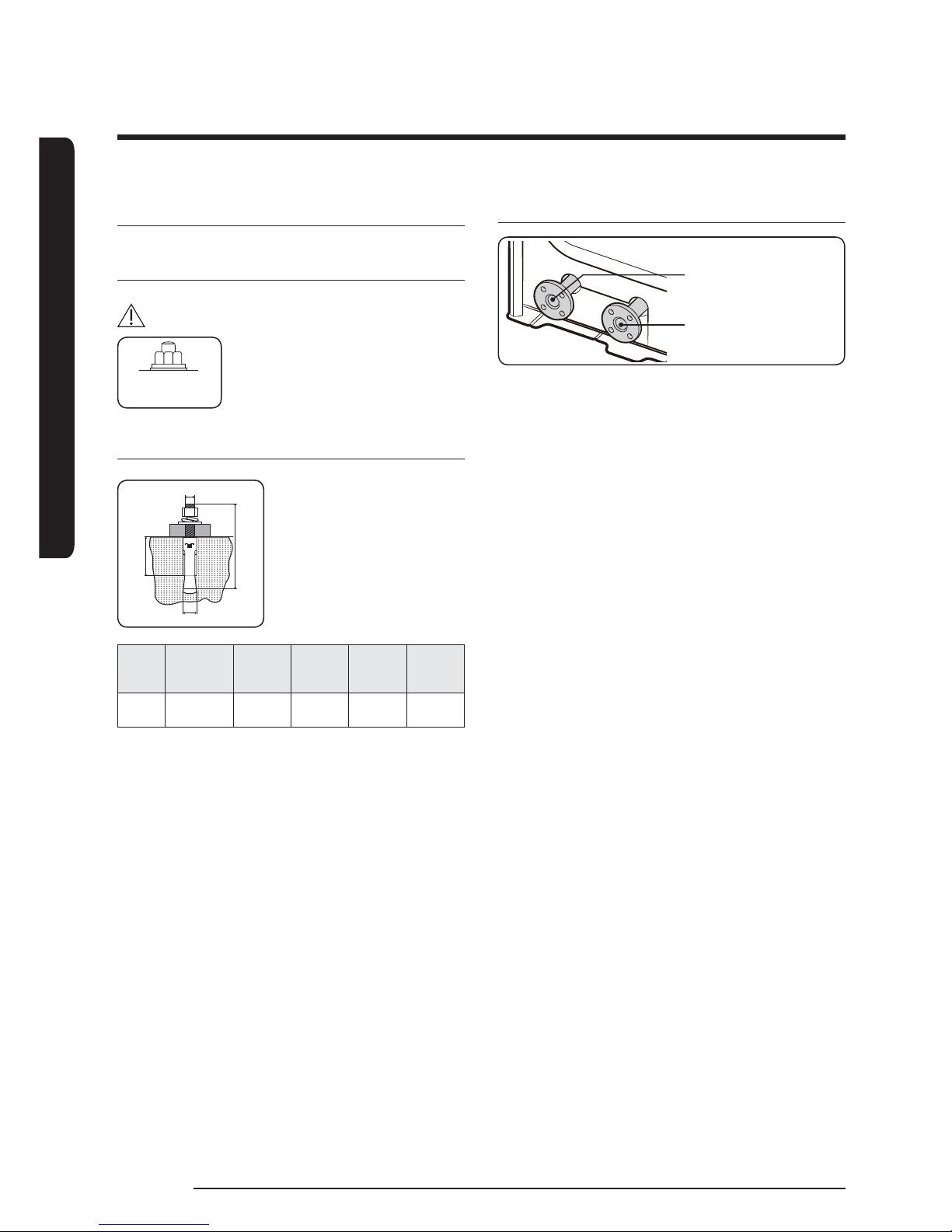
Installation precautions
Connecting the anchor bolt
CAUTION
Plastic (rubber)
washer
ŷTighten the rubber washer to
prevent the bolt connection
part of the DVM CHILLER from
corroding.
Anchor specication
a
b
c
m
ŷUse the anchor bolts and nuts
that is zinc plated or made
of STS material. Regular
anchor bolts or nuts may get
damaged by corrosion.
Size
Diameter of
drill bit (a)
Anchor
length (b)
Sleeve
length (c)
Insertion
depth
Fastening
torque
ø10 14 mm 75 mm 40 mm 50 mm 30 N·m
Connecting the pipe
Water inlet pipe
Water outlet pipe
fIf you install the DVMCHILLER on the rooftop,
check the strength and make sure to waterproof the
rooftop.
fConstruct draining pit around the supporting base
and pay attention to the drainage around the
product. (Condensation or defrost water may form
during product operation.)
fIf there's any possibility of small animals entering
into the product through pipe outlet, block the outlet.
INSTALLATION
19
English
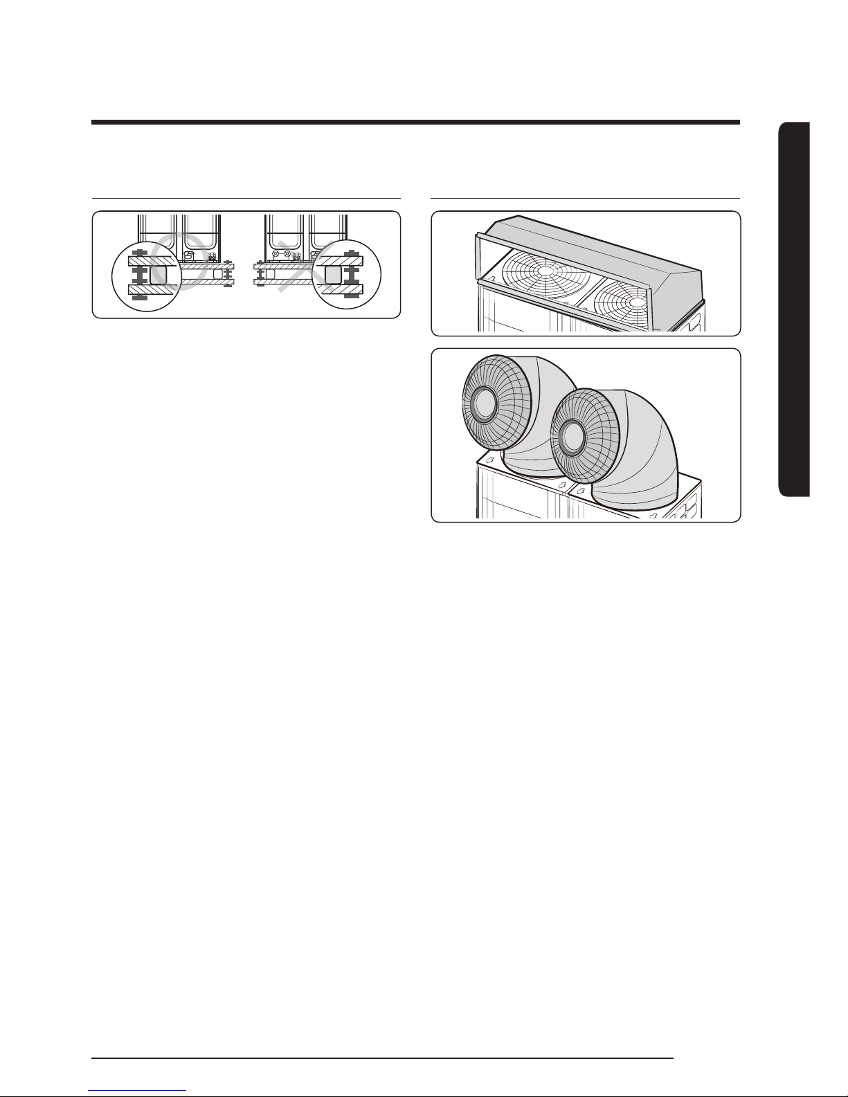
Installing vibraiton-isolation frame
fDuring installation, make sure there is no gap
between the supporting base and the extra structures
such as vibration-isolation frame or H beam.
fSupporting base must be constructed strongly to
support the bottom part of the vibration-isolation
mount.
fAfter installing the vibration-isolation frame, unscrew
the xing part on the top and bottom part of the
frame.
Installing discharge duct
fStatic pressure of the discharge duct should be within
the standard specication (80 kPa) when installing
the duct.
fIf you remove the fan guard to install the discharge
duct, make sure to install a safety net on the duct
outlet.
Foreign substance may enter into the product and
there could be a risk of personal injury.
fWear protection equipment at all times when making
galvanized sheet metal duct, since the worker may
get injured by the sharp parts.
fWhen installing the product under the tree or
near forest, leafs may get into the product and
cause problems on the product. Therefore, install
a discharge duct to prevent foreign substance
inltration.
INSTALLATION
20
English
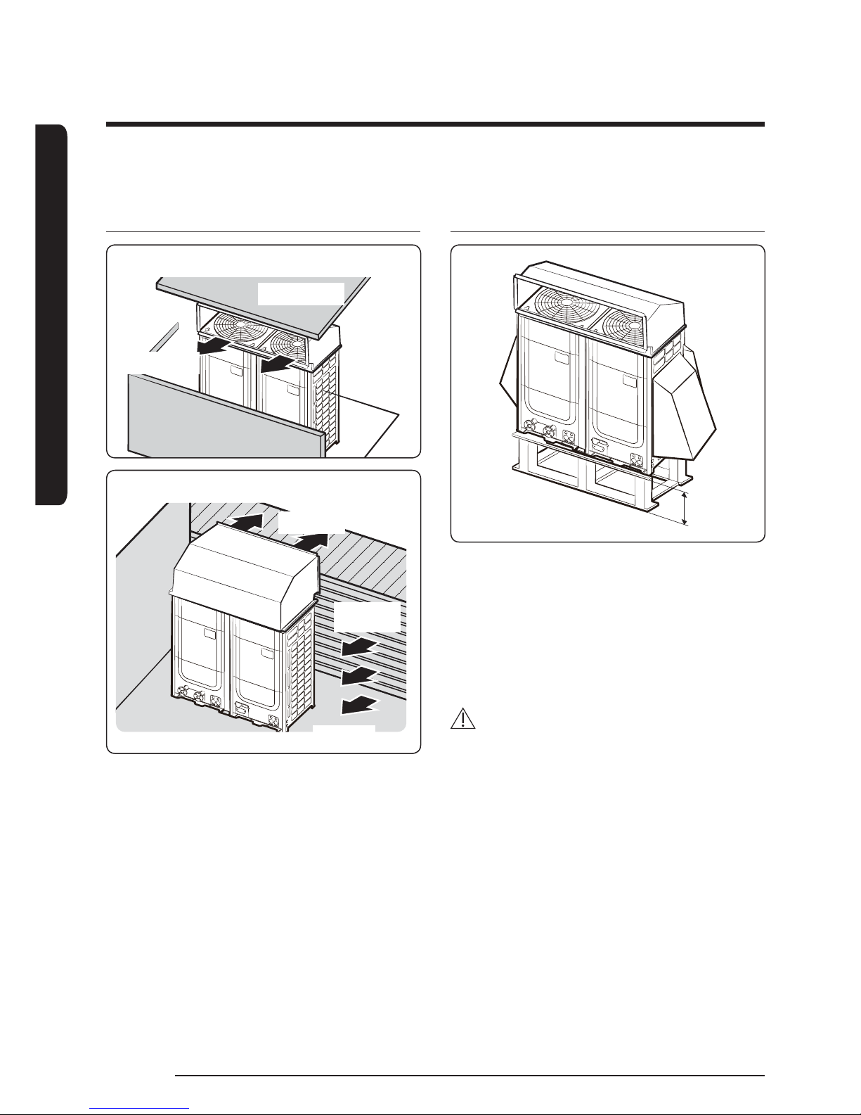
Installing the discharge duct
around the obstacles
Ex.) Balcony
Upper oor
Discharged air
Ex.) Mechanical room
Discharged
air
Grille/
louver
Suction air
fIt is necessary to install a wind/snow prevention
duct (eld supply) to direct exhaust from the fan
horizontally, when it is difcult to provide a minimum
space of 2m between the air outlet and a nearby
obstacle.
Installing the discharge duct in
cold regions
h
fIn cold regions with lots of snowfall, install a snow
prevention duct, as a sufcient countermeasure, to
prevent snow from accumulating on the product.
When the snow prevention duct is not installed
properly, frost may accumulate on the heat exchanger
and heating operation may not work normally.
fAir outlet of the duct should not be directed to the
enclosed space.
CAUTION
Cautions regarding on installing the frame and selecting
the base ground
ŷHeight (h) of the frame and the base ground should
be higher than the "heaviest expected snowfall".
ŷArea of the frame and the supporting base should
not be larger than the area of the product. Snow
may accumulate if the area of the frame or the base
ground is larger.
Installing the wind/snow prevention duct
INSTALLATION
21
English
Installing the discharge duct in
regions with strong wind
fIn windy regions such as near sea shores, protection
wall or wind protection duct must be installed
for normal operation of the product. (Refer to the
illustration of the snow prevention duct, for installing
the wind protection duct.)
fInstall the wind prevention duct with the
consideration of major wind direction. If the direction
of the discharge part is same as major direction
of the wind, it could cause product's performance
decrease.
1795560 560
2300
1695
1150
180
980
1697
2915
593
612
1210
1318
127
871
550765
668
532
2271
1134
965
180
CAUTION
Cautions regarding on installing the frame and selecting
the base ground
ŷThe base ground must be solid and the product
must be xed with anchor bolts.
ŷMake sure to install the product in a place strong
enough to withstand its weight.
If the place cannot withstand the weight of the
product, product may fall and cause personal injury.
ŷWhen installing on a rooftop subject to strong wind,
countermeasures must be taken to prevent the
product from falling down.
ŷUse a frame that is resistant to corrosion.
INSTALLATION
22
English
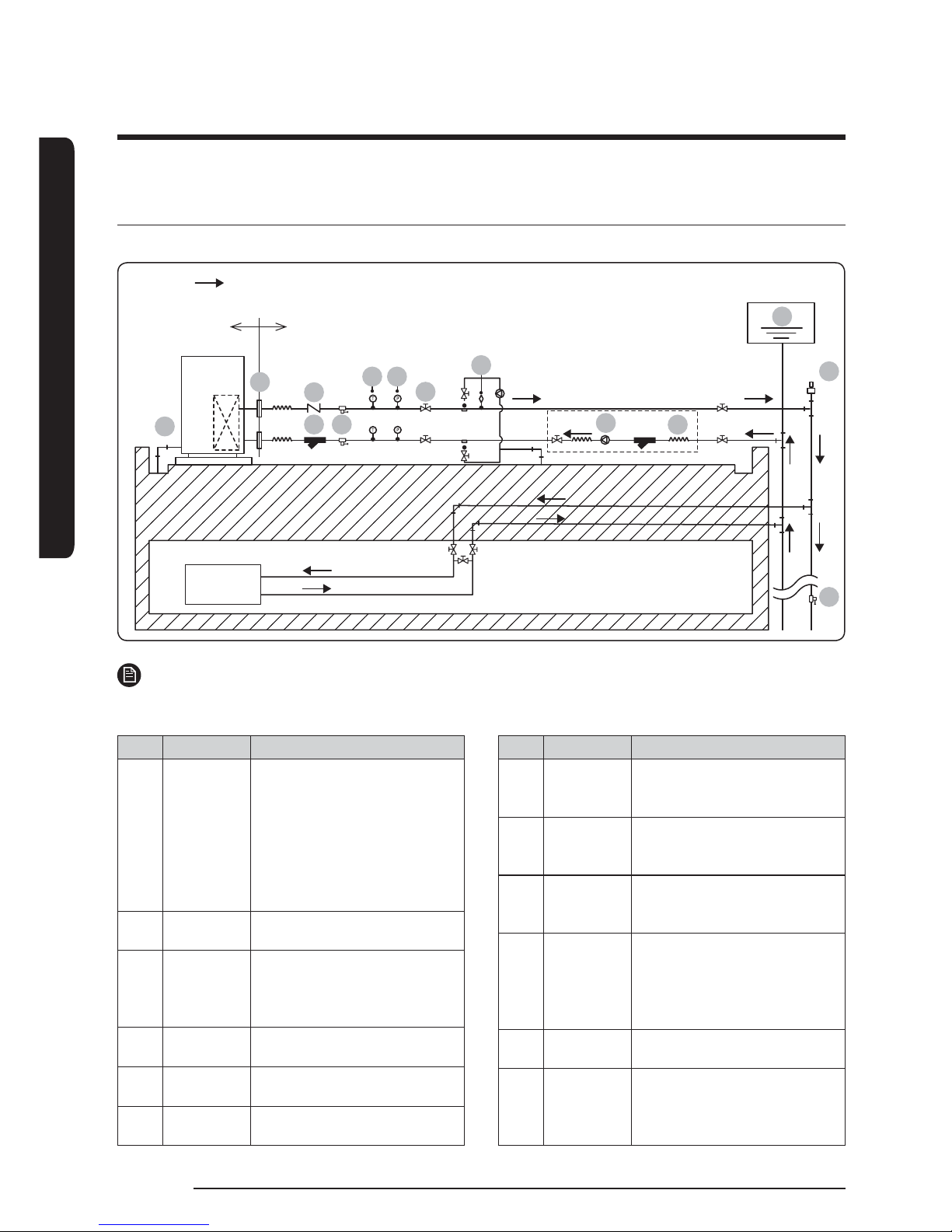
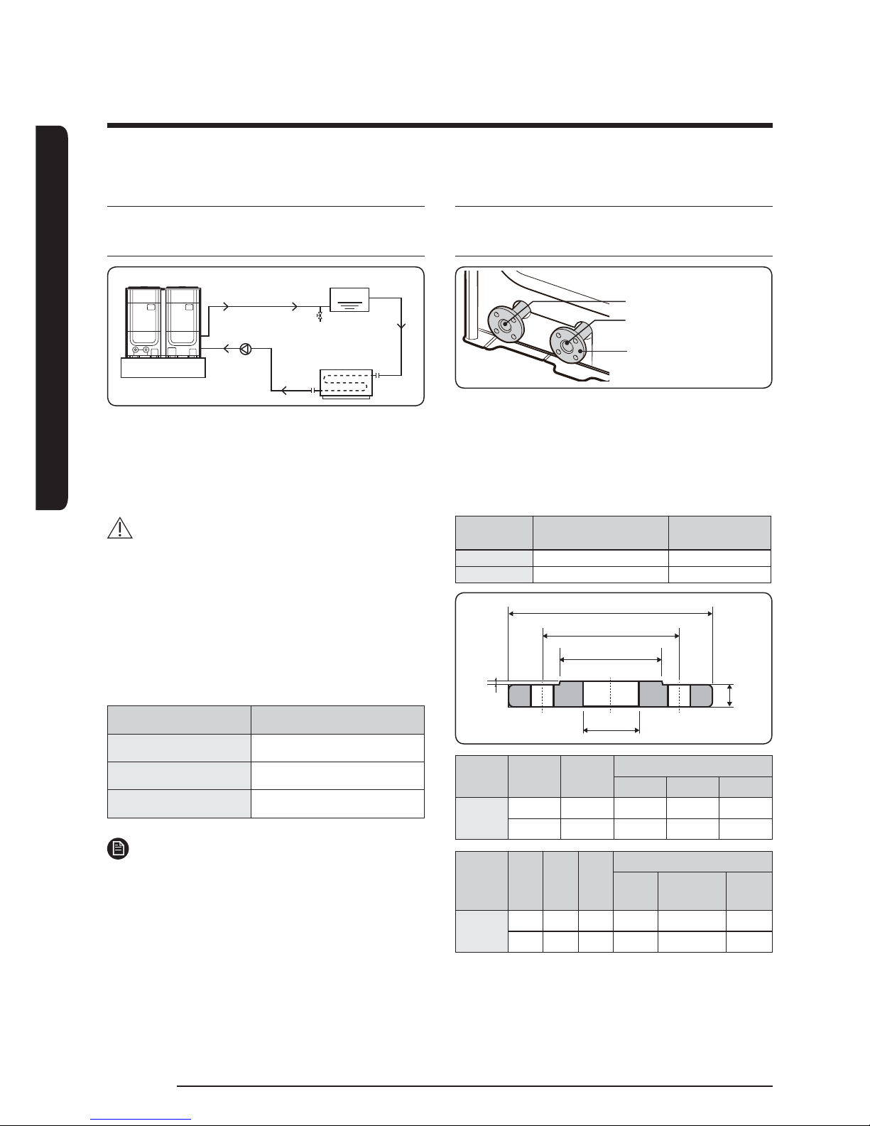
Water pipe diagram
Install the water system according to the diagram.
Direction of water ow
Expansion vessel
Cleaning and ushing pipe
(Install when cleaning)
Load unit
AHU or
Fancoil
DVM CHILLER
Field scope
Water side heat
exchanger
030704
10
11
09
12
08
01
04
0605
02
08
NOTE
ŷThe part shown in the dotted line is an installation example of AG
✴✴✴
KSVA series (non-pump models).
No. Name Remarks
01 Drain plug
Make 1/100 ~ 1/200 for drain
to ow by height difference. To
prevent freezing in winter time,
make slope steep and distance of
level side short as possible. Take
appropriate countermeasures
such as drain heater to prevent
freezing in cold region.
02 Flange
Install ange to allow unit
exchange.
03 Strainer
Install strainer at the nearest
place of the product to prevent
foreign materials ow into water
side heat exchanger. (50Mesh)
04 Drain valve
Install drain valve to drain water
for service.
05
Temperature
gauge
It is recommended for checking
ability and operation.
06
Pressure
gauge
It is recommended for checking
operation status.
No. Name Remarks
07 Valve
Install valves for services such
as owmeter exchange and
cleaning.
08
Air vent
valve
Install air vent valve where
there is a risk of air remaining.
(Auto air valve usable)
09 Check valve
Install check valve to prevent
water owing backward when
pump is stopped.
10 Pump
Install pump which holds amount
for keeping the head loss and
delivering enough water amount
to the product. (Refer to water
ow rate range on page 25.)
11 Flexible joint
It is recommended to prevent
noise and vibration of pump.
12
Expansion
vessel
To absorb the water volume
change caused by temperature
variation, be sure to install the
expansion vessel.
Water pipe installation

INSTALLATION
23
English
WARNING
ŷThe maximum operation water pressure of the
product is 1.0 MPa.
ŷThe water strainer is not included in the product.
You must install 50 Mesh stainless strainer (eld
supply). If the strainer is not installed, it may cause
breakdown of the product.
ŷThe strainer needs periodical maintenance. Work on
pipes considering space for maintenance.
ŷCompanion ange (eld supply) should be made of
SUS304, DIN PN10 standardized product.
Water pipe installation
Installation precautions
fHeat source water with high level of foreign
substances can cause corrosion or creation of water
scale on plate type heat exchanger and pipe, so
select installation place where the heat source water
is qualied according to water maintenance standard
for air conditioning equipment. (Refer to page 68 for
water maintenance standard table.)
fInstall strainer (eld supply) on heat source water
inlet.
fIf sand, dust, corroded particles ow into water
system, heat exchanger may get damaged because of
sedimentation of metallic particles and blocking the
heat exchanger. (Refer to page 11 for specication of
strainer.)
fBe careful not to change inlet/outlet of chilled/
heating water.
fFor normal operation, supply chilled/heating water
regularly to keep operation conditions stable.
fInstall valves at inlet/outlet of water pipes for
services.
fInstall temperature gauge and pressure gauge at
inlet/outlet of water pipes to check operation status.
fInsulate pipes to prevent thermal loss of water pipes
and freezing of pipe surface.
fWhen insulation is not done thoroughly, you will
waste energy caused by thermal loss and may get
property damage during cold seasons when water
pipe freezes. If the product is stopped at night or not
operated for long time during winter time, solution
for water pipe freezing may be necessary. Freezing
may cause product damage, so take appropriate
countermeasures such as pump operation, water
drainage, or heating by heater depending on the
situation.
fInstall exible joints at water pipes to prevent
vibrations.
fSupport water pipes with holders so that too much
weight is not loaded on pipes.
fInstall valves to drain water when the product is not
used for a long time or outdoor temperature is below
freezing point. Use drain valve to drain water left in
plate type heat exchanger and inside the product.
fInstall pipe returning to the pump inside the water
to prevent bubbles when thermal storage or tank is
installed. If dissolved oxygen is increased, corrosion
on water side heat exchanger and pipe can be faster.
INSTALLATION
Water pipe installation
24
English
Installing strainer
fInstall strainer (Field scope: 50 Mesh) that cleaning
is possible at the inlet of DVM CHILLER to prevent
foreign substances such as bolt and stones from
owing into water side heat exchanger.
- If strainer is not installed or the mesh is too
wide, foreign substances may ow into the
system and cause damage by freezing.
fInstall drain valves at inlet/outlet pipes to drain water
from water side heat exchanger for services.
fInstall extra strainer that cleaning is possible near
inlet pipe of the water pump.
Maintaining circulating water amount
fIf the product is operated below minimum amount
of circulating water (more than 50 % of rated ow
rate), plate type heat exchanger may freeze and get
damage. Use the product within circulating water
amount.
fMaintain for water level since it may decrease
by blocked strainer, remaining air, malfunction of
circulating pump.
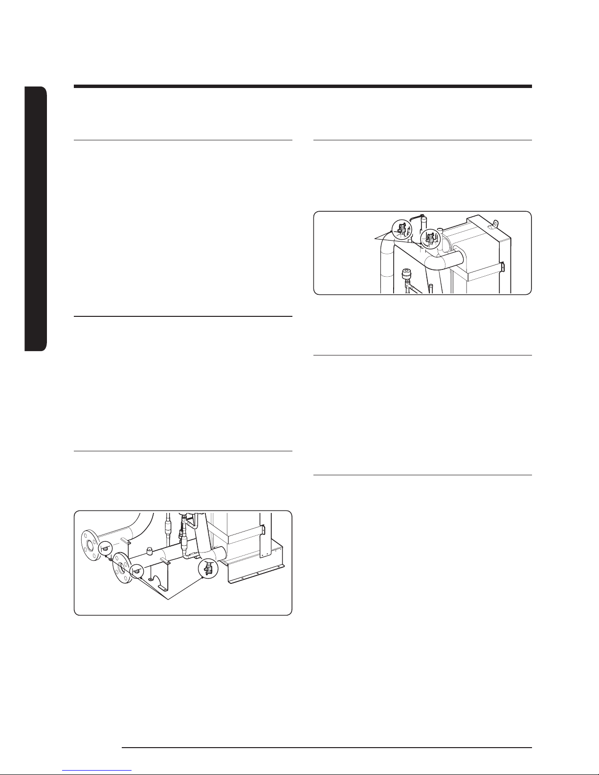
Drainage during winter time
fWhen DVM CHILLER is not operated during winter
time, drain all water by opening drain valves in
CHILLER shown in gure and drain valves in the
pipes.
Drain valve
Air venting
fVent air by opening two air vent valves on inlet and
middle of the pipe of water side heat exchanger.
If air venting is not done properly, it is difcult to
maintain rated ow rate, and pipe corrosion or noise
by remaining oxygen may occur.
Air vent valve
fWhen venting air, be aware to prevent water get in
to the box.
Solution for freeze protection device
When freeze protection device is activated, plate heat
exchanger may freeze. Operate the product after
taking care of the cause. If you operate the product
before the problem has been taken care of, plate type
heat exchanger will be frozen and damaged, causing
refrigerant leakage or water may enter into the
refrigerant cycle.
Solution for pump vibration noise
Install exible joints at inlet/outlet and use vibration
proof rubber on the pump since noise may occur when
pump vibration is transferred to pipes.
INSTALLATION
25
English
Maintaining contamination
Foreign substances included in chilled/heating water by
small particles pass strainers, and they may be stuck or
stacked inside plate type heat exchanger. Some parts of
water pipes inside the plate type heat exchanger, and
the performance may decrease or it may freeze and get
damage. Therefore, clean the plate type heat exchanger
periodically.
Turbidity is a standard for water pollution level, and
standard water pollution set by Corrosion Prevention
Association is under turbidity 4. If the turbidity is high
or foreign substance is ew in too much, clean the
plate type heat exchanger periodically and maintain
the turbidity under 4. If it is over 4, clean the product
in about 1 year period since the rst operation of the
product.
NOTE
ŷRefer to page 68 for water maintenance standard
table.
Solution for water level decrease
When tank or thermal storage is installed open, select
pump which can acquire required water amount
concerning head loss other than pipe resistance.
CAUTION
ŷThe product should be operated for 3 minute after
it is stopped to protect water side heat exchanger
(plate type heat exchanger) from freezing.
NOTE
ŷExpansion vessel is to buffer expanded water and
also to purge air in water pipes. The capacity of
expansion vessel should be 2 ~ 2.5 times larger
than amount of water expansion or 4 ~ 5 % of total
amount of circulating water.
Freeze protection operation
Forced pump operation may be operated periodically
to protect water side heat exchanger (plate type heat
exchanger) from freezing in winter time or night time
when the pump is stopped. Be careful not to be injured.
Water ow rate range
Refer to the table to maintain minimum amount of
circulating water. If circulating amount is not enough,
the product will not only operate in best performance
but also affect the life of the product. Keep the amount
above the minimum level.
Model name
Flow rate range (LPM)
Min. Max.
AG042KSV Series 60 240
AG056KSV Series 80 320
AG070KSV Series 93 400
INSTALLATION
Water pipe installation
26
English
Securing water storage
Minimum water storage
Chilled/
heating
water pump
Buffer tank
Fan coil
fIf the length of water pipe is too short, water storage
within the system becomes lower and ON/OFF
operation of the compressor occurs more often. For
stable operation, maintain certain water storage by
applying header or Buffer tank.
CAUTION
ŷWhen installing tank, inlet pipe of the tank must be
installed under the water level.
fIf total water storage becomes under the minimum
storage, install another tank to retain more water
storage.
- In case of variable ow system, retain certain
amount of water by bypass pipe system.
Model name Minimum water storage (L)
AG042KSV Series 294
AG056KSV Series 392
AG070KSV Series 490
NOTE
ŷTotal water storage in the system = water storage
within the water pipe + water storage in DVM
CHILLER + water storage in AHU (or fan coil)
ŷMinimum capacity of buffer tank = Minimum
water storage - Total water storage in the system
excluding buffer tank
ŷSelect the capacity of buffer tank according to
system installation condition of the eld.
Water amount within the DVM CHILLER: AG042
✴✴✴
,
AG056
✴✴✴
: 12liter / AG070
✴✴✴
: 15.3 liter
Water pipe installation
Connecting water pipe
Chilled/heating water inlet
Chilled/heating water outlet
Flange
fCompanion ange is not supplied. Use eld supplied
one in DIN standardized product.
fWhen connecting the water pipe, use companion
ange and bolt made of SUS304, DIN PN10
standardized product.
fMaintain the tightening torque for ange as the table.
Water pipe
size
Allowable torque for
ange (N·m)
Material of
gasket
40 A
6.8 EPDM
50 A
12.7 EPDM
D
C
G
t
f
d
Size D
t
W.N. Slip-On Blind
DIN PN10
40 150 16 16 16
50 165 18 18 18
Gfd
Bolting
C
Diameter of
holes
Bolt size
DIN PN10
88 3 44.5 110 18 4-M16
102 3 57 125 18 4-M16
INSTALLATION
27
English
Using the pump
NOTE
ŷThe description below applies to AG
✴✴✴
KSVG series
models only.
Startup
CAUTION
ŷDo not start the pump until it has been lled with
liquid.
WARNING
ŷPay attention to the direction of the vent hole,
and make sure that the escaping hot or cold liquid
does not cause injury to persons or damage to the
equipment.
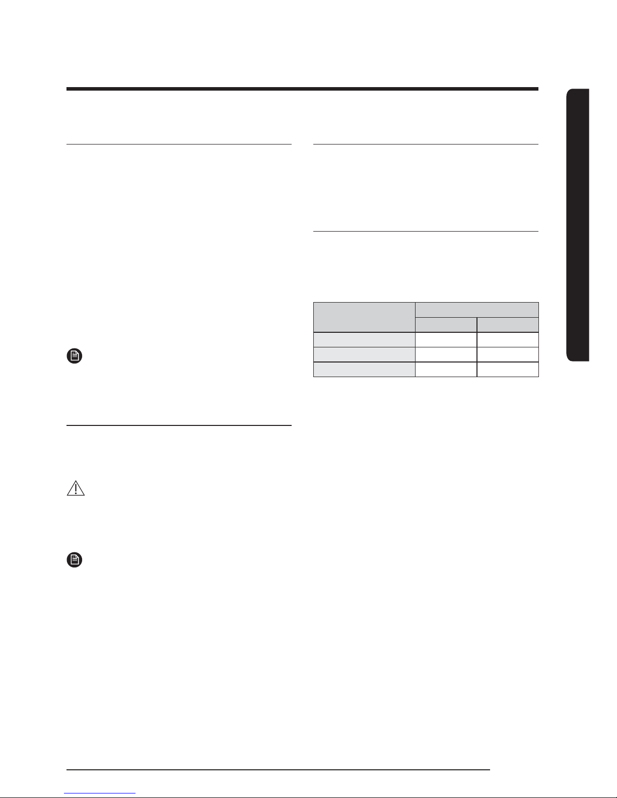
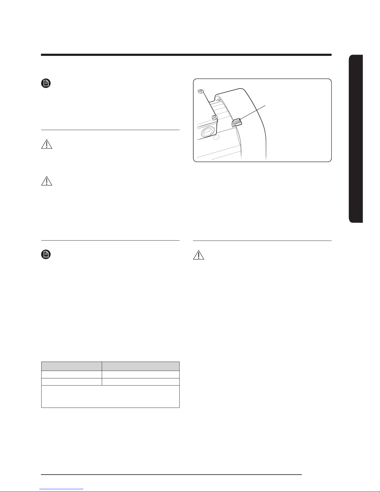
Checking the direction of rotation
NOTE
ŷThe description below applies to three-phase
motors only.
The motor fan cover has an installation indicator. See
g. 1. Based on the motor cooling air, it indicates the
direction of rotation of the motor.
Before the motor is started for the rst time or if
the position of the indicator has been changed, the
indicator function should be checked, for instance by
moving the indicator eld with a nger.
To determine whether the direction of rotation is
correct or wrong, compare the indication with the table
below.
Indicator eld Direction of rotation
Black Correct
White/reecting Wrong*
* To reverse the direction of rotation, switch off
the power supply and interchange any two of the
incoming supply wires.
Indicator eld
Fig. 1 Installation indicator
You can place the indicator in various positions on the
motor, but do not place it between the cooling ns close
to the screws that hold the fan cover.
The correct direction of rotation is also shown by
arrows on the motor fan cover.
Maintenance
WARNING
ŷBefore starting work on the pump, switch off the
power supply. Make sure that the power supply
cannot be accidentally switched on.
ŷMake sure that the escaping water does not cause
injury to persons or damage to the equipment.
The internal pump parts are maintenance-free. You
must keep the motor clean in order to ensure adequate
cooling of the motor. If the pump is installed in dusty
environments, clean and check the pump regularly.
Take the enclosure class of the motor into account when
cleaning.
The motor has maintenance-free, greased-for-life
bearings.
INSTALLATION
Using the pump
28
English
Frost protection
Pumps which are not being used during periods of frost
must be drained to avoid damage.
Remove the lling and drain plugs from the pump.
Do not ret the plugs until the pump is taken into
operation again.
CAUTION
ŷBefore startup after a period of inactivity, the pump
and the suction pipe must be completely lled with
liquid. See Start up (27).
Cleaning
Prior to a long period of inactivity, ush the pump with
clean water to prevent corrosion and deposits in the
pump.
Use acetic acid to remove possible lime deposits from
the pump.
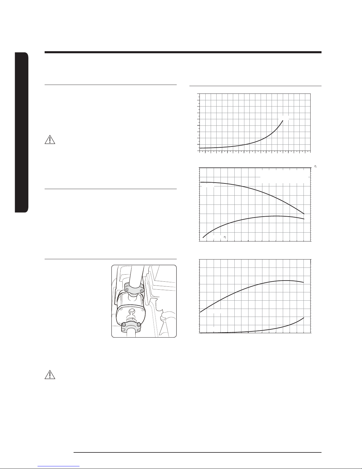
Repairing the pump and connecting the
pipe
We recommend that
you t isolating valves
on either side of the
pump. It is thus not
necessary to drain the
system if the pump
needs service.
The pump must not
be stressed by the
pipework.
Coupling bolt torque: 200 ± 10% kgfcm
The torque must not be exceeded.
WARNING
ŷAfter product inspection, if the compressor is
operated while the refrigerant piping is leaked,
air may enter inside the compressor. It may cause
abnormal high pressure to develop inside the
compressor, leading to product malfunction or an
explosion.
Pump performance chart
NPSH
[m]
0
0 1 2 3 4 5 6 7 8 9 10 11 12 13 14 15 16 17 Q [m³/h]
2
4
6
8
10
12
14
16
50Hz
H
[m]
30
35
25 100
20
15
10
0
5
[%]
120
140
80
60
40
0
20
0 1 2 3 4 5 6 7 8 9 10 11 12 13 14 Q [m³/h]15
efciency,
Head, H
P
[kW]
1.2
1.6
1.4
1.0 25
0.8
0.6
0.4
0
0.2
NPSH
[m]
30
40
35
20
15
10
0
5
0 1 2 3 4 5 6 7 8 9 10 11 12 13 14 Q [m³/h]15
NPSH
Power, P
ŷNPSH = Net Positive Suction Head
ŷNPSH is the requirement to keep enough pressure
on the system to prevent cavitation.
ŷCavitation : ashing the moving uid into a gas
ŷFrequency : 50Hz
Pumped liquid = Water
Liquid temperature = 20°C
Density = 998.2 kg/m³

INSTALLATION
29
English
Fault nding
WARNING
ŷBefore removing the terminal box cover, switch off the power supply. Make sure that the power supply cannot
be accidentally switched on.
ŷThe pumped liquid may be scalding hot and under high pressure. Before any removal or dismantling of the
pump, the system must therefore be drained, or the isolating valves on either side of the pump must be closed.
Fault Cause Remedy
1. The pump does not run. a) Supply power failure. Switch on the switch.
Check cables and cable connections for defects
and loose connections.
b) Motor protection tripped. See 2. a), b), c), d), e).
c) Control-current circuit defective. Repair or replace the control-current circuit.
2. Motor-protective circuit
breaker has tripped (trips
immediately when power
supply is switched on).
a) Contacts of the motor-protective
circuit breaker or magnet coil
defective.
Replace the contacts of the motor-protective
circuit breaker, the magnet coil or the entire
motor-protective circuit breaker.
b) Cable connection is loose or
faulty.
Check cables and cable connections for
defects, and replace the fuses.
c) Motor winding is defective. Repair or replace the motor.
d) The pump is mechanically
blocked.
Switch off the power supply, and clean or
repair the pump.
e) The setting of the motor-
protective circuit breaker is too
low.
Set the motor-protective circuit breaker
according to the rated current of the motor.
See nameplate.
3. The motor-protective circuit
breaker trips occasionally.
a) The setting of the motor-
protective circuit breaker is too
low.
See 2. e).
b) Periodic supply fault. See 2. b).
c) Periodically low voltage. Check cables and cable connections for defects
and loose connections. Check that the power
supply cable of the pump is correctly sized.
4. The motor-protective circuit
breaker has not tripped, but
the pump is inadvertently
out of operation.
a) See 1. a), b), c) and 2. d).
5. The pump performance is
unstable.
a) Pump inlet pressure too low. Check the inlet conditions of the pump.
b) Suction pipe is partly blocked
by impurities.
Remove and clean the suction pipe.
c) Leakage in suction pipe. Remove and repair the suction pipe.
d) Air in suction pipe or pump. Vent the suction pipe or pump. Check the inlet
conditions of the pump.
INSTALLATION
Using the pump
30
English
Fault Cause Remedy
6. The pump runs, but gives
no water.
a) Pump inlet pressure too low. See 5. a).
b) The suction pipe is partly
clogged by impurities.
See 5. b).
c) The foot or non-return valve is
stuck in its closed position.
Remove and clean, repair or replace the valve.
d) Leakage in suction pipe. See 5. c).
e) Air in suction pipe or pump. See 5. d).
7. The pump runs backwards
when switched off.
a) Leakage in suction pipe. See 5. c).
b) Foot or non-return valve
defective.
See 6. c).
c) The foot valve is stuck in
completely or partly open
position.
See 6. c).
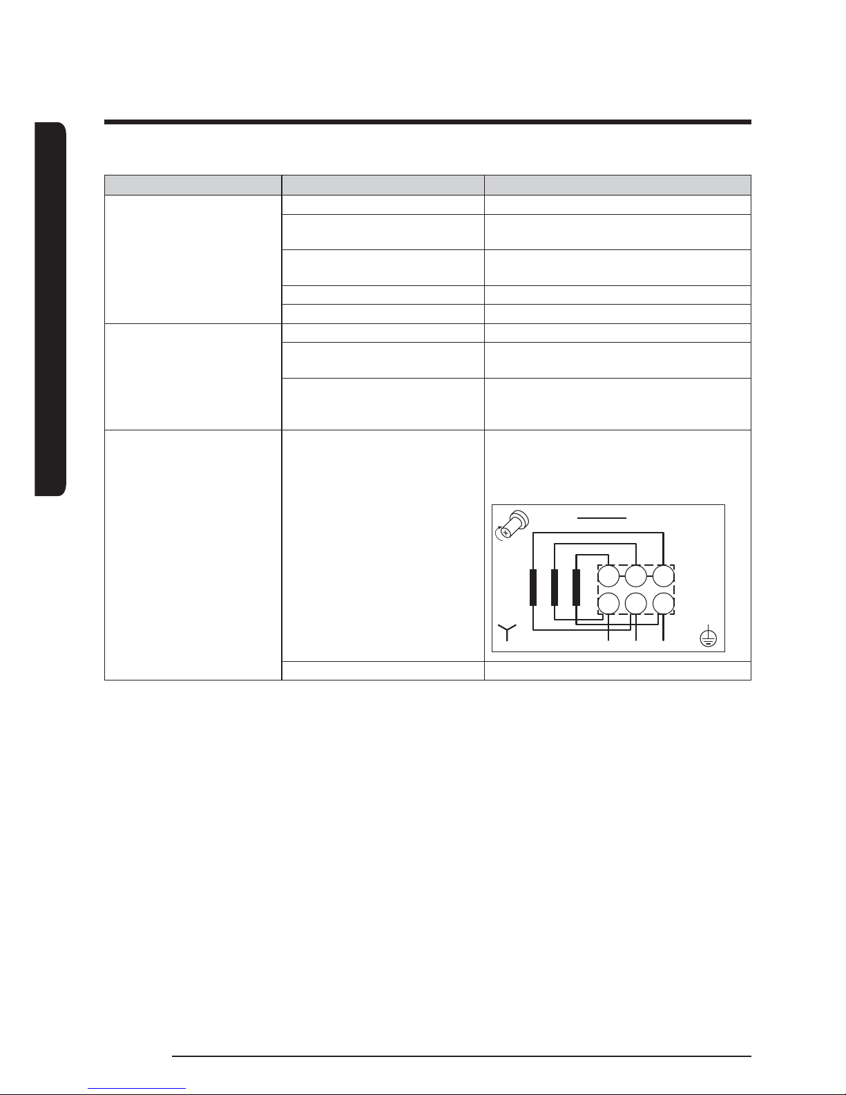
8. The pump runs with
reduced performance.
a) Wrong direction of rotation. Switch off the power supply with the external
circuit breaker, and interchange two phases
in the pump terminal box. See Checking the
direction of rotation on page 27.
W2 U2 V2
U1 V1 W1
HIGH VOLTAGE
DIRECTION OF ROTATION
b) See 5. a), b), c), d).
 Loading...