

Samsung AG042KSVANH, AG056KSVANH, AG070KSVANH, AG056KSVGNH, AG042KSVGNH Service Manual
...
1. Precautions
2. Product Features and Specifications
3. Disassembly and Reassembly
4. Troubleshooting
5. PCB Diagram and Parts List
6. Wiring Diagram
7. Cycle Diagram
8. Key Options
9. Trial Operation
CONTENTSDVM CHILLER
DVM CHILLER
AG042KSVANH/AG056KSVANH/AG070KSVANH
AG042KSVGNH/AG056KSVGNH/AG070KSVGNH
SYSTEM AIR CONDITIONER

DVM CHILLER derived model status
Application division Derived models
Non-built pump AG042KSVANH/EU AG056KSVANH/EU AG070KSVANH/EU
Built pump AG042KSVGNH/EU AG056KSVGNH/EU AG070KSVGNH/EU

1
Contents
1. Precautions ..................................................................................................................................................................................................................................... 1
1-1 Precautions for the Service ............................................................................................................................................................................................ 1
1-2 Precautions for the Static Electricity and PL .......................................................................................................................................................... 1
1-3 Precautions for the Safety .............................................................................................................................................................................................. 1
1-4. Precautions for Handling Refrigerant of the DVM CHILLER ......................................................................................................................... 2
1-5. Precautions for Welding the DVM CHILLER Pipe .............................................................................................................................................. 2
2. Product Features and Specifications .................................................................................................................................................................................. 3
2-1. Product Features .............................................................................................................................................................................................................. 3
2-1-1. Major Advantages of Product .................................................................................................................................................................... 3
2-1-2. Changes in comparison to DVM S............................................................................................................................................................ 6
2-1-3. Structure of product (H/P) ............................................................................................................................................................................ 8
2-2. Product Specifications ................................................................................................................................................................................................... 9
2-2-1. Specifications...................................................................................................................................................................................................... 9
3. Disassembly and Reassembly ................................................................................................................................................................................................ 10
3-1. Necessary Tools ................................................................................................................................................................................................................. 10
3-2. Disassembly and Reassembly ..................................................................................................................................................................................... 11
3-2-1. AG042/056/070KSV666 ............................................................................................................................................................................. 11
3-2. Service work of main parts .......................................................................................................................................................................................... 16
3-3-1. Water Pump ........................................................................................................................................................................................................ 16
3-3-2. Temperature sensor & Pressure sensor in the water pipe side .................................................................................................. 18
3-3-3. Plate type heat exchanger PHE ................................................................................................................................................................. 20
4. Troubleshooting ........................................................................................................................................................................................................................... 29
4-1. Check-up Window Description .................................................................................................................................................................................. 29
4-2. Service Operation ............................................................................................................................................................................................................. 30
4-2-1. Special operation .............................................................................................................................................................................................. 30
4-2-2. DVM Chiller EEPROM code table by models ....................................................................................................................................... 33
4-2-3. Option code by model classification ...................................................................................................................................................... 33
4-2-4. Number Display Method .............................................................................................................................................................................. 34
4-3. Appropriate measures for symptoms..................................................................................................................................................................... 38
4-3-1. Reversed phase / No phase check (Outdoor unit with 3 phase power) ............................................................................... 38
4-3-2. Main PCB has no power phenomenon ................................................................................................................................................. 40
4-3-3. Communication error between hydro and outdoor unit during tracking .......................................................................... 41
4-3-4. Communication error between indoor and outdoor unit after tracking ............................................................................. 43
4-3-5. Internal communication error of the outdoor unit C-Box ............................................................................................................ 44
4-3-6. Internal PCB communication error of the outdoor unit C-Box .................................................................................................. 45
4-3-7. Outdoor temperature sensor error .......................................................................................................................................................... 47
4-3-8. COND OUT temperature sensor error (Open / Short) .................................................................................................................... 48
4-3-9. Outdoor unit COND OUT sensor breakaway error .......................................................................................................................... 49
4-3-10. Compressor discharge or TOP 1/2 temperature sensor error ................................................................................................. 50
4-3-11. Compressor discharge or TOP temperature sensor breakaway error ................................................................................. 51
4-3-12. E269 : Suction temperature sensor breakaway error ................................................................................................................... 52
4-3-13. High pressure sensor error (Open / Short) ........................................................................................................................................ 53
4-3-14. Low pressure sensor error (Open / Short) .......................................................................................................................................... 54
4-3-15. Suction temperature sensor error (Open / Short) .......................................................................................................................... 55
4-3-16. Liquid pipe temperature sensor error (Open / Short) .................................................................................................................. 56
4-3-17. EVI IN temperature sensor error (Open / Short) .............................................................................................................................. 57
4-3-18. EVI OUT temperature sensor error (Open / Short) ......................................................................................................................... 58
4-3-19. Suction-2 temperature sensor error (Open / Short) ..................................................................................................................... 59
4-3-20. Measures of other outdoor unit error .................................................................................................................................................. 60
4-3-21. E407 : COMP DOWN due to high pressure protection control ............................................................................................... 61
4-3-22. E410 : COMP DOWN due to low pressure protection control ................................................................................................. 62
4-3-23. E416: Suspension of starting due to compressor discharge temperature sensor / TOP temperature sensor 63
4-3-24. 3-phase Input Wiring error ........................................................................................................................................................................ 64
4-3-25. E428: : Suspension of starting by abnormal compression ratio .............................................................................................. 65

2
Contents
4-3-26. EVI EEV opening error .................................................................................................................................................................................. 66
4-3-27. Refrigerant leakage error ........................................................................................................................................................................... 67
4-3-28. Prevention of heating operation due to outdoor temperature ............................................................................................. 68
4-3-29. Fan starting error ............................................................................................................................................................................................ 69
4-3-30. Fan lock error ................................................................................................................................................................................................... 71
4-3-31. Momentary blackout error ........................................................................................................................................................................ 72
4-3-32. Outdoor Fan Motor overheating ........................................................................................................................................................... 73
4-3-33. Fan IPM Overheat error ............................................................................................................................................................................... 74
4-3-34. Compressor starting error ......................................................................................................................................................................... 75
4-3-35. Inverter Overcurrent error ......................................................................................................................................................................... 77
4-3-36. Overvoltage / Low voltage error ............................................................................................................................................................ 80
4-3-37. DC Link voltage sensor error .................................................................................................................................................................... 81
4-3-38. Fan Motor Overcurrent error.................................................................................................................................................................... 82
4-3-39. Input / Output Current sensor error ..................................................................................................................................................... 84
4-3-40. Outdoor Fan PCB Overvoltage / Low voltage error ...................................................................................................................... 85
4-3-41. Hall IC (Fan) error ............................................................................................................................................................................................ 86
4-3-42. Inverter overheat error ................................................................................................................................................................................ 87
4-3-43. Option setting error of outdoor unit .................................................................................................................................................... 88
4-3-44. Hydro inlet temperature sensor (Tw1) Short/Open ..................................................................................................................... 89
4-3-45. Hydro outlet temperature sensor (Tw2) Short/Open .................................................................................................................. 90
4-3-46. Frozen damage error ................................................................................................................................................................................... 91
4-3-47. Error when freeze prevention Comp Off ............................................................................................................................................ 92
4-3-48. Hydro outlet temperature sensor Breakaway ................................................................................................................................. 93
4-3-49. Water flow error(Water pressure sensor or Flow switch) ........................................................................................................... 94
4-3-50. Error on pump magnetic switch malfunction ................................................................................................................................. 95
5. PCB Diagram and Parts List ..................................................................................................................................................................................................... 96
5-1. ASSY PCB MAIN-HYDRO .............................................................................................................................................................................................. 96
5-2. ASSY PCB MAIN ................................................................................................................................................................................................................. 97
5-3. ASSY PCB SUB-FAN ........................................................................................................................................................................................................ 102
5-4. ASSY PCB SUB-EMI (PF#8 H power model only) ............................................................................................................................................... 104
5-5. ASSY PCB SUB-EMI (PF #9 H power model only) ............................................................................................................................................. 105
5-6. ASSY PCB MAIN-HUB ..................................................................................................................................................................................................... 107
5-7. ASSY PCB INVERTER ........................................................................................................................................................................................................ 111
5-8. ASSY PCB SUB-COMM ................................................................................................................................................................................................... 115
6. Wiring Diagram ............................................................................................................................................................................................................................. 116
6-1. DVM CHILLER hydro part wiring diagram(AG042/056/070KSVANH/EU) ............................................................................................. 116
DVM CHILLER hydro part wiring diagram(AG042/056/070KSVGNH/EU)............................................................................................. 118
6-2. DVM CHILLER inverter control part wiring diagram(AG042/056KSVANH/EU) .................................................................................. 120
6-3. DVM CHILLER inverter control part wiring diagram(AG070KSVANH/EU) ............................................................................................ 122
6-4. DVM CHILLER inverter control part wiring diagram(AG042/056KSVGNH/EU) .................................................................................. 124
6-5. DVM CHILLER inverter control part wiring diagram(AG070KSVGNH/EU) ............................................................................................ 126
7. Cycle Diagram................................................................................................................................................................................................................................ 128
8. Key options ..................................................................................................................................................................................................................................... 130
8-1. Setting hydro controller option ................................................................................................................................................................................. 130
8-2. How to set hydro controller option ......................................................................................................................................................................... 132
8-3. Setting inverter controller option ............................................................................................................................................................................ 137
9. Trial operation ............................................................................................................................................................................................................................... 142
9-1. Trial operation for each CHILLER unit ..................................................................................................................................................................... 142

1
1. Precautions
1-1 Precautions for the Service
OUse the correct parts when changing the electric parts.
– Please check the labels and notices for the model name, proper voltage, and proper current for the electric parts.
OFully repair the connection for the types of harness when repairing the product after breakdown.
– A faulty connection can cause irregular noise and problems.
OCompletely remove dust or foreign substances on the housing, connection, and inspection parts when performing repairs.
– This can prevent fire hazards for tracking, short, etc.
OCheck whether the parts are properly and securely assembled after performing repairs.
– These parts should be in the same condition as before the repair.
1-2 Precautions for the Static Electricity and PL
OPlease carefully handle the PCB power terminal during repair and measurement when it is turned on since it is vulnerable to
static electricity.
– Please wear insulation gloves before performing PCB repair and measurement.
OCheck if the place of installation is at least 2m away from electronic appliances such as TV, video players, and stereos.
– This can cause irregular noise or degrade the picture quality.
OPlease make sure the customer does not directly repair the product.
– Arbitrary dismantling may result in electric shock or fire.
1-3 Precautions for the Safety
ODo not pull or touch the power plug or the subsidiary power switch with wet hands.
– This may result in electric shock or fire.
ODo not bend the wire too much or position it so that it can be damaged by a heavy object on top.
– This may result in electric shock or fire.
OGround the connection if it is necessary.
– The connection must be grounded if there is any risk of electrical short due to water or moisture.
OFix the product securely to resist natural phenomenon such as earthquake.
– If the product is not properly fixed, it may fall down and cause an accident.
– When installing the unit in a small area, take measure to keep the refrigerant concentration from exceeding allowable safety limits in
case of refrigerant leakage. Consult the dealer for precautionary measure before the installation.
– When refrigerant leaks and exceed dangerous concentration level, it may cause suffocation accidents.

2
1-4. Precautions for Handling Refrigerant of the DVM CHILLER
Environmental Cautions: Air pollution due to gas release
OSafety Cautions
If liquid gas is released, then body parts that come into contact with it may experience frostbite/blister/numbness.
If a large amount of gas is released, then suffocation may occur due to lack of oxygen. If the released gas is heated, then noxious gas may be
produced by combustion.
OContainer Handling Cautions
Do not subject container to physical shock or overheating. (Flowage is possible while moving within the regulated pressure.)
1-5. Precautions for Welding work the DVM CHILLER Pipe
ODangerous or flammable objects around the pipe must be removed before the welding.
OIf the refrigerant is kept inside the product or the pipe, then remove the refrigerant prior to welding.
If the welding is carried out while the refrigerant is kept inside, the welding cannot be properly performed. This will also produce noxious
gas that is a health hazard. This leakage will also explode with the refrigerant and oil due to an increase in the refrigerant pressure, posing a
danger to workers.
OPlease remove the oxide produced inside the pipe during the welding with nitrogen gas.
Using another gas may cause harm to the product or others.
3
• Dual Smart Inverter: SSC + SSC
• BLDC Inverter Motor (14~160 Hz)
• 3
rd
generation Vapor Injection (maximization of low temperature heating performance)
DSI System
Inverter-based
2. Product Features and Specifications
2-1 Product Features
2-1-1 Major Advantages of Product
4
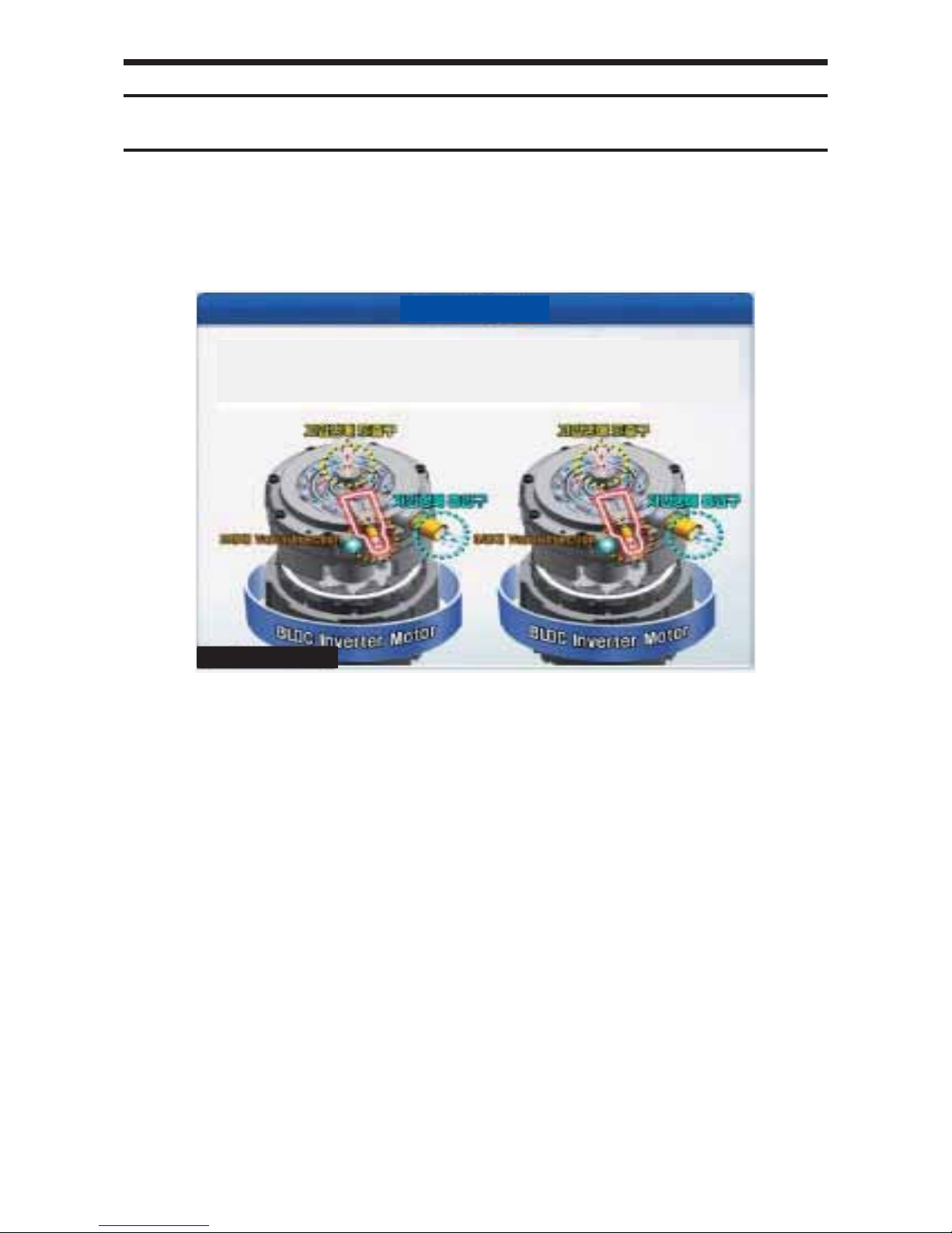
■ Control Logic
1) Simultaneous operation control
Individual capacity control based on Water Out Sensor equipped inside each Unit
Running the capacity control runs all the Units inside the module to control the capacity.
k} tG
㾔⤠
k}
tG
㾔⤠
Start OPERATION
When approaching
the configured temperature
All Units will run simultaneously. Each unit will control the compressor
capacity based on its own discharge
water temperature.
Units that have reached the configured
temperature will Thermo Off.
Capacity control
Capacity control Thermo Off
Capacity control
2) Rotation operation control
Uses the average value of the Water Out Sensor of the Unit whose pump inside the module is in operation.
Running the capacity control will run 1 Unit first. Later, when the relevant Unit is run to maximum capacity, the next Unit in order of
priority will run.
k} tG
㾔⤠
k} tG
㾔⤠
k} tG
㾔⤠
Start OPERATION – Rising capacity
When approaching
the configured temperature
The Unit that has priority of order will be
run first.
The Unit with the previous priority of order
will run at maximum capacity. If its discharge
water temperature does not reach the
configured value, the Unit next in order will
run.
If the Unit last in order of priority is run at
minimum capacity, and if the discharge
water approaches the configured value,
the Unit last in order of priority will
Thermo Off.
Maximum capacity
Maximum capacity
Capacity control
Minimum
capacity
3) Efficiency priority control
Control-based Water Out Temp: Uses the average value of the Water Out Sensor of the Unit whose pump inside the module is in
operation. Precision control while in low load state / Load response speed prioritized when load capacity is increased
k} tG
㾔⤠
k} tG
㾔⤠
Releasing efficient
operation state
Capacity control after releasing
efficient operation state
Efficient operation
capacity
All Units will reach the efficient operation state.
If the discharge water temperature approaches
the configured temperature, the capacity will be
decreased in order of the Unit whose priority is
the lowest.
If the Unit last in order of priority is run at
minimum capacity, and if the discharge water
temperature approaches the configured value,
the last Unit in order of priority will Thermo Off.
k} tG
㾔⤠
k} tG
㾔⤠
k} tG
㾔⤠
k}
t
㾔⤠
Start If there is a stop unit
Entering into efficient
operation state
The Unit whose order of operation
priority is highest will run first.
The Unit with the previous priority of order
will run in the efficient operation state. If its
discharge water temperature does not reach
the configured value, the Unit next in order
will run.
If all Units reach the efficient operation
state, each Unit will run in a capacity
between the efficient operation state
and maximum capacity operation.
Capacity
control
Capacity control Capacity control
Efficient operation
capacity
Capacity control
range
Efficient operation
capacity
5
Feature (cont.)
■ Inverter circuit refrigerant cooling technology
▶
Applied high eciency refrigerant cooling circuit. Secured stable Inverter PCB cooling performance.
- Air cooling method : When natural convection / electric heat performance is low and is high load, eciency is fallen.
- Refrigerant cooling system : Forced circulation / electric heat performance is high and control of (thermal conductivity is
10 times higher than air) load is available.
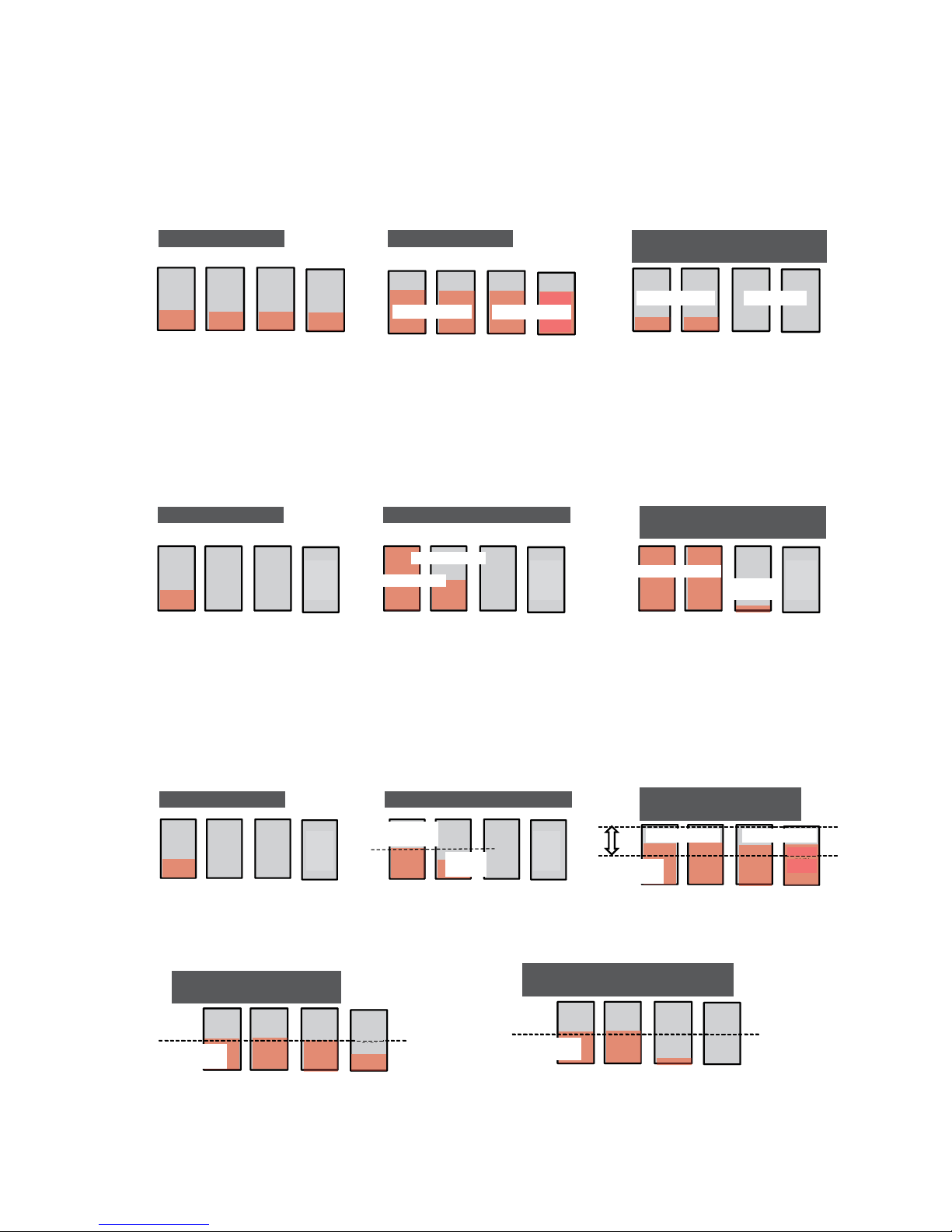
■ Obtained cooling and heating performance by high effectiveness applying plate type heat exchanger
Refrigerant cooling system :
It is cooling technology of inverter circuit that use
refrigerating cycle technology.
Cooling inverter circuit
Efficient operation
capacity
- Manufacture hot/cool water using plate type heat exchanger
- Freeze protection control specication(application for shrinkage temperature/pressure)
- Air purge, Drain valve, In/out ange
Plate type heat exchanger
Air vent valve
Drain valve
Water inlet flange
Water inlet pressure sensor
Water inlet temperature sensor
Water middle coupler
Water outlet pressure sensor
Water outlet temperature sensor
Water outlet flange
※ Pump is applied to pump built-in model only.
6
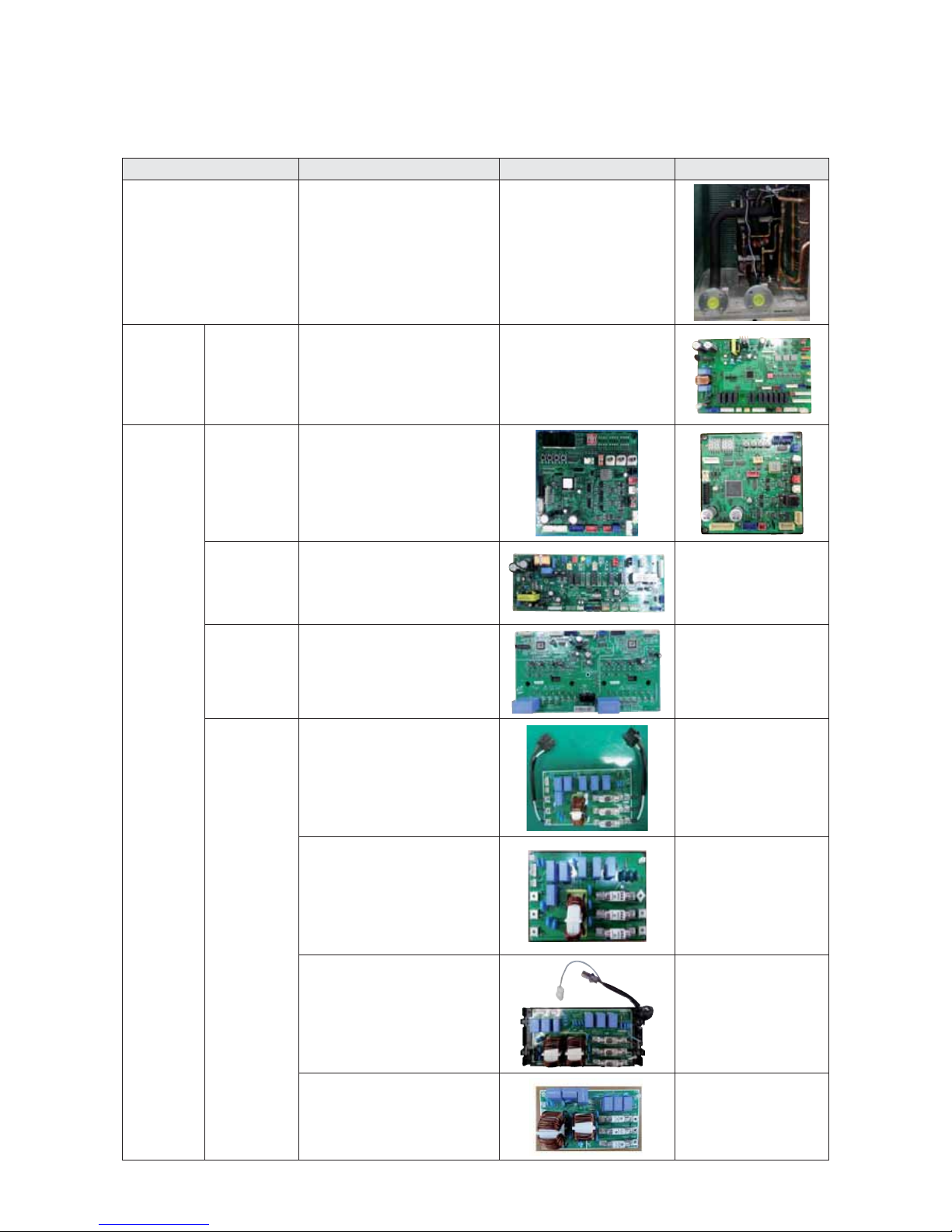
2-1-2. Changes in comparison to DVM S
Changed part Changed item and feature Basic Revision
Hydro
- Producing hot water & cold water
by using plate type heat exchanger.
- Control specification for freeze
prevention(the application of the
water temperature/the pressure
sensor).
- Air purge, Drain valve, Inlet/Outlet
flange.
-
Control Box
(Hydro)
Hydro PCB
New Hydro PCB.
- Hot&Cold water load and
protection control load of Freeze
protection.
- Module controller, External control
contact, Supply of Laod/Sensor.
-
Control Box
(Inverter)
Main PCB
Change Main PCB.
- Separation of Load/Control
Deleting of option resistance by
model.(standardization)
- Need of option download at the
time of the PCB replacement.
Hub PCB
New Hub PCB.
- Separation of Load/Control.
- Improvement of the fixed form of
Load/Sensor wire.
←
FAN PCB
FAN Controller using 3-phase power.
- Prevention of phase imbalance.
- Protection of IPM temperature.
←
EMI PCB
EMI PCB for 3-phase 3-wire power.
- Fuse mounting
- PF No. 8
←
EMI PCB for 3-phase 3-wire power.
- Fuse mounting
- PF No. 9
←
EMI PCB for 3-phase 4-wire power.
- Fuse mounting
- PF No. 8
←
EMI PCB for 3-phase 4-wire power.
- Fuse mounting
- PF No. 9
←
7
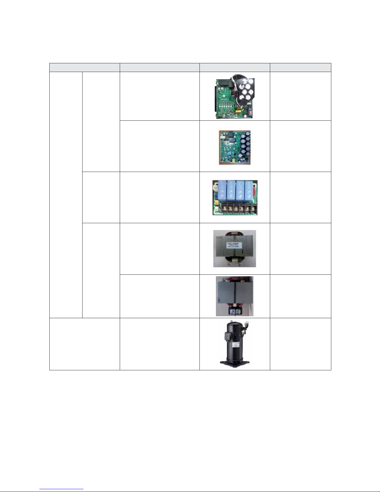
Changes in comparison to DVM S (cont.)
Changed part Changed item and feature Basic Revision
Control Box
(Inverter)
InverterPCB
(Compressor
control
PCB)
PF No. 8 Inverter controller.
←
PF No. 9 Inverter controller.
←
Communication
terminal block
Communication terminal block
mounted on the PCB.
←
REACTOR
Small capacity.
- PF No. 8
←
Large capacity.
- PF No. 9
←
Compressor
70cc high-capacity compressor
application.
←
8
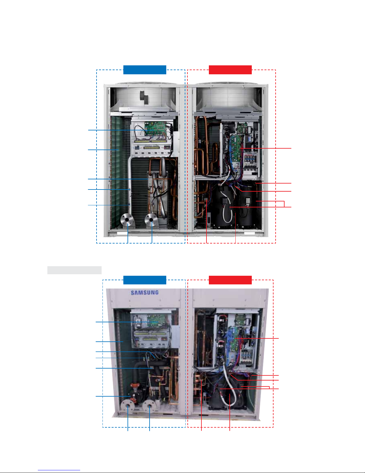
2-1-3. Structure of product (H/P)
Hydro control Inverter control
Control Box
(Hydro Side)
Control Box
(Inverter)
Receiver
Accumulator
Compressor
Oil separatorSub-cooler
Water outletWater inlet
Air side Heat Exchanger
Water Side Heat Exchanger
Water Temp. sensor
Water Pressure sensor
Water outletWater inlet
Control Box
(Hydro Side)
Air side Heat Exchanger
Water Temp. sensor
Water Pressure sensor
Water Side Heat Exchanger
Water Pump
Control Box
(Inverter)
Receiver
Accumulator
Compressor
Oil separator
Sub-cooler
Hydro control Inverter control
Pump built in model only
9
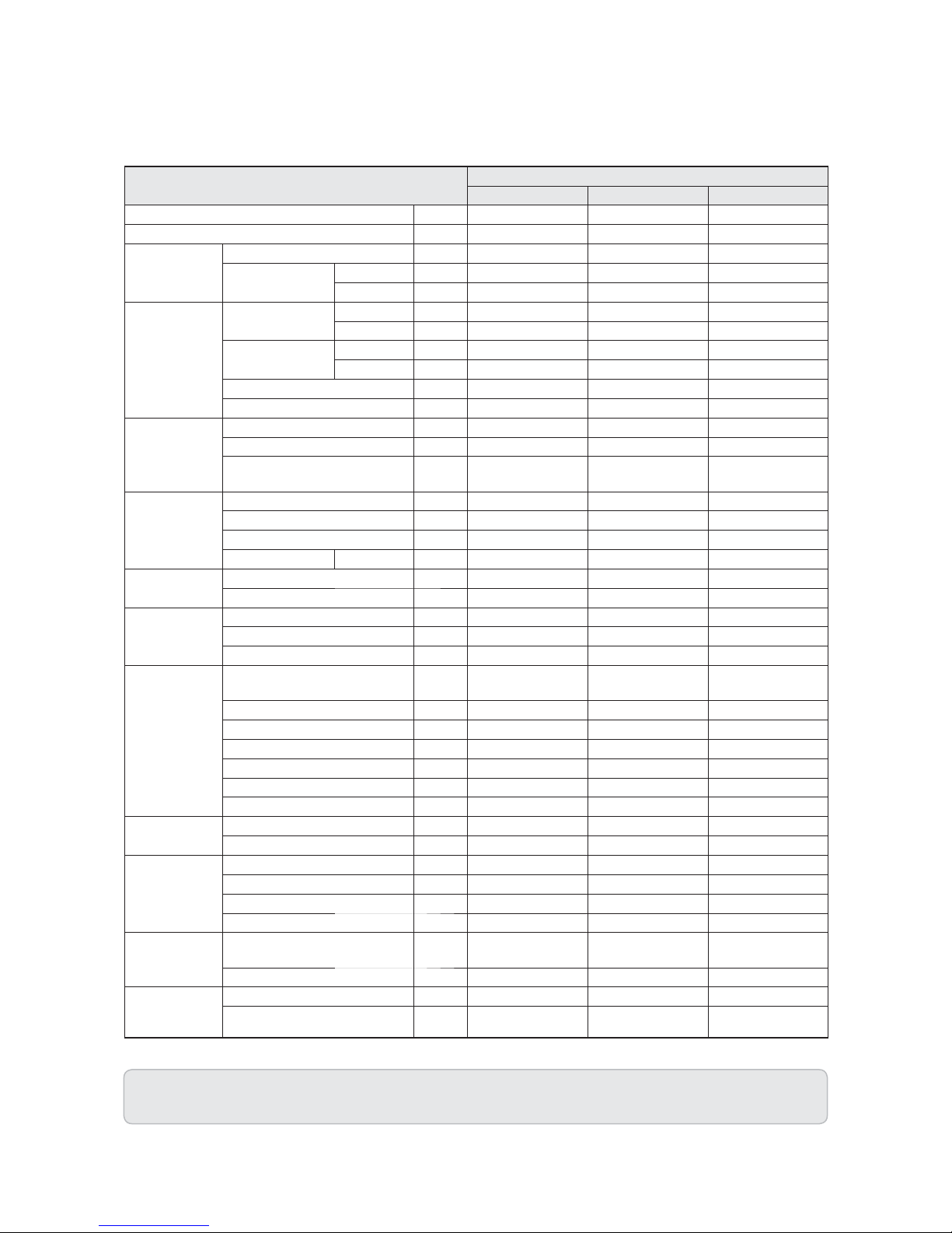
2-2. Product Specifications
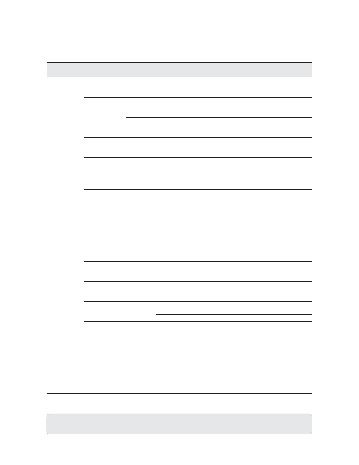
2-2-1. Specifications
1. Cooling capacity Rated by: inlet and outlet water temperature 12/7 ° C, Outdoor side 35 ° C DB, 24 ° C WB.
2. Heating capacity Rated by: mouth and hot water outlet temperature 40/45 ° C, Outdoor side 7 ° C DB, 6 ° C WB.
MODEL
AG042KSVANH/EU AG056KSVANH/EU AG070KSVANH/EU
Mode - HEAT PUMP HEAT PUMP HEAT PUMP
Power Supply Φ,#,V,Hz 3,4,380-415,50/60 3,4,380-415,50/60 3,4,380-415,50/60
Performance
HP HP 15 20 25
Capacity
(Nominal)
Cooling kW 42.0 56.0 65.0
Heating kW 42.0 56.0 69.5
Power
Power Input
Cooling kW 12.35 18.67 26.00
Heating kW 11.83 17.5 24.39
Current Input
Cooling A 19.6 29.6 41.20
Heating A 18.8 27.8 38.70
MCA A 32 46 58
MFA (MOP) A 40 60 75
COP
Nominal Cooling W/W 3.40 3 2.50
Nominal Heating W/W 3.55 3.2 2.85
ESEER(Euro type),
IPLV(American type)
W/W 5.7 5.4 5.0
Compressor
Type - Scroll Inverter Scroll Inverter Scroll Inverter
Output kW × n 6.76x2 6.76x2 6.76x2
Model Name - DS-GB070FAVA DS-GB070FAVA DS-GB070FAVA
Oil Type - PVE PVE PVE
Refrigerant
Type - R410A R410A R410A
Factory Charging kg 18 18 18
Fan
Type - Propeller Propeller Propeller
Output x n W 630 x 2 630 x 2 630 x 2
Air Flow Rate CMM 364 (182 x 2) 364 (182 x 2) 392 (196 x 2)
Water Side Heat
Exchanger
Type -
Plate type heat
exchanger
Plate type heat
exchanger
Plate type heat
exchanger
Water Flow (Cooling/Heating) LPM 120 160 186/200
Pressure Drop kPa 60 100 120
Max Operationg Pressure MPa 1.0 1.0 1.0
Connection Type - FLANGE FLANGE FLANGE
Pipe(Inlet/Outlet) A 40 40 50
Q'Ty EA 2 2 2
Field
Wiring
Power Source Wire mm2 6(H07RN) 10(H07RN) 16(H07RN)
Transmission Cable mm2 VCTF 0.75~1.5(2P) VCTF 0.75~1.5(2P) VCTF 0.75~1.5(2P)
External
Dimension
Net Weight kg 446 446 465
Shipping Weight kg 468 468 487
Net Dimensions (WxHxD) mm 1,795x1,695x765 1,795x1,695x765 1,795x1,695x765
Shipping Dimensions (WxHxD) mm 1,900x1,887x919 1,900x1,887x919 1,900x1,887x919
Operating
Water Temp.
Range
Cooling
&
5 ~ 25
(Brine : -10~25)
5 ~ 25
(Brine : -10~25)
5 ~ 25
(Brine : -10~25)
Heating
°C
25 ~ 55 25 ~ 55 25 ~ 55
Operating
Amb. Temp.
Range
Cooling
°C
-15 ~ 48 -15 ~ 48 -15 ~ 48
Heating
°C
-25 ~ 43 -25 ~ 43 -25 ~ 43
10
Specifications (cont.)
1. Cooling capacity Rated by: inlet and outlet water temperature 12/7 ° C, Outdoor side 35 ° C DB, 24 ° C WB.
2. Heating capacity Rated by: mouth and hot water outlet temperature 40/45 ° C, Outdoor side 7 ° C DB, 6 ° C WB.
MODEL
AG042KSVGNH/EU AG056KSVGNH/EU AG070KSVGNH/EU
Mode - HEAT PUMP HEAT PUMP HEAT PUMP
Power Supply Φ,#,V,Hz 3,4,380-415,50/60
Performance
HP HP 15 20 25
Capacity
(Nominal)
Cooling kW 42.0 56.0 65.0
Heating kW 42.0 56.0 69.5
Power
Power Input
Cooling kW 13.59 * 20.14 * 28.26 *
Heating kW 12.77 * 18.48 * 25.84 *
Current Input
Cooling A 24.2 34.2 45.8
Heating A 23.4 32.4 43.3
MCA A 36.55 50.55 62.55
MFA (MOP) A 40 60 75
COP
Nominal Cooling W/W 3.09 2.78 2.30
Nominal Heating W/W 3.29 3.03 2.69
ESEER(Euro type),
IPLV(American type)
W/W 4.75 4.50 4.10
Compressor
Type - Scroll Inverter Scroll Inverter Scroll Inverter
Output kW × n 6.76*2 6.76*2 6.76*2
Model Name - DS-GB070FAVA DS-GB070FAVA DS-GB070FAVA
Oil Type - PVE PVE PVE
Refrigerant
Type - R410A R410A R410A
Factory Charging kg 18 18 18
Fan
Type - Propeller Propeller Propeller
Output x n W 630*2 630*2 630*2
Air Flow Rate CMM 364(182*2) 364(182*2) 392(196*2)
Water Side Heat
Exchanger
Type -
Plate type heat
exchanger
Plate type heat
exchanger
Plate type heat
exchanger
Water Flow (Cooling/Heating) LPM 120 160 186/200
Pressure Drop kPa 60 100 120
Max Operationg Pressure MPa 1.0 1.0 1.0
Connection Type - Flange Flange Flange
Pipe(Inlet/Outlet) A 40 40 50
Q'Ty EA 2 2 2
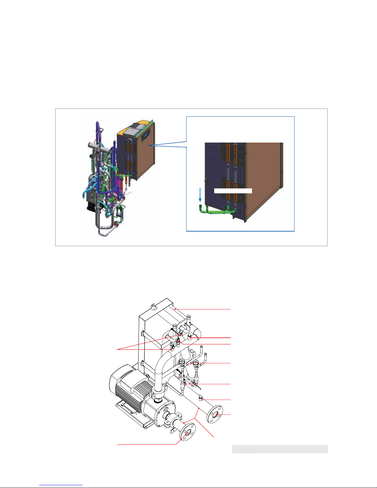
Pump
Type -
End-Suction End-Suction End-Suction
Input x n kW
1.68 1.68 1.68
Output x n kW
1.45 1.45 1.45
Normal Water Flow rate
LPM
120/120 160/160 186/200
l/s
2.0 2.7 3.1/3.3
External Static Pressure (Max.)
mAq
22.4 15.3 10.2
kPa
220 150 100
Field
Wiring
Power Source Wire mm2 6(H07RN) 10(H07RN) 16(H07RN)
Transmission Cable mm2 VCTF0.75~1.5(2P) VCTF0.75~1.5(2P) VCTF0.75~1.5(2P)
External
Dimension
Net Weight kg 472 472 493
Shipping Weight kg 494 494 515
Net Dimensions (WxHxD) mm 1795*1695*765 1795*1695*765 1795*1695*765
Shipping Dimensions (WxHxD) mm 1900*1887*919 1900*1887*919 1900*1887*919
Operating
Water Temp.
Range
Cooling
&
5 ~ 25
(Brine : -10~25)
5 ~ 25
(Brine : -10~25)
5 ~ 25
(Brine : -10~25)
Heating
&
25 ~ 55 25 ~ 55 25 ~ 55
Operating
Amb. Temp.
Range
Cooling
&
-15 ~ 48 -15 ~ 48 -15 ~ 48
Heating
&
-25 ~ 43 -25 ~ 43 -25 ~ 43
* : Includes pump input based on EN14511.
11
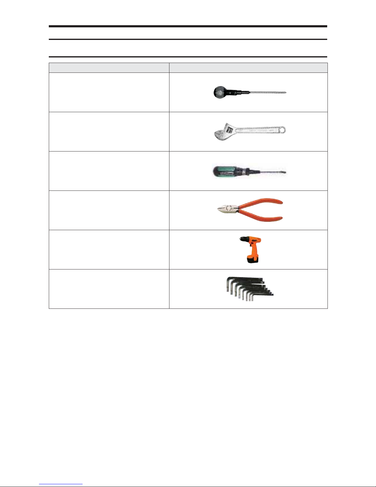
3-1 Necessary Tools
3. Disassembly and Reassembly
Item Remark
+SCREW DRIVER
MONKEY SPANNER
-SCREW DRIVER
NIPPER
ELECTRIC MOTION DRIVER
L-WRENCH
12
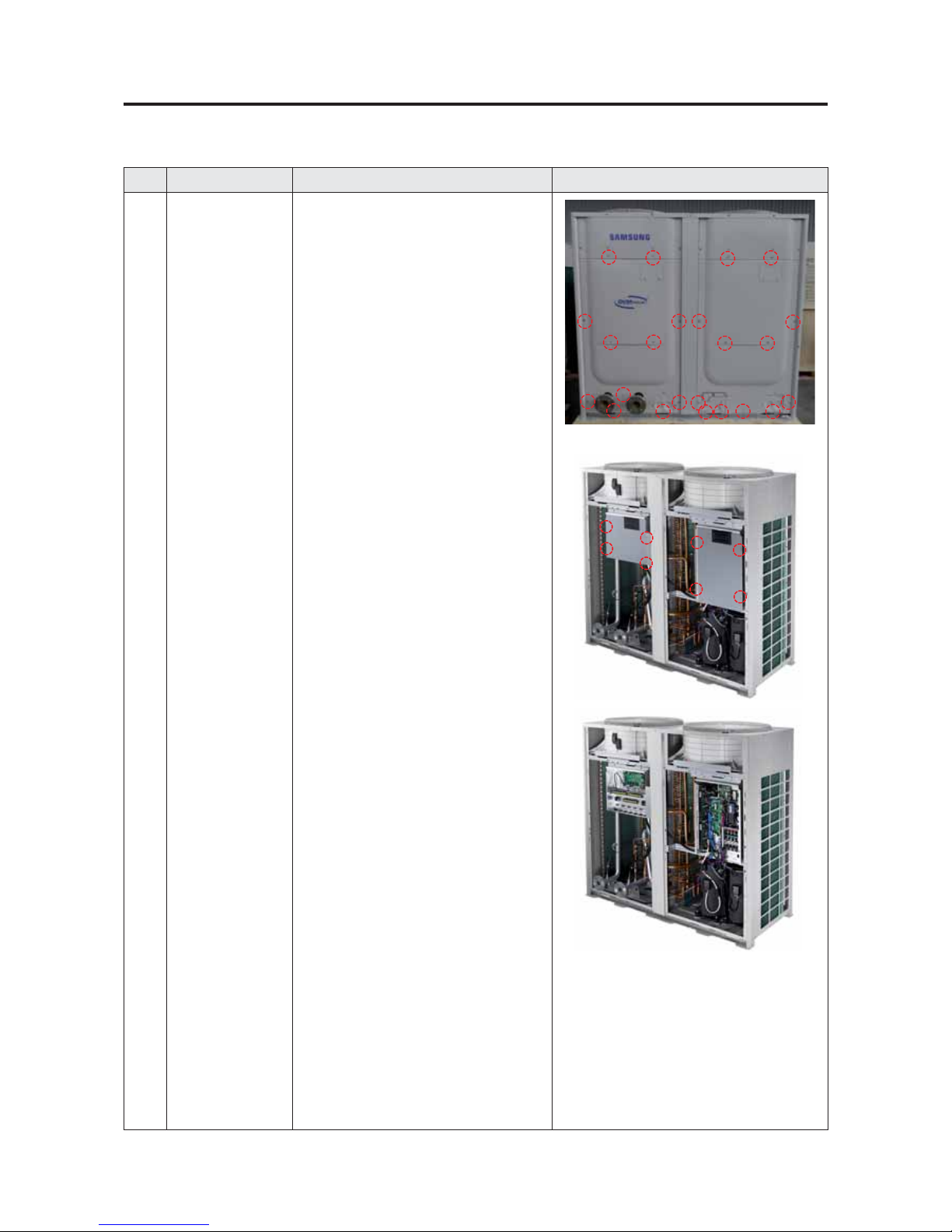
No. Parts Procedure Remark
1 Electrical
equipment parts
1) Remove 24 screws from the Cabinet.
(Use + Screw Driver)
2)
Remove the 8 screws and then separate the left
side Cover Control Box of Hydro part and right
side Cover Control Box of Inverter part. (Use +
Screw Driver)
3)
Remove the Power, Compressor, Valve, Motor,
Sensor connector of Assy PCB.
3-2 Disassembly and Reassembly
3-2-1. AG042/056/070KSV666
13
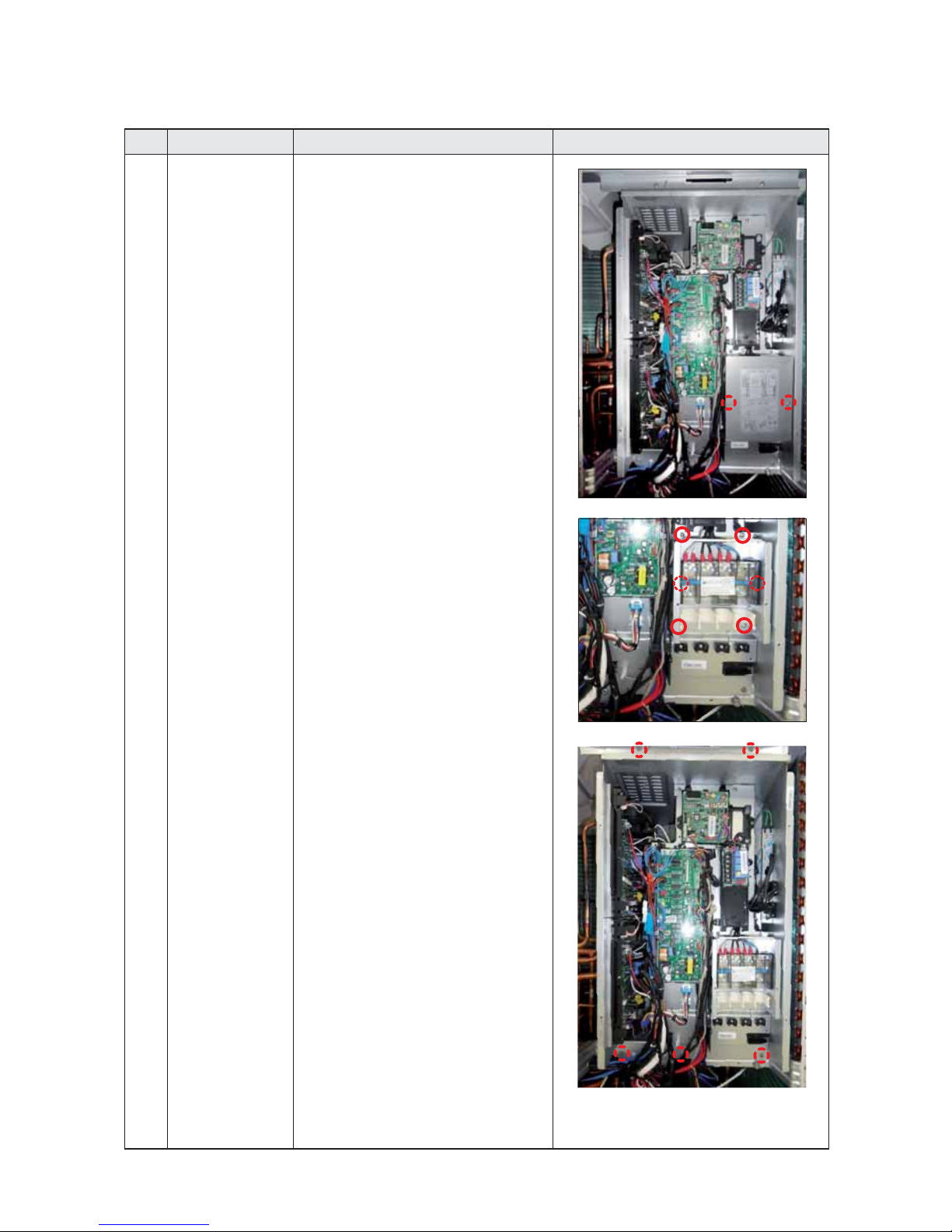
No. Parts Procedure Remark
4) When replacing the Power Terminal Block and
Communication Terminal Block, remove the 2
screws which is fixed to Terminal Block Cover.
5) Remove the 4 screws which is fixed to Cabinet
for Terminal Block protection and then remove
the 2 screws from the Terminal Block.
6) Remove the 5 screws from the front part..

14
No. Parts Procedure Remark
7) Remove the 12 screws from the outside of
side refrigerant cooling part.
Do not separate Heat Sink pulling Assy Piping
Cooling piping compulsorily.
(It can be a cause of parts damage)
8) Remove the 2 screws from the inside of side
refrigerant cooling part.
15
No. Parts Procedure Remark
3 Hydro part Control Box 9) Remove the 4 screws from the front part.
4 Hydro part 10) Remove the 4 screws which is fixed to Bracket
Tube.
11) Remove the 4 screws which is fixed to
Bracket Hydro part.
12) Remove the 2 screws securing the coupling
points. Loosen BRACKET PHE SCREW where
to hold the heat exchanger.
No code SPEC Q'ty
1 6003-001053 M6 2
2 6009-001369 M4 4
3 General NUT M8 2
2
3
2
1
5 Pump part
(Pump built-in model
AG042/056/070
KSVGNH)
13) Separates the pipe connected pump by
separating 4 coupling fixed screws.
14) Separates 3 bracket fixed screws fixed to
base.
No Code SPEC Q' ty
1
GENERAL NUT M8 4
2 6003-001053 M6 3
1
2
2
2
1
1
1

16
3-3 Service work of main parts
3-3-1. Water Pump3-3-1. Water Pump (Pump built in model only)
1) Power off before starting on work.
2) Close the valve connected to inlet/outlet of main water pipe.
3) Drain all water of water pipe connected to DVM CHILLER.
4) Unscrews the screw of inlet/outlet water pipe flange connected to DVM CHILLER.
5) Unscrews the fixed screw of CABINET FRONT.
6) Separates wire of cycle parts connected to ASSY PHE from C-BOX.
7) Separate 2 bolts of coupling connected to ASSY PUMP.
8) Unscrew 3 fixed screw of bracket fixed to Base.
9) Unscrews a fixed screw fixing water pipe IN in front.
10) Let down the coupling Rubber and pull out outwards Pump ASSY by
raising slightly a back of Pump Bracket parts.
11) Separate 2 bolts of pump inlet water pipe by using spanner.
12) Separate 4 fixed nut of pump by using spanner.
17
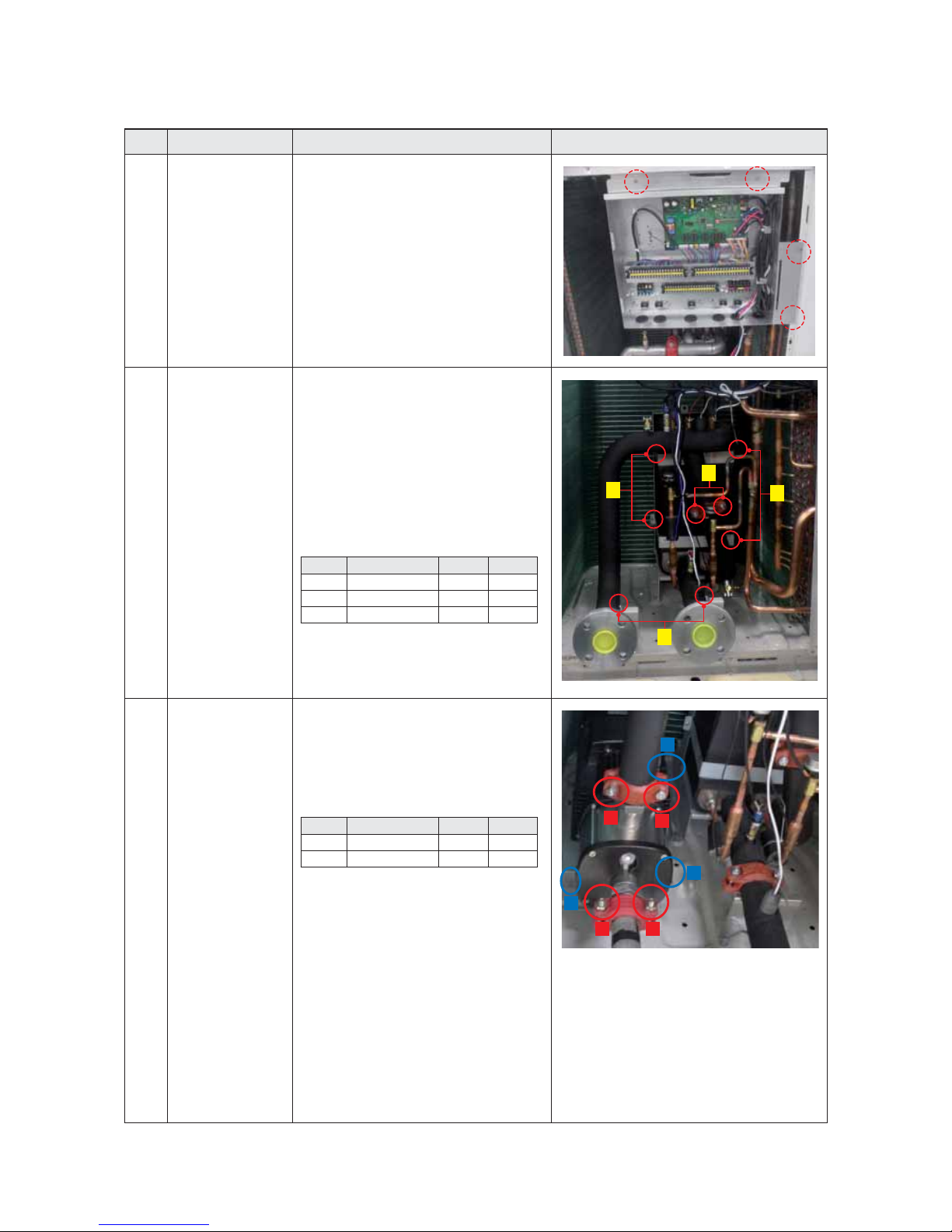
13) Separates the fixed screw of pump terminal. (using - screw driver or exclusive tool)
14) Connect power wire to terminal as a existing assembly condition.
Connection mothod of pump have Y-connection & Delta connection method.
This model must be connected by Y-connection method because it uses 3-Phase
high boltage power.
15) When you replace the Pump, replace it to purchase together with
the Cable Holder(DB61-0091E).
The gap between steel plate and nut must be 1.3~1.5mm when you assemble
the cable holder.
Gap :
1.4 ± 0.1mm
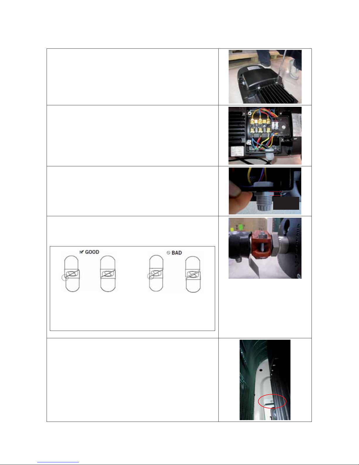
16) Please reassemble in reverse order of disassembly.
Bolt torque at time of coupling tightening : 200±10% kgfcm.
After reassembly, please reassemble so that diagonal line part of coupling side is
not intersected each other.
PROPERLY
ASSEMBLED JOINT
POSITIVE OFFSET
WITH BOLT PAD
CONTACT
PROPERLY
ASSEMBLED JOINT
NEUTRAL OFFSET
WITH BOLT PAD
CONTACT
IMPROPERLY
ASSEMBLED JOINT
NEGATIVE
OFFSET
IMPROPERLY
ASSEMBLED JOINT
BOLT PAD
GAP
17) When you insert ASSY Pump, set to the groove of Base & Bracket and then
reassemble adjusting Bolt Hole.
18
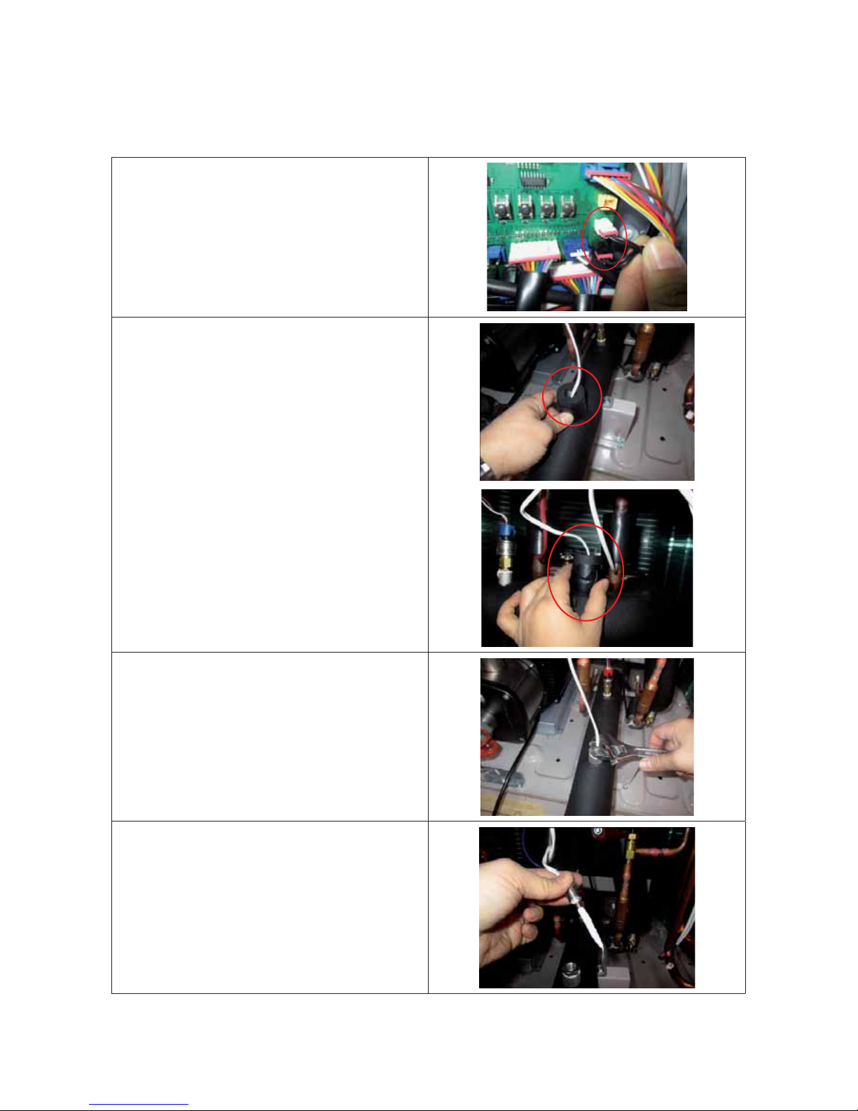
3-3-2. Temperature sensor & Pressure sensor in the water pipe side
- Exchange method of the water temperature sensor
1) Power off before starting on work.
2) Unscrews the fixed screw of CABINET FRONT and C-BOX.
3) Separate the connector from PBA
4) Separate Insu protecting the temperature sensor.
5) Separate the temperature sensor by using spanner.
6) Separate the temperature sensor.
It is applied Thermal Grease for an accurate temperature
measurement.
Ŷ Cover the temperature sensor with Insu so that it is not affected from
the outside.
- Bolt torque : 120±10% kgfcm
19
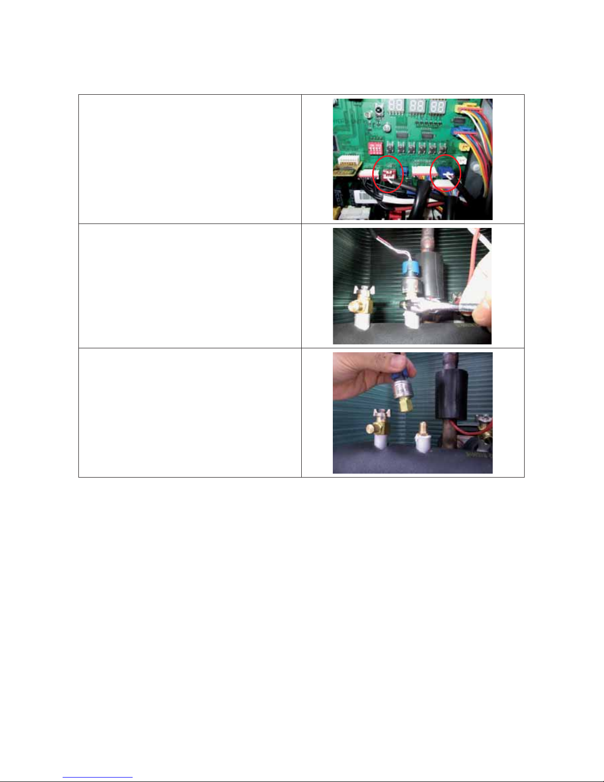
- Exchange method of the pressure sensor
1) Power off before starting on work.
2) Close the valve connected to inlet/outlet of main water pipe.
3) Drain all water of water pipe connected to DVM CHILLER.
4) Unscrews the fixed screw of CABINET FRONT and C-BOX.
5) Separate the connector from PBA.
6) Separate the pressure sensor by using spanner.
7) Replace with the new pressure sensor.
Bolt torque : 120±10% kgfcm
20
3-3-3. Plate type heat exchanger PHE
1) Power off before starting on work.
2) Close the valve connected to inlet/outlet of main water pipe.
3) Drain all water of water pipe connected to DVM CHILLER.
4) Unscrews the screw of inlet/outlet water pipe flange connected
to DVM CHILLER.
5) Unscrews the fixed screw of CABINET FRONT.
6) Separates wire of cycle parts connected to ASSY PHE from C-BOX.
7) Connect the refrigerant reclaimer in the charging port,
Recovering the refrigerant sealed in the product.
Use only charging port charging, recovery of refrigerants.
8) Separate the four points of the pipe connected to ASSY PHE
by welding .
21
9) Unscrew the screw of coupling connecting the two PHE in series.
10) Separate 6 screws of Bracket fixing ASSY PHE.
11) Please reassemble in reverse order of disassembly.
- Bolt torque at time of coupling tightening : 200±10% kgfcm
22
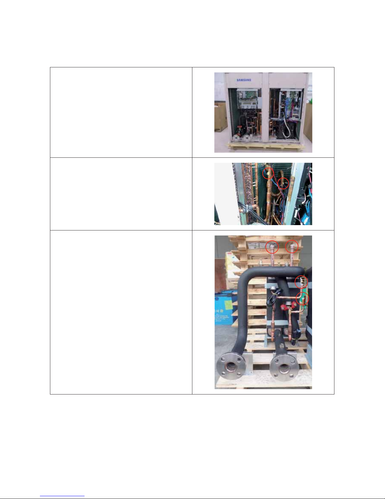
Binding Wire1
■ AG042/056/070KSV666 Series
A
B
C
location Specifications Used parts
A Binds a EEV, Pressure sensor, Temperature sensor, Water temperature sensor by Cable-Tie.
6501-001110 (L200) :
Cable Tie
B Binds a High pressure switch, Oil return valve by Cable-Tie using Insu.
C Binds a High pressure sensor, EVI, Hot gas valve by Cable-Tie using Insu.
Cable Tie Holder Wire Etc.
23
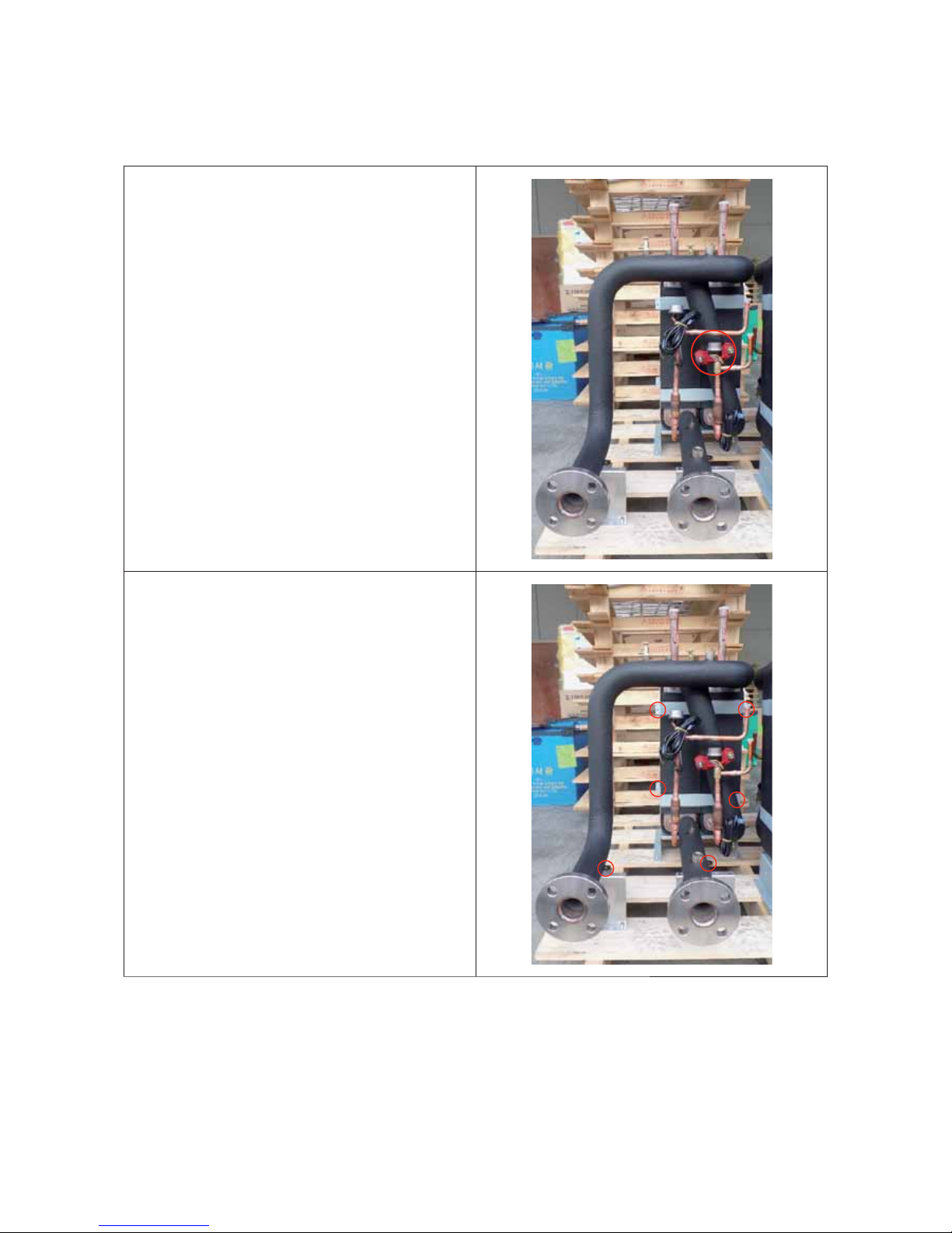
Binding Wire2
■ AG042/056/070KSV666 Series
location Specifications Used parts
D
Binds a Vapor injection valve, High-voltage switch, Oil return valve, High
pressure sensor, EVI, Hot gas valve by Cable-Tie using Insu.
6501-001110 (L200) : Cable Tie
E Binds a Low pressure sensor , Temperature sensor bundle by Cable-Tie.
F
Binds a Vapor injection valve, High-voltage switch, Oil return valve, High
pressure sensor, EVI, Hot gas valve, Low pressure sensor , Temperature sensor by
Holder wire.
6501-001107 (L368) : Cable Tie
G 4Way valve, EVI EEV valve
Cable Tie Holder Wire Etc.
G
D
E
F

24
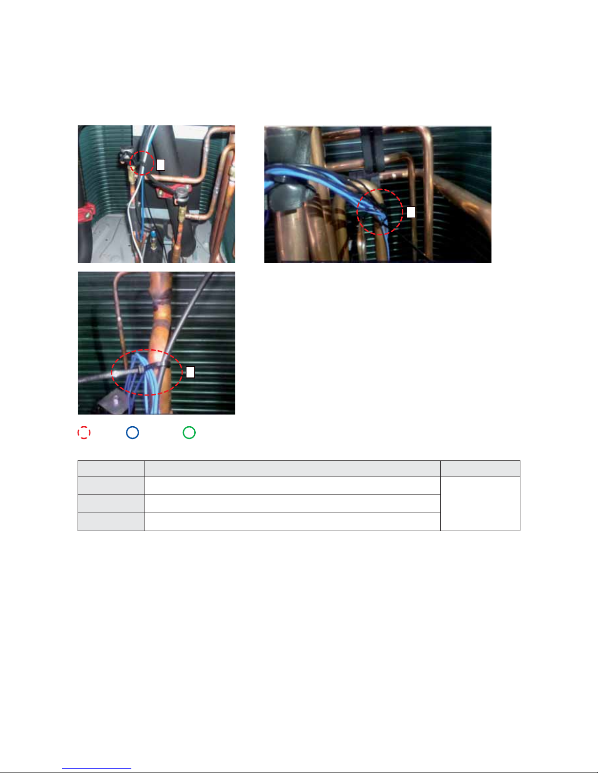
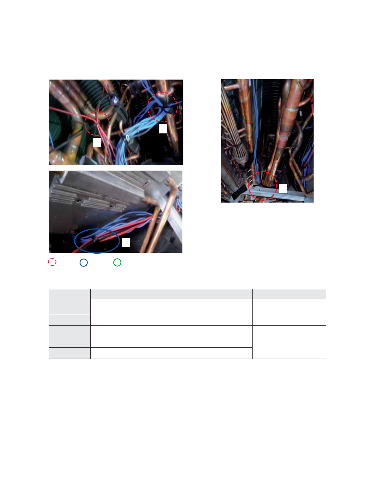
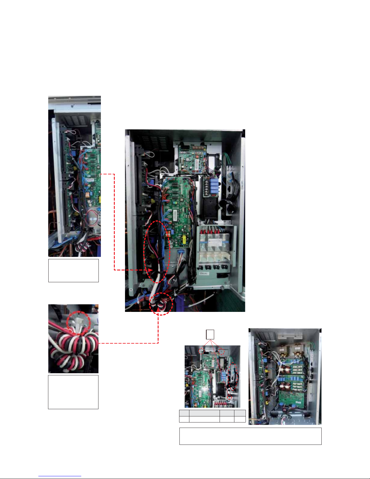
Binding Wire3
■ AG042/056/070KSV666 Series
location Specifications Used parts
H Binds a Sub cooler temperature sensor 2 kinds by Cable-Tie.
6501-001107 (L368) : Cable Tie
I
Binds a EEV coil, Cond out temperature sensor, Sub cooler temperature sensor
3 kinds, Oil return valve by Cable-Tie.
J
Binds a Communication wire, Power wire, Motor wire, Suction temperature
sensor by Holder wire.
DB61-00206A
K
Binds a Communication wire, Power wire, Motor wire, Suction temperature
sensor by Holder wire.
L Binds a Motor wire, Power wire by Holder wire.
M
Binds a Motor wire, Power wire, Communication wire, Hydro part wire
bundle by Holder wire.
N Binds a Hydro part wire bundle by Holder wire.
O COND OUT, ACCUM OIL RETURN VALVE, Temperature Senser
2 kinds
FELT VELCRO
L
M
N
J
K
Cable Tie Holder Wire Etc.
H
I
O
25
Binding Wire4
■ AG042/056/070KSV666 Series
Binds a Comp wire-core
to Bracket beam control
box using large size CableTie(350mm).
Binds a Comp wire by
Holder wire.
Remove the 3 screws and separate the connector and then separate the double
layer structure of Control Box.
1
No Code SPEC Q'ty
1 6002-001149 M4 3
26
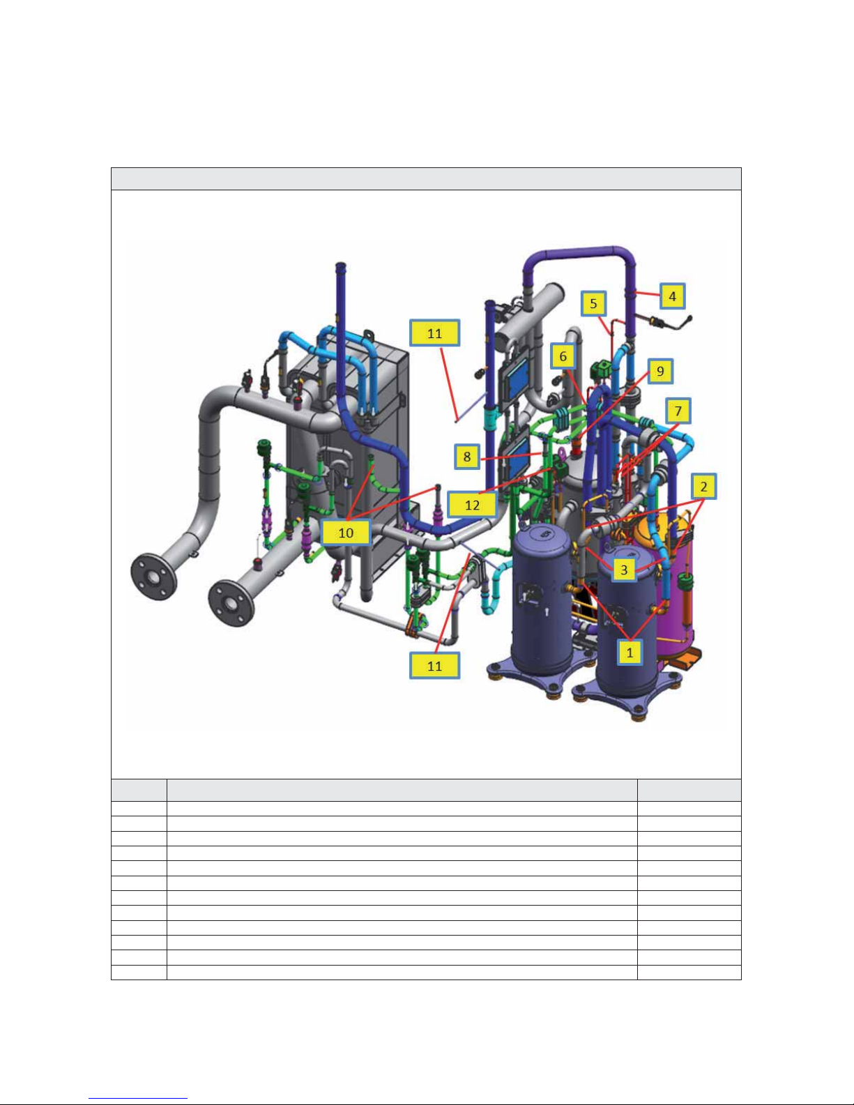
[Reference Sheet]
Pipe Welding Position
■ AG042/056/070KSV666 Series
Front welding part 2
No. Welding Position Q'ty
1 Comp + Discharge 2
2 Comp + Suction 2
3 Comp + Vpaor Injection 2
4 Oil Sepa Out + 4way 1
5 Oil Sepa Out + Hot Gas 1
6 4Way + Hot Gas 1
7 Sution + Oil Return 2
8 Vapor Injection + EVI Bypass 1
9 Accum + 4Way 1
10 EEV + Cond Out 2
11 Pinch Pipe 2
12 Subcooler + Receicer Tube 1
All model's pipe welding position is same.
 Loading...