

Samsung AE120JXEDEH, AE090JXEDEH, AE120JXEDGH, AE140JXEDGH, AE160JXEDGH Installation Manual
...
AE090JXEDEH
AE120JXEDEH
AE140JXEDEH
AE160JXEDEH
AE090JXEDGH
AE120JXEDGH
AE140JXEDGH
AE160JXEDGH
Air to Water Heat Pump
Outdoor Unit
installation manual
imagine the possibilities
Thank you for purchasing this Samsung product.
EN
ES FR IT PT DE
DB68-05328A-05
ENGLISH-2
Contents
PREPARATION
Safety precautions . .. .. .. .. .. .. .. .. .. .. .. .. .. .. .. .. .. .. .. .. .. .. .. .. .. .. .. .. .. .. .. .. .. .. .. .. .. .. .. .. .. .. .. .. .. .. .. .. .. .. .. 3
Product specications . .. .. .. .. .. .. .. .. .. .. .. .. .. .. .. .. .. .. .. .. .. .. .. .. .. .. .. .. .. .. .. .. .. .. .. .. .. .. .. .. .. .. .. .. .. .. .. .. .. 5
INSTALLATION
Outdoor unit specication . . .. .. .. .. .. .. .. .. .. .. .. .. .. .. .. .. .. .. .. .. .. .. .. .. .. .. .. .. .. .. .. .. .. .. .. .. .. .. .. .. .. .. .. .. .. .. . 6
Main components . .. .. .. .. .. .. .. .. .. .. .. .. .. .. .. .. .. .. .. .. .. .. .. .. .. .. .. .. .. .. .. .. .. .. .. .. .. .. .. .. .. .. .. .. .. .. .. .. .. .. .. 7
Installing the unit . .. .. .. .. .. .. .. .. .. .. .. .. .. .. .. .. .. .. .. .. .. .. .. .. .. .. .. .. .. .. .. .. .. .. .. .. .. .. .. .. .. .. .. .. .. .. .. .. .. .. .. . 8
Electrical connections .. .. .. .. .. .. .. .. .. .. .. .. .. .. .. .. .. .. .. .. .. .. .. .. .. .. .. .. .. .. .. .. .. .. .. .. .. .. .. .. .. .. .. .. .. .. .. .. .. . 16
Connecting the cable . . .. .. .. .. .. .. .. .. .. .. .. .. .. .. .. .. .. .. .. .. .. .. .. .. .. .. .. .. .. .. .. .. .. .. .. .. .. .. .. .. .. .. .. .. .. .. .. .. . 17
Refrigerant piping work .. .. .. .. .. .. .. .. .. .. .. .. .. .. .. .. .. .. .. .. .. .. .. .. .. .. .. .. .. .. .. .. .. .. .. .. .. .. .. .. .. .. .. .. .. .. .. .. 25
Checking correct grounding . . .. .. .. .. .. .. .. .. .. .. .. .. .. .. .. .. .. .. .. .. .. .. .. .. .. .. .. .. .. .. .. .. .. .. .. .. .. .. .. .. .. .. .. .. .. 36
Setting the option switch and function of the keys . .. .. .. .. .. .. .. .. .. .. .. .. .. .. .. .. .. .. .. .. .. .. .. .. .. .. .. .. .. .. .. .. .. .. . 36
Pump down procedure .. .. .. .. .. .. .. .. .. .. .. .. .. .. .. .. .. .. .. .. .. .. .. .. .. .. .. .. .. .. .. .. .. .. .. .. .. .. .. .. .. .. .. .. .. .. .. .. . 40
Completing the installation . . .. .. .. .. .. .. .. .. .. .. .. .. .. .. .. .. .. .. .. .. .. .. .. .. .. .. .. .. .. .. .. .. .. .. .. .. .. .. .. .. .. .. .. .. .. . 42
Final checks and trial operation . . .. .. .. .. .. .. .. .. .. .. .. .. .. .. .. .. .. .. .. .. .. .. .. .. .. .. .. .. .. .. .. .. .. .. .. .. .. .. .. .. .. .. .. . 43
OTHERS
Trouble shooting .. .. .. .. .. .. .. .. .. .. .. .. .. .. .. .. .. .. .. .. .. .. .. .. .. .. .. .. .. .. .. .. .. .. .. .. .. .. .. .. .. .. .. .. .. .. .. .. .. .. .. . 44
Error codes .. .. .. .. .. .. .. .. .. .. .. .. .. .. .. .. .. .. .. .. .. .. .. .. .. .. .. .. .. .. .. .. .. .. .. .. .. .. .. .. .. .. .. .. .. .. .. .. .. .. .. .. .. .. . 44
COMMISSION REGULATION (EU) No 813/2013
I)
. .. .. .. .. .. .. .. .. .. .. .. .. .. .. .. .. .. .. .. .. .. .. .. .. .. .. .. .. .. .. .. .. .. .. .. .. 46
COMMISSION DELEGATED REGULATION (EU) No 811/2013
i)
. . .. .. .. .. .. .. .. .. .. .. .. .. .. .. .. .. .. .. .. .. .. .. .. .. .. .. .. .. .. . 66
Correct Disposal of This Product
(Waste Electrical & Electronic Equipment)
(Applicable in countries with separate collection systems)
This marking on the product, accessories or literature indicates that the product and its electronic accessories (e.g.
charger, headset, USB cable) should not be disposed of with other household waste at the end of their working life. To
prevent possible harm to the environment or human health from uncontrolled waste disposal, please separate these
items from other types of waste and recycle them responsibly to promote the sustainable reuse of material resources.
Household users should contact either the retailer where they purchased this product, or their local government oce,
for details of where and how they can take these items for environmentally safe recycling.
Business users should contact their supplier and check the terms and conditions of the purchase contract. This product
and its electronic accessories should not be mixed with other commercial wastes for disposal.

ENGLISH-3
01 PREPARATION
Safety precautions
Carefully follow the precautions listed as below because they are essential to guarantee the safety of SAMSUNG product.
WARNING
• Always disconnect a power supply of Air-Water Heat Pump before servicing it or
accessing components inside the unit.
•
Verify that installation and testing operations shall be performed by qualied personnel.
•
To prevent serious damage on the system and injuries to users, precautions and other
notices shall be observed.
Warning
f Carefully read the content of this manual before installing the air to water heat pump and store the manual in a safe place
in order to be able to use it as reference after installation.
f
For maximum safety, installers should always carefully read the following warnings.
f
Store the operation and installation manual in a safe location and remember to hand it over to the new owner if the Air to
Water Heat pump is sold or transferred.
f Store the user and installation manual in a safe location and remember to hand it over to the new owner if the air to
water heat pump is sold or transferred.
f
This manual explains how to install Air-Water Heat Pump. The use of other types of units with dierent control systems
may damage the units and invalidate the warranty. The manufacturer shall not be responsible for damages arising from
the use of non compliant units.
f
The manufacturer shall not be responsible for damage originating from unauthorized changes or the improper
connection of electric and hydraulic lines. Failure to comply with these instructions or to comply with the requirements
set forth in the “Operating limits” table, included in the manual, shall immediately invalidate the warranty.
f
Failure to comply with these instructions or to comply with the requirement on the Operating Range (Heat : -25~35°C/
Cool: 10~46°C) set forth in the Product Specication (p.6) shall immediately invalidate the warranty.
f
Do not use the units if you see some damages on the units and recognize something bad such as loud noisy, smell of
burning.
f
In order to prevent electric shocks, res or injuries, always stop the unit, disable the protection switch and contact
SAMSUNG’s technical support if the unit produces smoke, if the power cable is hot or damaged or if the unit is very noisy.
f
Always remember to inspect the unit, electric connections, refrigerant tubes and protections regularly. These operations
shall be performed by qualied personnel only.
f
The unit contains moving parts and electrical parts, which should always be kept out of the reach of children.
f
Do not attempt to repair, move, alter or reinstall the unit by unauthorized personnel, these operations may cause product
damage, electric shocks and res.
f
Do not place containers with liquids or other objects on the unit.
f
All the materials used for the manufacture and packaging of the air to water heat pump are recyclable.
f
The packing material and exhaust batteries of the remote controller(optional) must be disposed of in accordance with
local regulations.
f The air to water heat pump contains a refrigerant that has to be disposed of as special waste. At the end of its life cycle,
the heat pump must be disposed of in authorized centers or returned to the retailer so that it can be disposed of correctly
and safely.
f
Wear protective gloves to unpack, move, install, and service the unit to avoid your hands being injured by the edge of the
parts.
f
Do not touch the internal parts (water pipes, refrigerant pipes, heat exchangers, etc) while running the units. And if you
need to adjust and touch the units, have enough time for the unit can be cooled and be sure to wear protective gloves.
f In case of refrigerant leakage, try to avoid getting in contact with the refrigerant because this could result in severe
wounds.
ENGLISH-4
Safety precautions
f When you install the Air to water heat pump in a small room, you must consider a proper ventilation to prevent a leakage
level within the maximum permissible limit.
- In that case, you may die from suocation by some possibility.
f
Make sure to safely dispose of packing materials. Packing materials, such as nails and other metal or wooden pallets may
cause children get injured.
f
Inspect the product shipped and check if damaged during transport. If the product has some damages, DO NOT INSTALL
and immediately discuss about the damages with the carrier or retailer (if the installer or the authorized technician has
collected the material from the retailer.)
f
Our units shall be installed in compliance with the spaces described in the installation manual, to ensure accessibility
from both sides and allow repairs or maintenance operations to be carried out. If the units installed without complying
with procedures described in manual, additional expenses can be asked because special harnesses, ladders, scaolding
or any other elevation system for repair service will NOT be considered part of the warranty and will be charged to the
end customer.
f
Always make sure that the power supply is compliant with local safety standards.
f
Verify that the voltage and frequency of the power supply comply with the specications and input power is sucient to
ensure the operation of any other domestic appliance connected to the same electric lines. Always verify that the cut-o
and protection switches are suitably selected.
f
Always verify that electric connections (cable entry, section of leads, protections…) are compliant with the electric
specications and with the instructions provided in the wiring scheme. Always verify that all connections comply with
the standards applicable to the installation of air to water heat pumps. Devices disconnected from the power supply
should be completely disconnected in the condition of overvoltage category.
f
Do not connect the earth wire to the gas pipe or water pipe, lighting rod, surge absorber, or telephone earth wire. If
earthing is not complete, it may cause an electric shock or re.
f
Be sure to install both an earth leakage detector and circuit breaker with specied capacity in accordance with relevant
local and national regulations.
- If it is not installed properly, it may cause electric shocks and re.
f
Make sure that the condensed water runs well out of the unit at low ambient temperature. Drain pipe and cond heater
can frost/ice can not grow. If drain work is not eective for releasing condensed water, it can make the units get damaged
by massive ice and system can be stop , covered by ice.
f
Install the power cable and communication cable of the indoor and outdoor unit at least 1m away from the electric
appliance.
f
Protect the unit from rats or small animals. If an animal makes a contact with the electric parts, it can cause malfunctions,
smoke or re. Please instruct the customer to keep the area around the unit clean.
f
Do not disassemble and alter the heater at your own discretion.
f
This appliance is not intended for use by persons (including children) with reduced physical, sensory or mental
capabilities, or lack of experience and knowledge, unless they have been given supervision or instruction concerning use
of the appliance by a person responsible for their safety. Children should be supervised to ensure that they do not play
with the appliance.
f
For use in Europe : This appliance can be used by children aged from 8 years and above and persons with reduced
physical, sensory or mental capabilities or lack of experience and knowledge if they have been given supervision or
instruction concerning use of the appliance in a safe way and understand the hazards involved. Children shall not play
with the appliance. Cleaning and user maintenance shall not be made by children without supervision.
f
Be sure not to perform power cable modication, extension wiring, and multiple wire connection.
- It may cause electric shock or re due to poor connection, poor insulation, or current limit override.
- When extension wiring is required due to power line damage, refer to "How to connect your extended power cables" in
the installation manual.

ENGLISH-5
01 PREPARATION
Product specications
Product line-up
Line-up Remark
Heat pump units
Chassis
-
Model name
AE090JXEDEH
AE090JXEDGH
AE120JXEDEH
AE140JXEDEH
AE160JXEDEH
AE120JXEDGH
AE140JXEDGH
AE160JXEDGH
Accessories
f Keep supplied accessories until the installation is nished.
f
Hand the installation manual over to the customer after nishing installation.
f
The quantities are indicated in parentheses.
f
The base heater inside outdoor unit works in accordance with the weather of outdoor.
Installation manual (1) Drain plug (1) Rubber Leg(4) Drain cap (3)
ENGLISH-6
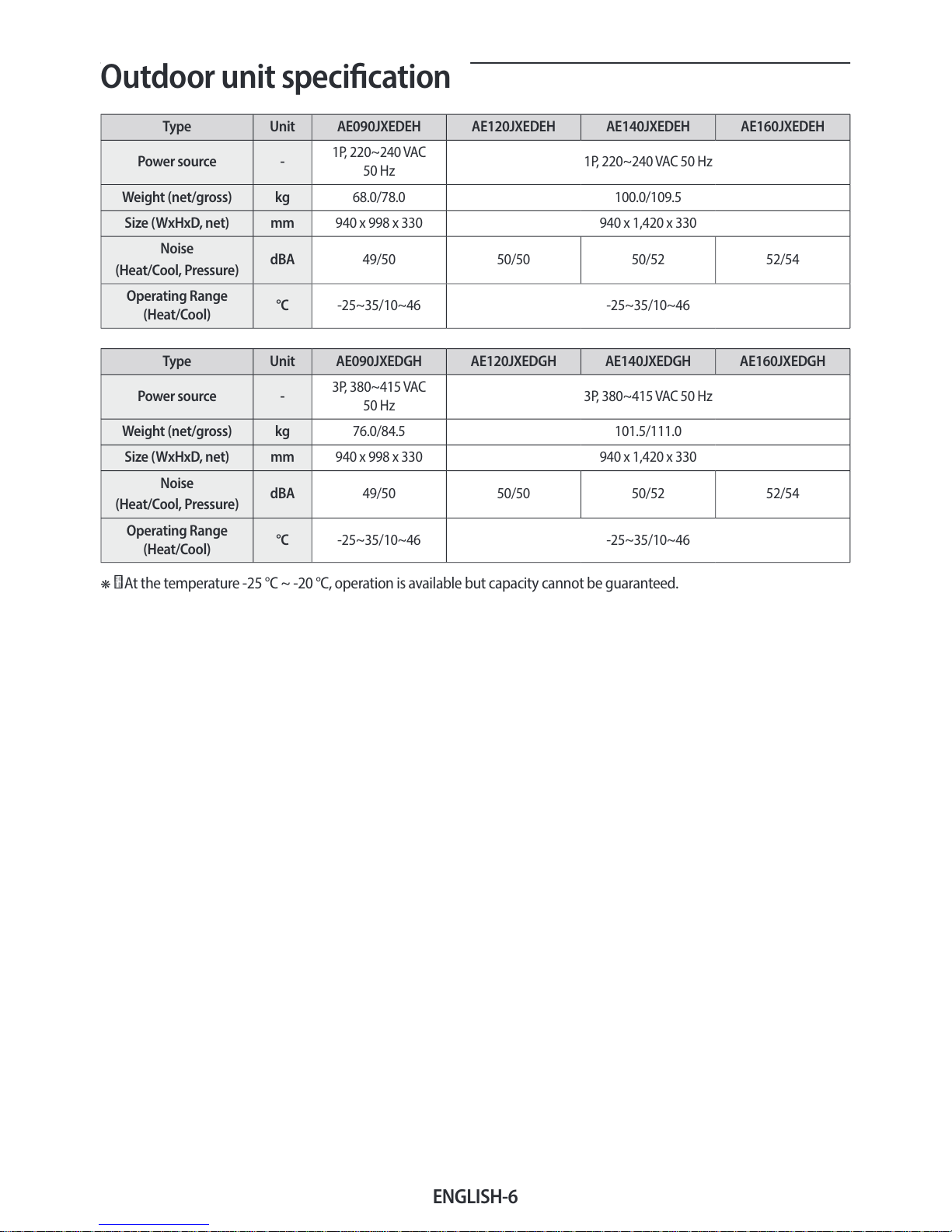
Outdoor unit specication
Type Unit AE090JXEDEH AE120JXEDEH AE140JXEDEH AE160JXEDEH
Power source -
1P, 220~240VAC
50Hz
1P, 220~240VAC 50Hz
Weight (net/gross) kg 68.0/78.0 100.0/109.5
Size (WxHxD, net) mm 940 x 998 x 330 940 x 1,420 x 330
Noise
(Heat/Cool, Pressure)
dBA 49/50 50/50 50/52 52/54
Operating Range
(Heat/Cool)
°C -25~35/10~46 -25~35/10~46
Type Unit AE090JXEDGH AE120JXEDGH AE140JXEDGH AE160JXEDGH
Power source -
3P, 380~415VAC
50Hz
3P, 380~415VAC 50Hz
Weight (net/gross) kg 76.0/84.5 101.5/111.0
Size (WxHxD, net) mm 940 x 998 x 330 940 x 1,420 x 330
Noise
(Heat/Cool, Pressure)
dBA 49/50 50/50 50/52 52/54
Operating Range
(Heat/Cool)
°C -25~35/10~46 -25~35/10~46
❋ At the temperature -25°C ~ -20°C, operation is available but capacity cannot be guaranteed.
ENGLISH-7
02 INSTALLATION
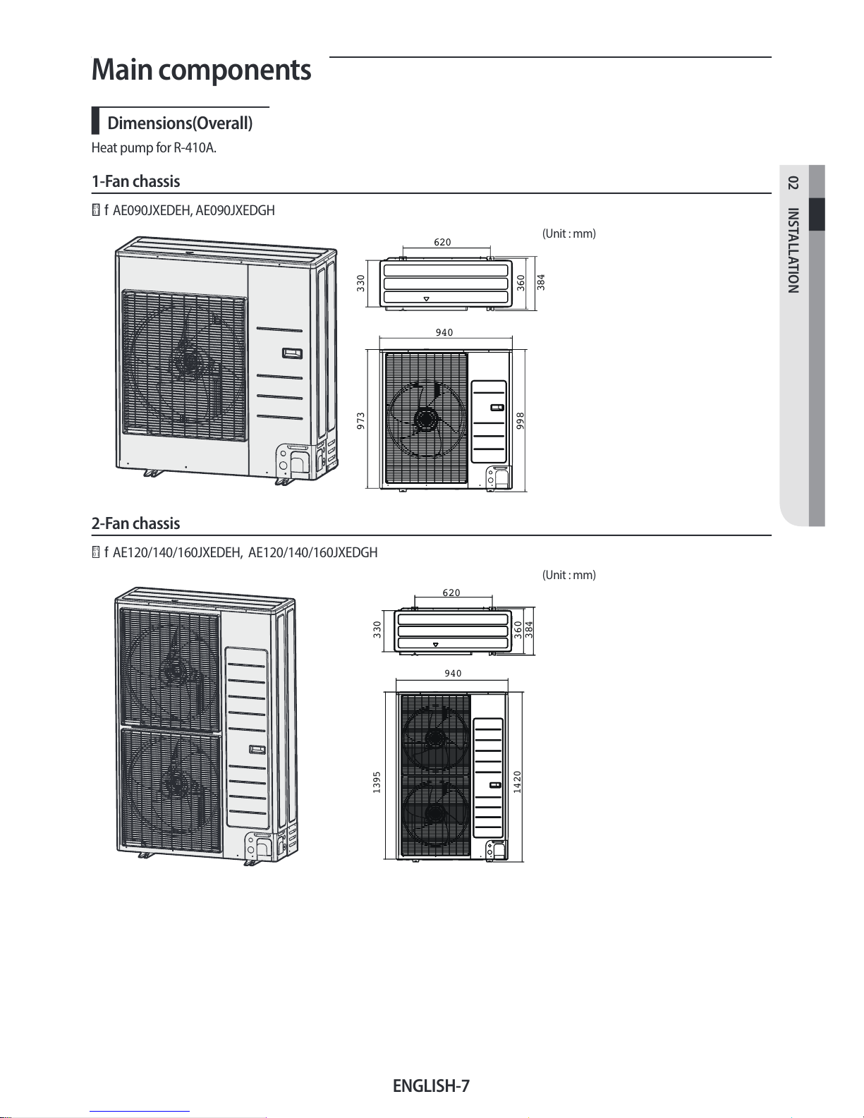
Main components
Dimensions(Overall)
Heat pump for R-410A.
1-Fan chassis
f AE090JXEDEH, AE090JXEDGH
620
940
330973
998
360
384
(Unit : mm)
2-Fan chassis
f AE120/140/160JXEDEH, AE120/140/160JXEDGH
620
330
360
384
940
1395
1420
(Unit : mm)
ENGLISH-8
Installing the unit
Deciding on where to install the outdoor unit
Decide the installation location regarding the following condition and obtain the user’s approval.
f
The outdoor unit must not be placed on its side or upside down, as the compressor lubrication oil will run into the cooling
circuit and seriously damage the unit.
f
Choose a location that is dry and sunny, but not exposed to direct sunlight or strong winds.
f
Do not block any passageways or thoroughfares.
f
Choose a location where the noise of the Air to Water Heat Pump when running and the discharged air do not disturb
any neighbours.
f Choose a position that enables the pipes and cables to be easily connected to the other hydrauric system.
f
Install the outdoor unit on a at, stable surface that can support its weight and does not generate any unnecessary noise
and vibration.
f Position the outdoor unit so that the air ow directly stream towards the open area.
f
Place the outdoor unit where there are no plants and animals because they may cause malfunction of outdoor unit.
f
Maintain sucient clearance around the outdoor unit, especially from a radio, computer, stereo system, etc.
f
When installing the outdoor unit near seashore, make sure it is not directly exposed to sea breeze. If you can not nd an
adequate place without direct sea breeze, make sure to apply anti-corrosion coating on the heat exchanger.
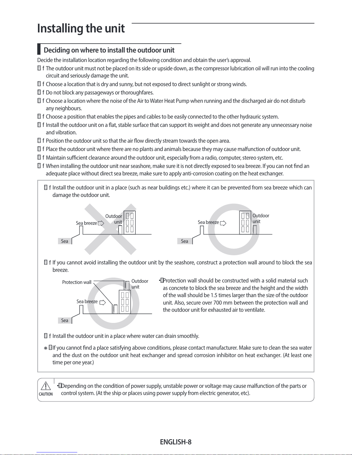
f
Install the outdoor unit in a place (such as near buildings etc.) where it can be prevented from sea breeze which can
damage the outdoor unit.
f
If you cannot avoid installing the outdoor unit by the seashore, construct a protection wall around to block the sea
breeze.
f
Install the outdoor unit in a place where water can drain smoothly.
•
Protection wall should be constructed with a solid material such
as concrete to block the sea breeze and the height and the width
of the wall should be 1.5 times larger than the size of the outdoor
unit. Also, secure over 700mm between the protection wall and
the outdoor unit for exhausted air to ventilate.
Sea
Sea breeze
Outdoor
unit
Sea
Sea breeze
Outdoor
unit
Sea
Sea breeze
Outdoor
unit
Protection wall
❋
If you cannot nd a place satisfying above conditions, please contact manufacturer. Make sure to clean the sea water
and the dust on the outdoor unit heat exchanger and spread corrosion inhibitor on heat exchanger. (At least one
time per one year.)
• Depending on the condition of power supply, unstable power or voltage may cause malfunction of the parts or
control system. (At the ship or places using power supply from electric generator, etc).
CAUTION
ENGLISH-9
02 INSTALLATION
f Do not install the Air to Water Heat Pump in following places.
•
The place where there is mineral oil or arsenic acid. There is a chance that parts may get damaged due to burned resin.
The capacity of the heat exchanger may reduce or the Air to Water Heat pump may be out of order.
•
The place where corrosive gas such as sulfurous acid gas generates from the vent pipe or air outlet. The copper pipe or
connection pipe may corrode and refrigerant may leak.
•
The place where there is a danger of existing combustible gas, carbon ber or ammable dust. The place where thinner
or gasoline is handled.
• This device must be installed according to the national electrical rules.
•
With an outdoor unit having net weight upper than 60kg, we suggest do not install it suspended on wall, but
considering oor standing one.
CAUTION
f If the outdoor unit is installed at a height, ensure that its base is rmly xed in position.
f
Make sure that the water dripping from the drain hose runs away correctly and safely.
f
When you install the outdoor unit at wayside, you should install it above 2m height or make sure that the heat from the
outdoor unit shouldn't be in direct contact with passersby. (The ground for application :The revision of regulation for
facility in building by the law of the Ministry of Construction and Transportation.
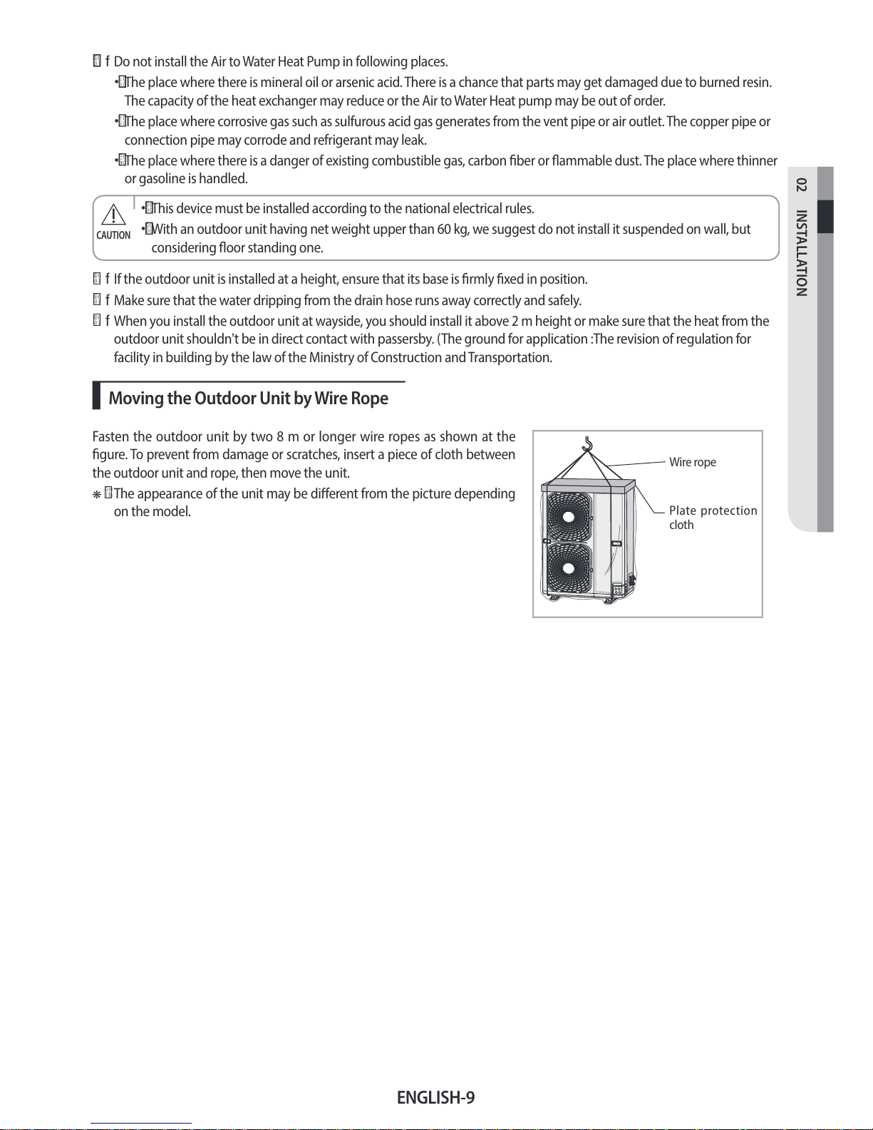
Moving the Outdoor Unit by Wire Rope
Fasten the outdoor unit by two 8m or longer wire ropes as shown at the
gure. To prevent from damage or scratches, insert a piece of cloth between
the outdoor unit and rope, then move the unit.
❋
The appearance of the unit may be dierent from the picture depending
on the model.
Plate protection
cloth
Wire rope
ENGLISH-10
Installing the unit
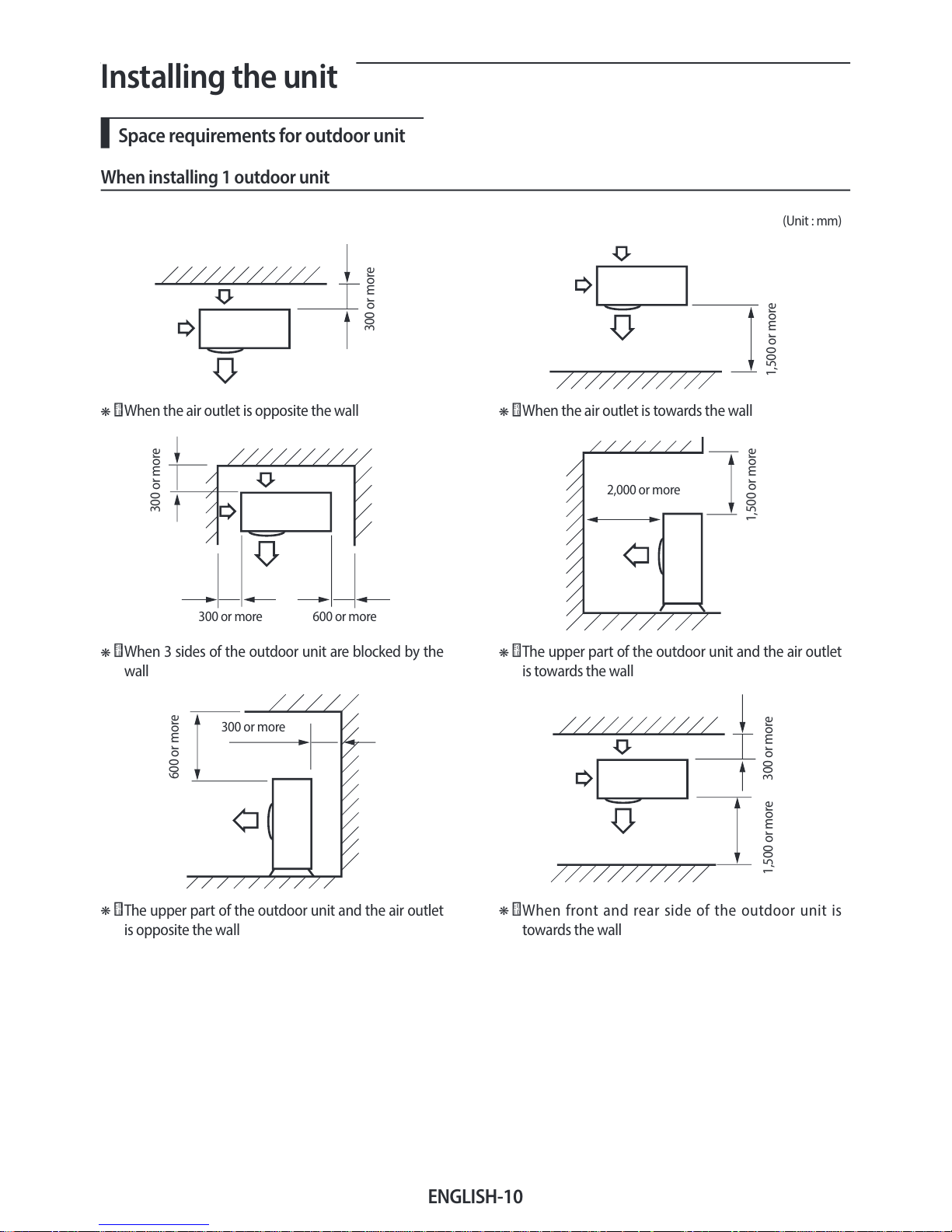
Space requirements for outdoor unit
When installing 1 outdoor unit
(Unit : mm)
300 or more
1,500 or more
❋
When the air outlet is opposite the wall
❋
When the air outlet is towards the wall
300 or more
300 or more 600 or more
1,500 or more
2,000 or more
❋
When 3 sides of the outdoor unit are blocked by the
wall
❋
The upper part of the outdoor unit and the air outlet
is towards the wall
600 or more
300 or more
1,500 or more
300 or more
❋
The upper part of the outdoor unit and the air outlet
is opposite the wall
❋
When front and rear side of the outdoor unit is
towards the wall
ENGLISH-11
02 INSTALLATION
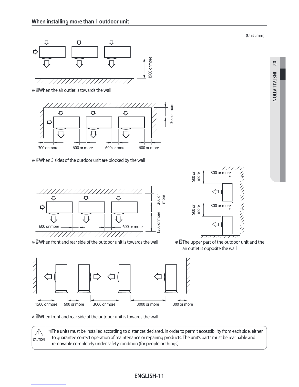
When installing more than 1 outdoor unit
(Unit : mm)
1500 or more
❋
When the air outlet is towards the wall
300 or more
300 or more 600 or more 600 or more 600 or more
❋
When 3 sides of the outdoor unit are blocked by the wall
300 or
more
1500 or more
600 or more
600 or more
500 or
more
500 or
more
300 or more
300 or more
❋
When front and rear side of the outdoor unit is towards the wall
❋
The upper part of the outdoor unit and the
air outlet is opposite the wall
1500 or more 600 or more 3000 or more 300 or more3000 or more
❋
When front and rear side of the outdoor unit is towards the wall
• The units must be installed according to distances declared, in order to permit accessibility from each side, either
to guarantee correct operation of maintenance or repairing products. The unit’s parts must be reachable and
removable completely under safety condition (for people or things).
CAUTION
ENGLISH-12
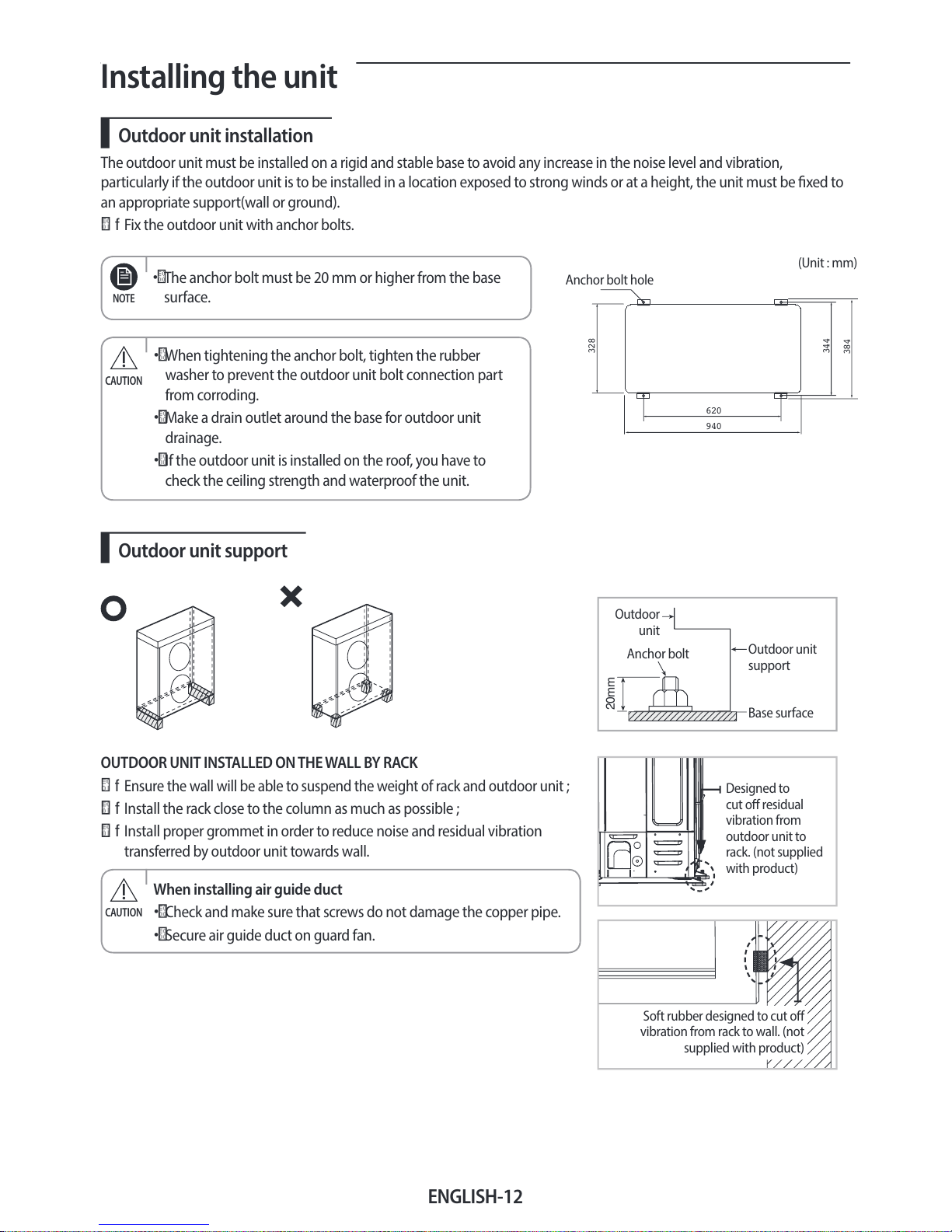
Installing the unit
Outdoor unit installation
The outdoor unit must be installed on a rigid and stable base to avoid any increase in the noise level and vibration,
particularly if the outdoor unit is to be installed in a location exposed to strong winds or at a height, the unit must be xed to
an appropriate support(wall or ground).
f
Fix the outdoor unit with anchor bolts.
• The anchor bolt must be 20mm or higher from the base
surface.
NOTE
(Unit : mm)
620
940
328
344
384
Anchor bolt hole
• When tightening the anchor bolt, tighten the rubber
washer to prevent the outdoor unit bolt connection part
from corroding.
•
Make a drain outlet around the base for outdoor unit
drainage.
•
If the outdoor unit is installed on the roof, you have to
check the ceiling strength and waterproof the unit.
CAUTION
Outdoor unit support
20mm
Anchor bolt
Outdoor
unit
Base surface
Outdoor unit
support
OUTDOOR UNIT INSTALLED ON THE WALL BY RACK
f Ensure the wall will be able to suspend the weight of rack and outdoor unit ;
f Install the rack close to the column as much as possible ;
f
Install proper grommet in order to reduce noise and residual vibration
transferred by outdoor unit towards wall.
When installing air guide duct
•
Check and make sure that screws do not damage the copper pipe.
•
Secure air guide duct on guard fan.
CAUTION
Soft rubber designed to cut o
vibration from rack to wall. (not
supplied with product)
Designed to
cut o residual
vibration from
outdoor unit to
rack. (not supplied
with product)
ENGLISH-13
02 INSTALLATION
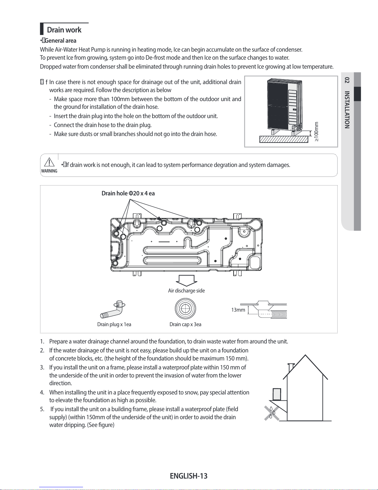
Drain work
• General area
While Air-Water Heat Pump is running in heating mode, Ice can begin accumulate on the surface of condenser.
To prevent Ice from growing, system go into De-frost mode and then Ice on the surface changes to water.
Dropped water from condenser shall be eliminated through running drain holes to prevent Ice growing at low temperature.
f
In case there is not enough space for drainage out of the unit, additional drain
works are required. Follow the description as below
- Make space more than 100mm between the bottom of the outdoor unit and
the ground for installation of the drain hose.
- Insert the drain plug into the hole on the bottom of the outdoor unit.
- Connect the drain hose to the drain plug.
- Make sure dusts or small branches should not go into the drain hose.
≥100mm
• If drain work is not enough, it can lead to system performance degration and system damages.
WARNING
Drain cap x 3eaDrain plug x 1ea
Drain hole Φ20 x 4 ea
Air discharge side
13mm
1. Prepare a water drainage channel around the foundation, to drain waste water from around the unit.
2. If the water drainage of the unit is not easy, please build up the unit on a foundation
of concrete blocks, etc. (the height of the foundation should be maximum 150mm).
3. If you install the unit on a frame, please install a waterproof plate within 150mm of
the underside of the unit in order to prevent the invasion of water from the lower
direction.
4. When installing the unit in a place frequently exposed to snow, pay special attention
to elevate the foundation as high as possible.
5. If you install the unit on a building frame, please install a waterproof plate (eld
supply) (within 150mm of the underside of the unit) in order to avoid the drain
water dripping. (See gure)
ENGLISH-14
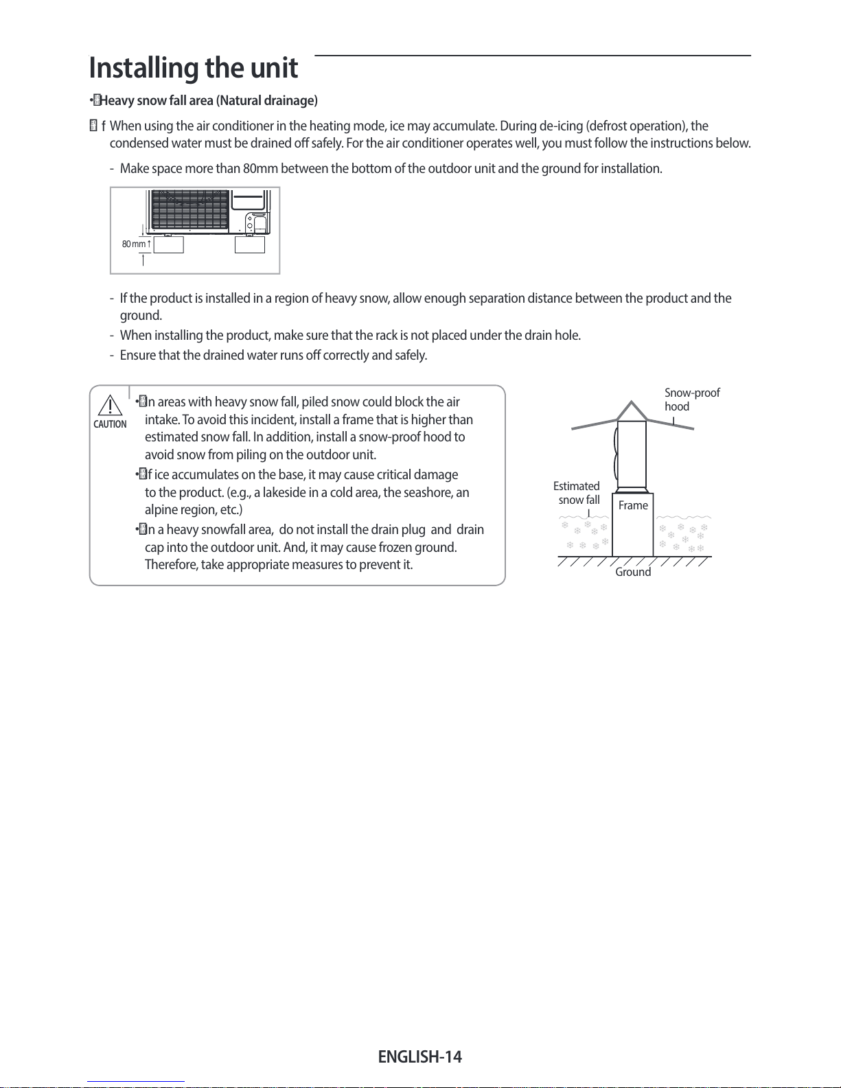
Installing the unit
• Heavy snow fall area (Natural drainage)
f
When using the air conditioner in the heating mode, ice may accumulate. During de-icing (defrost operation), the
condensed water must be drained o safely. For the air conditioner operates well, you must follow the instructions below.
- Make space more than 80mm between the bottom of the outdoor unit and the ground for installation.
80 mm
- If the product is installed in a region of heavy snow, allow enough separation distance between the product and the
ground.
- When installing the product, make sure that the rack is not placed under the drain hole.
- Ensure that the drained water runs o correctly and safely.
• In areas with heavy snow fall, piled snow could block the air
intake. To avoid this incident, install a frame that is higher than
estimated snow fall. In addition, install a snow-proof hood to
avoid snow from piling on the outdoor unit.
•
If ice accumulates on the base, it may cause critical damage
to the product. (e.g., a lakeside in a cold area, the seashore, an
alpine region, etc.)
•
In a heavy snowfall area, do not install the drain plug and drain
cap into the outdoor unit. And, it may cause frozen ground.
Therefore, take appropriate measures to prevent it.
CAUTION
Frame
Ground
Estimated
snow fall
Snow-proof
hood

ENGLISH-15
02 INSTALLATION
Selecting a location in cold climates
• When operating the unit in a low outdoor ambient temperature, be sure to follow the instructions described
below.
NOTE
f To prevent exposure to wind, install the unit with its suction side facing the wall.
f
Never install the unit at a site where the suction side may be exposed directly to wind.
f
To prevent exposure to wind, install a bae plate on the air discharge side of the unit.
f
In heavy snowfall areas it is very important to select an installation site where the snow will not aect the unit. If lateral
snowfall is possible, make sure that the heat exchanger coil is not aected by the snow (If necessary construct a lateral
canopy)
1. Construct a large canopy.
2. Construct a pedestal.
- Install the unit high enough o the ground to prevent it being buried under
snow.
f
The fan inside outdoor unit will operate regularly, as designed, with switch “K6 ON” to prevent from snow accumulating
inside outdoor unit. (Refer to page 36)
f
The outdoor unit should be installed with consideration of the direction of strong winds. These can make the unit turn
over, so the side of the unit should be set to face the wind, not the front of the unit.
Strong wind Strong wind
Blown air
ENGLISH-16
Electrical connections
Overall system conguration
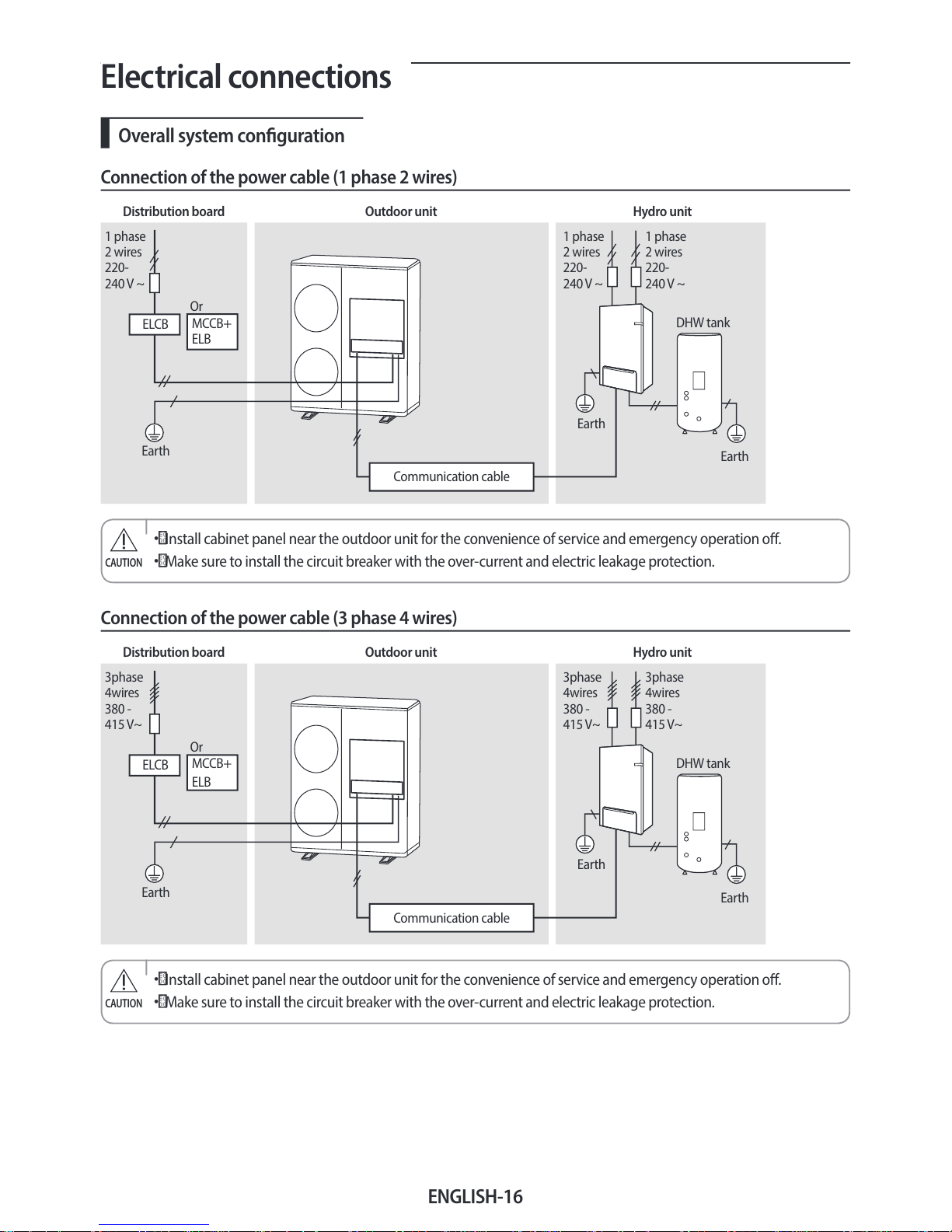
Connection of the power cable (1 phase 2 wires)
Distribution board Outdoor unit Hydro unit
1 phase
2 wires
220-
240V ~
Earth
Communication cable
ELCB
1 phase
2 wires
220-
240V ~
1 phase
2 wires
220-
240V ~
Earth
DHW tank
Earth
MCCB+
ELB
Or
• Install cabinet panel near the outdoor unit for the convenience of service and emergency operation o.
•
Make sure to install the circuit breaker with the over-current and electric leakage protection.
CAUTION
Connection of the power cable (3 phase 4 wires)
Distribution board Outdoor unit Hydro unit
3phase
4wires
380 -
415V~
Earth
Communication cable
ELCB
3phase
4wires
380 -
415V~
3phase
4wires
380 -
415V~
Earth
DHW tank
Earth
MCCB+
ELB
Or
• Install cabinet panel near the outdoor unit for the convenience of service and emergency operation o.
•
Make sure to install the circuit breaker with the over-current and electric leakage protection.
CAUTION
ENGLISH-17
02 INSTALLATION
Connecting the cable
Power cable specications
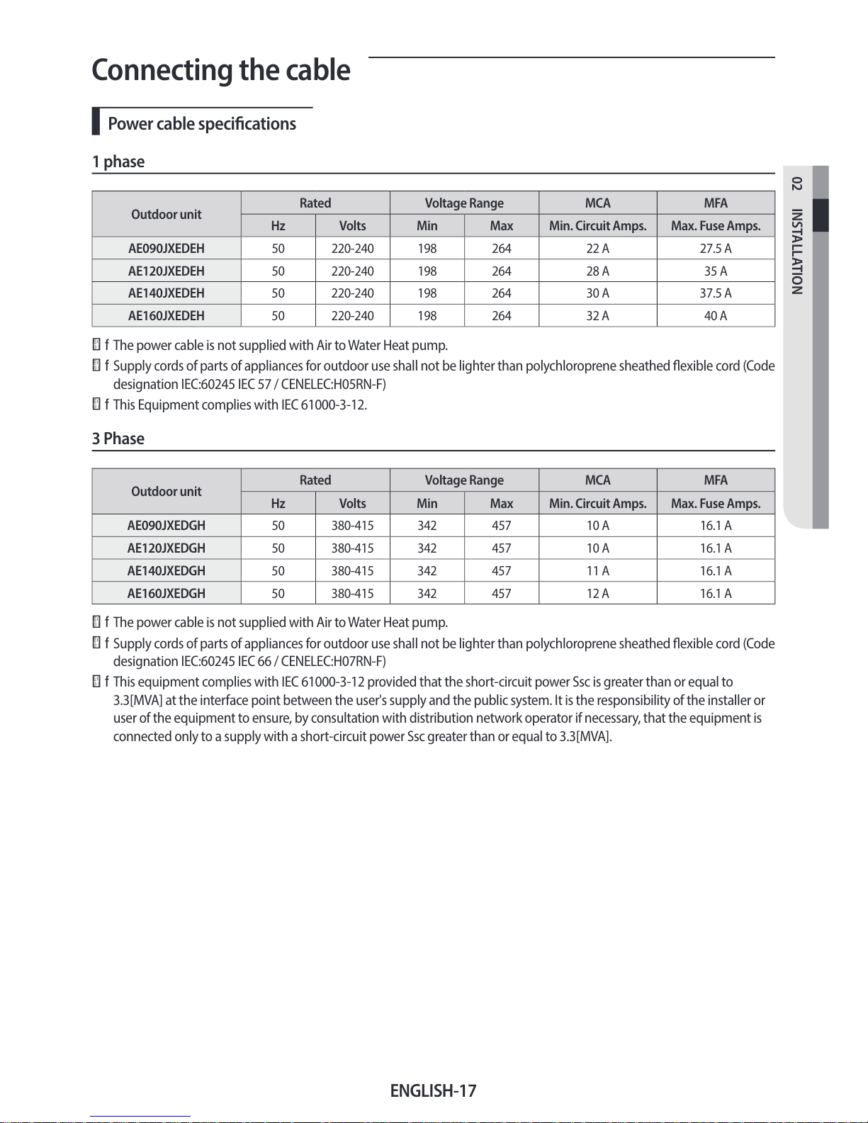
1 phase
Outdoor unit
Rated Voltage Range MCA MFA
Hz Volts Min Max Min. Circuit Amps. Max. Fuse Amps.
AE090JXEDEH 50 220-240 198 264 22 A 27.5 A
AE120JXEDEH 50 220-240 198 264 28 A 35 A
AE140JXEDEH 50 220-240 198 264 30 A 37.5 A
AE160JXEDEH 50 220-240 198 264 32 A 40 A
f The power cable is not supplied with Air to Water Heat pump.
f
Supply cords of parts of appliances for outdoor use shall not be lighter than polychloroprene sheathed exible cord (Code
designation IEC:60245 IEC 57 / CENELEC:H05RN-F)
f
This Equipment complies with IEC 61000-3-12.
3 Phase
Outdoor unit
Rated Voltage Range MCA MFA
Hz Volts Min Max Min. Circuit Amps. Max. Fuse Amps.
AE090JXEDGH 50 380-415 342 457 10 A 16.1 A
AE120JXEDGH 50 380-415 342 457 10 A 16.1 A
AE140JXEDGH 50 380-415 342 457 11 A 16.1 A
AE160JXEDGH 50 380-415 342 457 12 A 16.1 A
f The power cable is not supplied with Air to Water Heat pump.
f
Supply cords of parts of appliances for outdoor use shall not be lighter than polychloroprene sheathed exible cord (Code
designation IEC:60245 IEC 66 / CENELEC:H07RN-F)
f This equipment complies with IEC 61000-3-12 provided that the short-circuit power Ssc is greater than or equal to
3.3[MVA] at the interface point between the user's supply and the public system. It is the responsibility of the installer or
user of the equipment to ensure, by consultation with distribution network operator if necessary, that the equipment is
connected only to a supply with a short-circuit power Ssc greater than or equal to 3.3[MVA].
ENGLISH-18
Connecting the cable
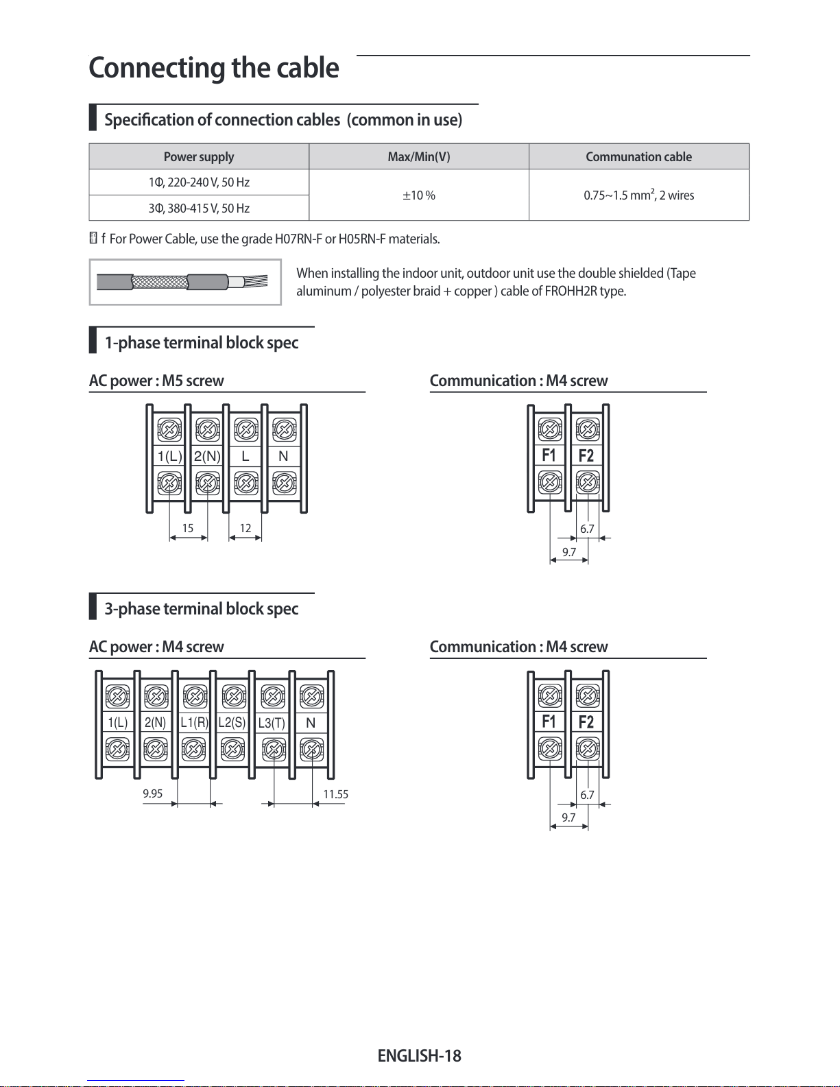
Specication of connection cables (common in use)
Power supply Max/Min(V) Communation cable
1Φ, 220-240V, 50Hz
±10% 0.75~1.5mm², 2 wires
3Φ, 380-415V, 50Hz
f For Power Cable, use the grade H07RN-F or H05RN-F materials.
When installing the indoor unit, outdoor unit use the double shielded (Tape
aluminum / polyester braid + copper ) cable of FROHH2R type.
1-phase terminal block spec
AC power : M5 screw Communication : M4 screw
N
L
2(N)
1(L)
15 12
6.7
9.7
3-phase terminal block spec
AC power : M4 screw Communication : M4 screw
N
L3(T)
L2(S)
L1(R)
2(N)
1(L)
9.95
11.55
6.7
9.7
ENGLISH-19
02 INSTALLATION
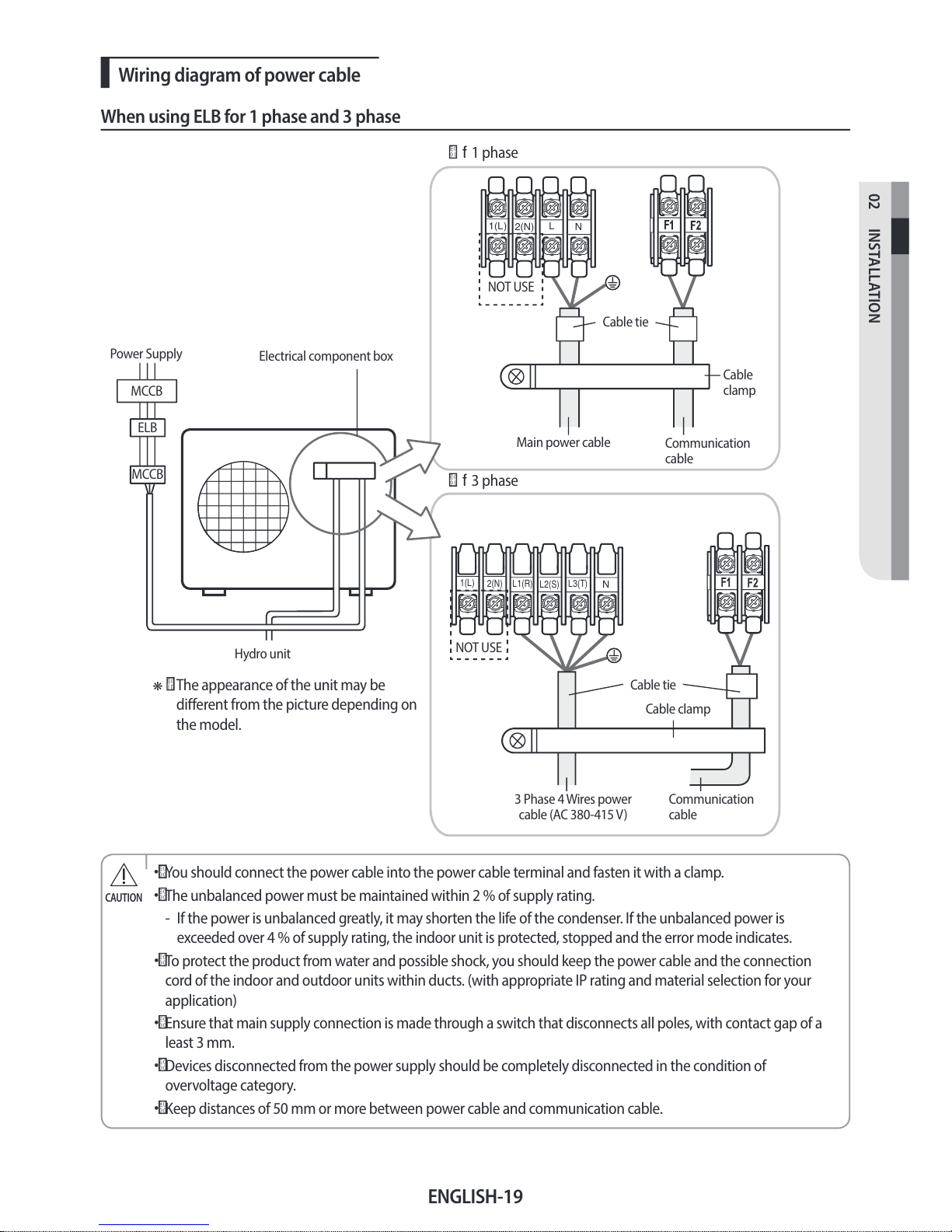
Wiring diagram of power cable
When using ELB for 1 phase and 3 phase
N
L3(T)
L2(S)
L1(R)
N
L
2(N)
1(L)
2(N)
1(L)
Power Supply
Electrical component box
MCCB
ELB
MCCB
Hydro unit
f 1 phase
f
3 phase
Communication
cable
Main power cable
Cable
clamp
❋ The appearance of the unit may be
dierent from the picture depending on
the model.
Cable tie
Cable tie
Cable clamp
Communication
cable
3 Phase 4 Wires power
cable (AC 380-415V)
NOT USE
NOT USE
• You should connect the power cable into the power cable terminal and fasten it with a clamp.
•
The unbalanced power must be maintained within 2% of supply rating.
- If the power is unbalanced greatly, it may shorten the life of the condenser. If the unbalanced power is
exceeded over 4% of supply rating, the indoor unit is protected, stopped and the error mode indicates.
•
To protect the product from water and possible shock, you should keep the power cable and the connection
cord of the indoor and outdoor units within ducts. (with appropriate IP rating and material selection for your
application)
•
Ensure that main supply connection is made through a switch that disconnects all poles, with contact gap of a
least 3 mm.
•
Devices disconnected from the power supply should be completely disconnected in the condition of
overvoltage category.
• Keep distances of 50mm or more between power cable and communication cable.
CAUTION
ENGLISH-20
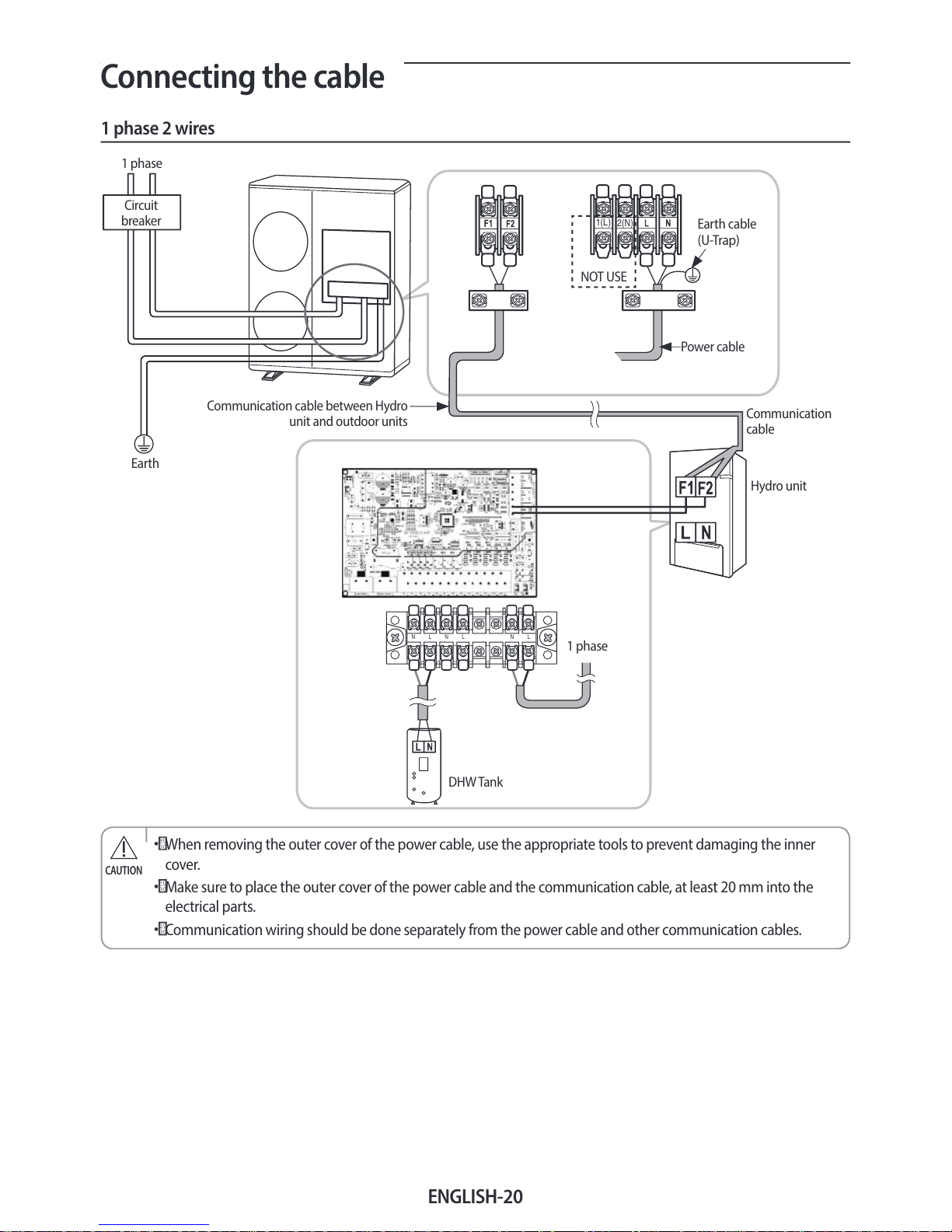
Connecting the cable
1 phase 2 wires
N L N L N L
2(N)
1(L)
1 phase
Earth
Communication cable between Hydro
unit and outdoor units
Power cable
Earth cable
(U-Trap)
1 phase
DHW Tank
Hydro unit
Communication
cable
Circuit
breaker
NOT USE
• When removing the outer cover of the power cable, use the appropriate tools to prevent damaging the inner
cover.
• Make sure to place the outer cover of the power cable and the communication cable, at least 20mm into the
electrical parts.
•
Communication wiring should be done separately from the power cable and other communication cables.
CAUTION
ENGLISH-21
02 INSTALLATION
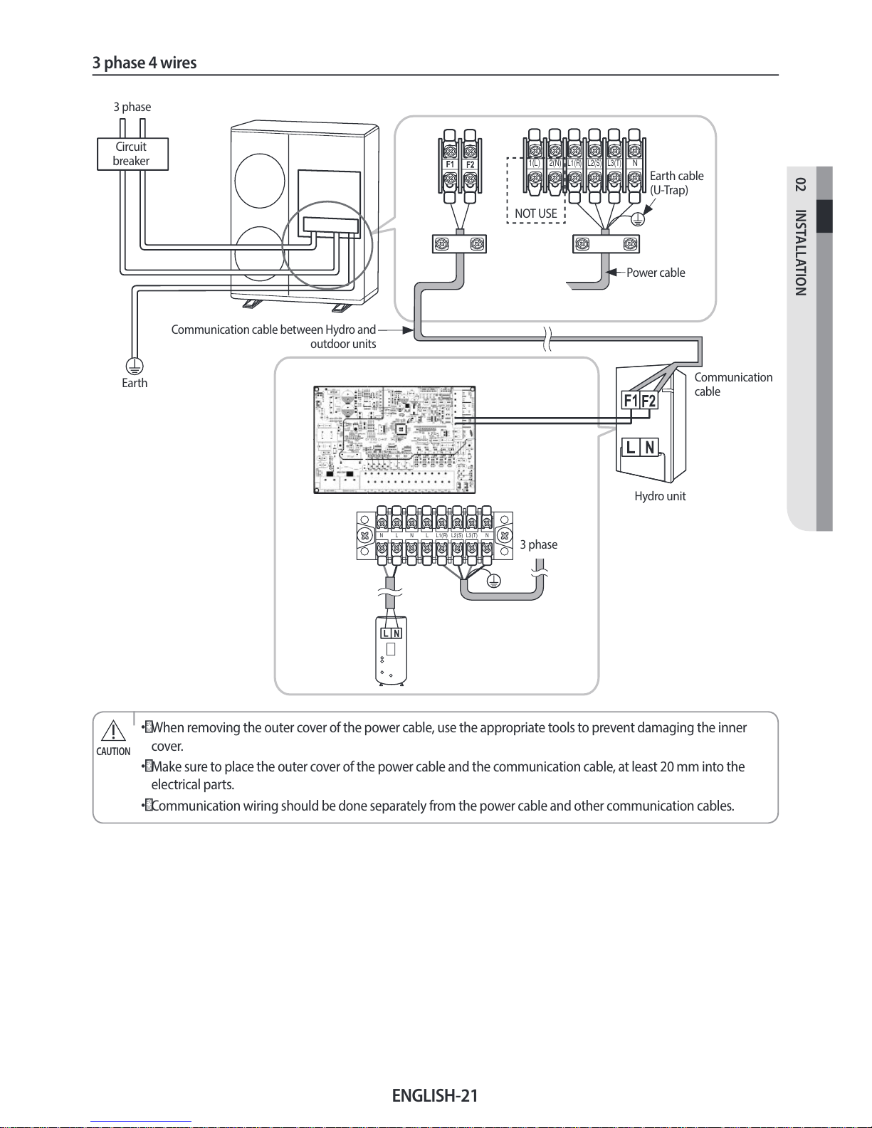
3 phase 4 wires
N L N L L1(R) L2(S) L3(T) N
L1(R) L2(S) L3(T)
N
2(N)
1(L)
3 phase
Earth
Communication cable between Hydro and
outdoor units
Power cable
Earth cable
(U-Trap)
3 phase
Hydro unit
Communication
cable
Circuit
breaker
NOT USE
• When removing the outer cover of the power cable, use the appropriate tools to prevent damaging the inner
cover.
•
Make sure to place the outer cover of the power cable and the communication cable, at least 20mm into the
electrical parts.
•
Communication wiring should be done separately from the power cable and other communication cables.
CAUTION
ENGLISH-22
Connecting the cable
Connecting the power terminal
f Connect the cables to the terminal board using the compressed ring terminal.
f
Connect the rated cables only.
f
Connect using a wrench which is able to apply the rated torque to the screws.
f
If the terminal is loose, re may occur caused by arc. If the terminal is connected too rmly, the terminal may be
damaged.
Tightening Torque (kgf.cm)
M4 12~18
M5 20~30
Installing the earth wire
f Earthing must be done by your installation specialist for your safety.
f
Use the earth wire by referring to the specication of the electric cable for the outdoor unit.
Earthing the power cable
f The standard of earthing may vary according to the rated voltage and installation place of the Air to Water Heat Pump.
f
Earth the power cable according to the following.
Installation place
Power condition
High humidity Average humidity Low humidity
Electrical potential of lower than 150V Perform the earthing work 3.
Note 1)
Perform the earthing work 3 if
possible for your safety.
Note 1)
Electrical potential of higher than 150V
Must perform the earthing work 3.
Note 1)
(In case of installing circuit breaker)
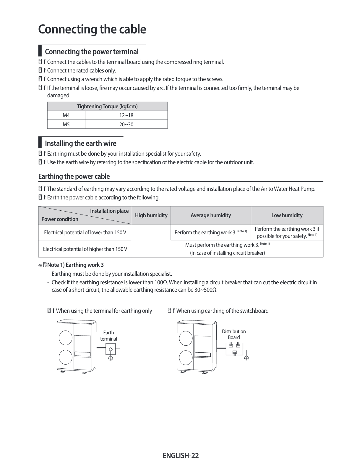
❋ Note 1) Earthing work 3
- Earthing must be done by your installation specialist.
- Check if the earthing resistance is lower than 100Ω. When installing a circuit breaker that can cut the electric circuit in
case of a short circuit, the allowable earthing resistance can be 30~500Ω.
f
When using the terminal for earthing only f When using earthing of the switchboard
Earth
terminal
Distribution
Board
ENGLISH-23
02 INSTALLATION
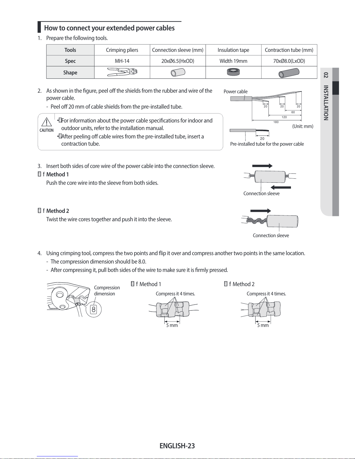
How to connect your extended power cables
1. Prepare the following tools.
Tools Crimping pliers Connection sleeve (mm) Insulation tape Contraction tube (mm)
Spec MH-14 20xØ6.5(HxOD) Width 19mm 70xØ8.0(LxOD)
Shape
2. As shown in the gure, peel o the shields from the rubber and wire of the
power cable.
- Peel o 20 mm of cable shields from the pre-installed tube.
• For information about the power cable specications for indoor and
outdoor units, refer to the installation manual.
•
After peeling o cable wires from the pre-installed tube, insert a
contraction tube.
CAUTION
20
Pre-installed tube for the power cable
(Unit: mm)
12 0
60
202020
18 0
Power cable
3. Insert both sides of core wire of the power cable into the connection sleeve.
f
Method 1
Push the core wire into the sleeve from both sides.
Connection sleeve
f Method 2
Twist the wire cores together and push it into the sleeve.
Connection sleeve
4. Using crimping tool, compress the two points and ip it over and compress another two points in the same location.
- The compression dimension should be 8.0.
- After compressing it, pull both sides of the wire to make sure it is rmly pressed.
Compression
dimension
f Method 1
Compress it 4 times.
5 mm
f Method 2
Compress it 4 times.
5 mm
 Loading...