

Samsung AE090MNYDEH, AE090MNYDGH, AE160MNYDEH, AE160MNYDGH Installation Manual

Air to Water Heat Pump -TDM PLUS Hydro Unit
Installation manual
AE090MNYDEH / AE090MNYDGH / AE160MNYDEH / AE160MNYDGH
• Thank you for purchasing this Samsung air conditioner.
• Before operating this unit, please read this manual carefully and retain it for future
reference.

2
English
Contents
PREPARATION 3
Safety precautions 3
Product Specifications 5
Typical application examples 9
Main components 11
Functional diagram 12
Dimensional drawing 13
INSTALLATION 14
Installing the unit 14
Pipe work 16
Wiring work 23
Self-test mode of wired remote controller 35
OTHERS 37
Troubleshooting 37
DHW tank 40
Mixing Valve 47
Concrete curing function 51
Installation option setting 53
How to connect your extended power cables 55
COMMISSION REGULATION (EU) No 813/2013 ᶦ⁾ 58
COMMISSION DELEGATED REGULATION (EU) No 811/2013
i)
83

3
English
PREPARATION
All materials supplied to this manual are indispensable for the
safety of equipment.
Users shall establish appropriate safety and health practices
and determine the applicability of regulatory limitation based
on following descriptions prior to use.
WARNING
• Always disconnect the air to water heat pump from the
power supply before servicing it or accessing its internal
components.
• Verify that installation and testing operations are
performed by qualified personnel.
• Verify that the air to water heat pump is not installed in an
easily accessible area.
GENERAL INFORMATION
WARNING
• Carefully read the content of this manual before installing the
air to water heat pump and store the manual in a safe place in
order to be able to use it as reference after installation.
• For maximum safety, installers shall always carefully read the
following warnings.
• Store the user and installation manual in a safe location and
remember to hand it over to the new owner if the air to water
heat pump is sold or transferred.
• This manual explains how to install SAMSUNG TDM Plus
product. The use of other types of units with different control
systems may damage the units and invalidate the warranty.
The manufacturer shall not be responsible for damages arising
from the use of non compliant units.
• The manufacturer shall not be responsible for damage
originating from unauthorized changes or the improper
connection of electric and hydraulic lines. Failure to comply
with these instructions or to comply with the requirements set
forth in the “Operating limits” table, included in the manual,
shall immediately invalidate the warranty.
• Do not use the units if damaged. If problems occur, switch the
unit off and disconnect it from the power supply.
• In order to prevent electric shocks, fires or injuries, always stop
the unit, disable the protection switch and contact SAMSUNG’s
technical support if the unit produces smoke, if the power cable
is hot or damaged or if the unit is very noisy.
• Always remember to inspect the unit, electric connections,
refrigerant tubes and protections regularly. These operations
should be performed by qualified personnel only.
• The unit contains moving parts, which should always be kept
out of the reach of children.
• Do not attempt to repair, move, alter or reinstall the unit. If
performed by unauthorized personnel, these operations may
cause electric shocks or fires.
• Do not place containers with liquids or other objects on the
unit.
• All the materials used for the manufacture and packaging of
the air to water heat pump are recyclable.
• The packing material and exhaust batteries of the remote
control(optional) must be disposed of in accordance with
current laws.
• The air to water heat pump contains a refrigerant must be
disposed in authorized center or returned to retailer as special
wastes.
• Do not disassemble and alter the heater at your own discretion.
INSTALLING THE UNIT
IMPORTANT: When installing the unit, always remember to
connect first the refrigerant tubes, then the electrical lines.
Always disassemble the electric lines before the refrigerant
tubes.
• Upon receipt, inspect the product to verify that it has not been
damaged during transport. If the product appears damaged,
DO NOT INSTALL it and immediately report the damage to the
carrier or retailer (if the installer or the authorized technician
has collected the material from the retailer.)
• After completing the installation, always carry out a functional
test and provide the instructions on how to operate the air to
water heat pump to the user.
• Do not use the air to water heat pump in environments with
hazardous substances or close to equipment that release free
flames to avoid the occurrence of fires, explosions or injuries.
Safety precautions

4
Safety precautions
English
PREPARATION
POWER SUPPLY LINE, FUSE OR CIRCUIT
BREAKER
• Always make sure that the power supply is compliant with
current safety standards. Always install the air to water heat
pump in compliance with current local safety standards.
• Always verify that a suitable grounding connection is
available.
• Verify that the voltage and frequency of the power supply
comply with the specifications and that the installed power
is sufficient to ensure the operation of any other domestic
appliance connected to the same electric lines.
• Always verify that the cut-off and protection switches are
suitably dimensioned.
• Verify that the air to water heat pump is connected to the
power supply in accordance with the instructions provided
in the wiring diagram included in the manual.
• Always verify that electric connections (cable entry, section
of leads, protections…) are compliant with the electric
specifications and with the instructions provided in the
wiring scheme. Always verify that all connections comply
with the standards applicable to the installation of air to
water heat pumps.
• Be sure not to perform power cable modification, extension
wiring, and multiple wire connection.
– It may cause electric shock or fire due to poor
connection, poor insulation, or current limit override.
– When extension wiring is required due to power line
damage, refer to "How to connect your extended power
cables" in the installation manual.
CAUTION
• Make sure that you earth the cables.
– Do not connect the earth wire to the gas pipe, water
pipe, lighting rod or telephone wire. If earthing is not
complete, electric shock or fire may occur.
• Install the circuit breaker.
– If the circuit breaker is not installed, electric shock or
fire may occur.
• Make sure that the condensed water dripping from the
drain hose runs out properly and safely.
• Install the power cable and communication cable of the
indoor and outdoor unit at least 1m away from the electric
appliance.
5
English
PREPARATION
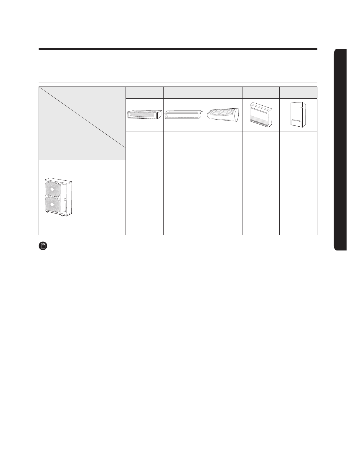
Product compatibility
Indoor unit
Outdoor unit
Slim Duct MSP Duct RAC Console Hydro Unit
2.2~5.6kW 7.1~9kW 2 . 2~7.1 kW 2.2~5.6kW 9/16kW
Classification Features
AE022MNLDEH
AE028MNLDEH
AE036MNLDEH
AE056MNLDEH
AE071MNMPEH
AE090MNMPEH
AE022MNADEH
AE028MNADEH
AE036MNADEH
AE056MNADEH
AE071MNADEH
AE022MNJDEH
AE028MNJDEH
AE036MNJDEH
AE056MNJDEH
AE090MNYDEH
AE160MNYDEH
AE090MNYDGH
AE160MNYDGH
- Heat pump for
heating and hot
water system
[Eco Heating Full
System]
- Outdoor unit:
4.4/6.6/9/12/16 kW
- Long pipe reliability:
75m
NOTE
• AE∗∗∗MXTP∗H and above EHS TDM Indoor units are applicable for EHS products only.
They are not compatible with EHS Split Hydro unit, CAC, DVM and FJM products.
• A2W: Air to Water, A2A: Air to Air
Product Specifications
6
Product Specifications
English
PREPARATION
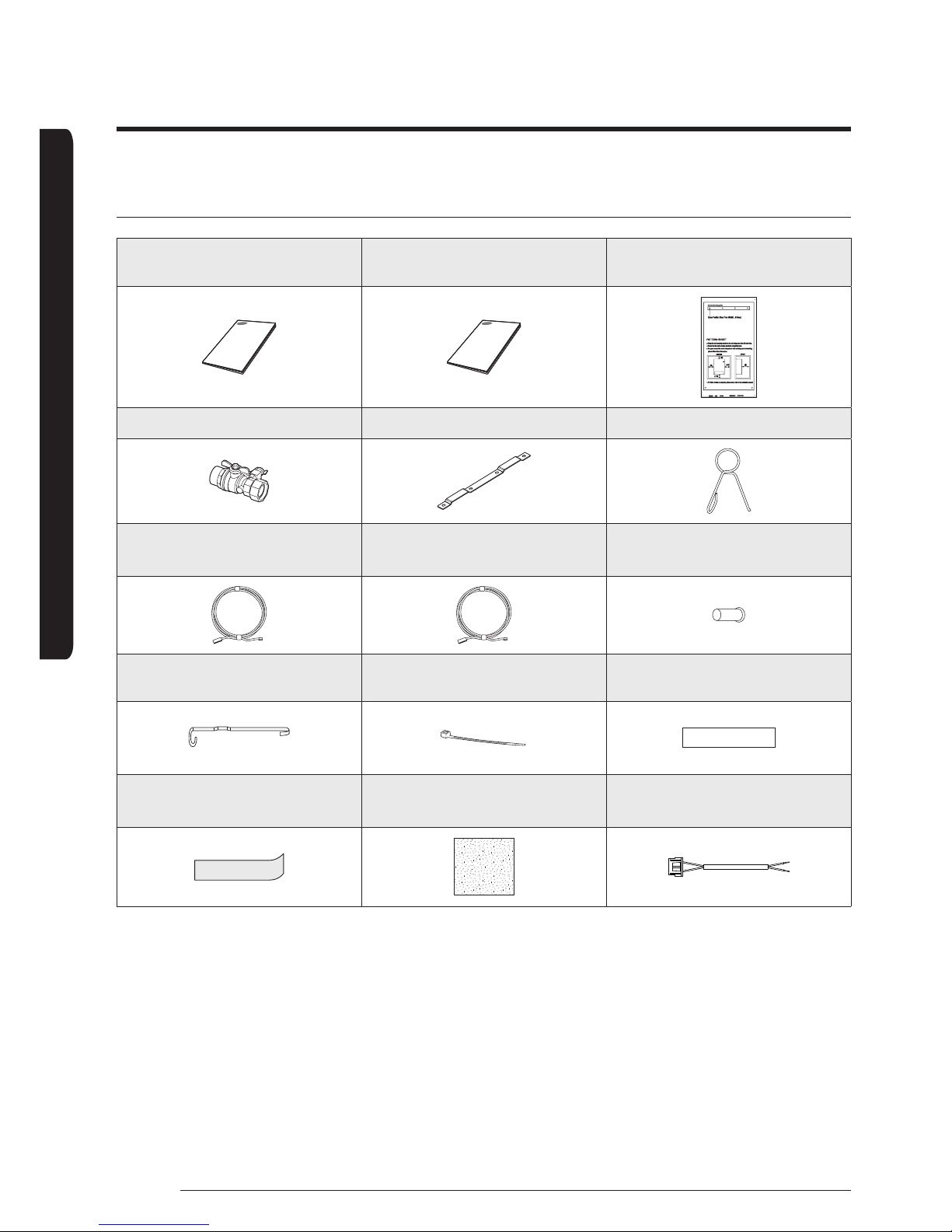
Accessories
Installation Manual(1) User Manual(1) Pattern Sheet(1)
Service Valve(2) Wall Mounting Bracket(1) Ring band (1)
Temperature Sensor for DHW Tank
(1x15m,YEL) (1)
Temperature Sensor for Mixing
Valve (1x15m, BLU) (1)
Sensor holder of mixing valve
(ID Ø6.8mm) (1)
Sensor clip for mixing Valve Sensor
(1)
Cable-tie for mixing valve (4) Aluminum tape for mixing valve (1)
Rubber tape for mixing Valve Sensor
(1)
Insulator for mixing valve (1)
Connector Wire -Smart Grid
(1x2m, RED) (1)
7
English
PREPARATION
Specications
Type Unit AE090MNYDEH AE090MNYDGH AE160MNYDEH AE160MNYDGH
Power Source
V/Hz
1ø, 220-240V~,
50Hz
3ø, 380-415V~,
50Hz
1ø, 220-240V~,
50Hz
3ø, 380-415V~,
50Hz
Operation Range
[Water]
Cooling
°C 5~25 5~25 5~25 5~25
Heating
°C 15~55 15~55 15~55 15~55
Dimension
(WxHxD)
Net
mm 850 x 510 x 315 850 x 510 x 315 850 x 510 x 315 850 x 510 x 315
Weight Net
kg 45.5 46.5 46.5 46.5
Connecting Pipe
[Refrigerant]
Liquid
Inch 1/4 1/4 3/8 3/8
Gas
Inch 5/8 5/8 5/8 5/8
Service Valve
Connecting Pipe
[Water]
Inlet
Inch BSPP male 1 1/4 BSPP male 1 1/4 BSPP male 1 1/4 BSPP male 1 1/4
Outlet
Inch BSPP male 1 1/4 BSPP male 1 1/4 BSPP male 1 1/4 BSPP male 1 1/4
Water Pump
Max Vol
Flow
m3/h 3.5 3.5 5.0 5.0
Electric Heater
Input
power
W 4,000 6,000 6,000 6,000
Flow Switch Set Point
LPM 7±1.5 7±1.5 12±1.5 12±1.5
Expansion Vessel Volume
Liter 8.0 8.0 8.0 8.0
Pressure relief
valve
Size
Inch BSPP male 1/2 BSPP male 1/2 BSPP male 1/2 BSPP male 1/2
Relief
Pressure
bar 2.9 2.9 2.9 2.9
Air- vent Valve Size
inch BSPP male 3/8 BSPP male 3/8 BSPP male 3/8 BSPP male 3/8
Operating
Outdoor Temp.
Range
Heating
°C
-25 ~ 35 -25 ~ 35 -25 ~ 35 -25 ~ 35
Cooling
10 ~ 46 10 ~ 46 10 ~ 46 10 ~ 46
DHW
Water
-25 ~ 43 -25 ~ 43 -25 ~ 43 -25 ~ 43
∗ Heat pump operating range of DHW : -25 ~ 35 °C
∗ At the temperature -25°C ~ -20°C, operation is available but capacity cannot be guaranteed.
8
Product Specifications
English
PREPARATION
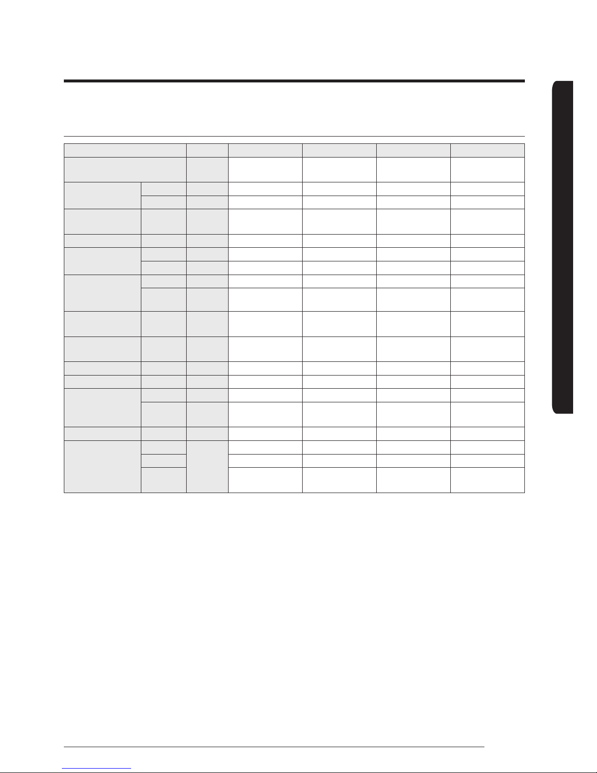
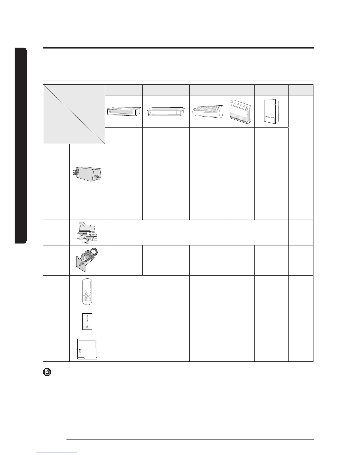
Subsidiary materials compatibility
Indoor unit
Subsidiary materials
Slim Duct MSP Duct RAC Console Hydro Unit Remark
2.2~5.6kW 7.1~9kW 2. 2~ 7.1kW 2.2~5.6kW 9/16kW
EEV Kit
EEV Kit for 1/2/3
room
- -
MEV-E24SA
MEV-E32SA
MXD-E24K132A
MXD-E24K200A
MXD-E24K232A
MXD-E24K300A
MXD-E32K200A
MXD-E32K224A
MXD-E32K300A
- - Requisite
Y-joint
MXJ-YA1509M
(≤15.0kW and below)
Requisite
Drain
Pump
MDP-
E075SEE3D
(Option,
Internal Type)
MDP-G075SP
(Option, External Type)
MDP-G075SQ
(Option, Internal Type)
- - -
Wireless
remote
controller
MR-EH00
(Option)
MR-EH00
(Included)
- -
Remote
controller
receive kit
MRK-A10N
(Option)
- - -
Wired
remote
controller
MWR-WE10N
(Option)
- -
MWR-
WW00N
(Included)
NOTE
• Subsidiary materials are compatible with DVM products.
• EEV KIT : Required installation. It is not included inside of product. Install distribution kit for 1, 2 or 3 indoor on the ceiling or
outdoor area.
• A2W: Air to Water, A2A: Air to Air
9
English
PREPARATION
Typical application examples
CAUTION
• The application examples given below are for illustration purposes only.
• When the SAMSUNG Air-to-Water Heat Pump system is used in series with another heat source (e.g. gas boiler), ensure that
the return water temperature not exceed 55°C.
• The unit is only to be used in a closed water system. Application in an open water circuit can lead to excessive corrosion of the
water piping.
• SAMSUNG can not be responsible put responsible for incorrect installations in the water system. Make sure that the boiler,
radiators, convectors, solar collectors, UFHs, FCUs, additional pumps, pipes, and controls in the water system are in accordance
with relevant local laws and regulations under the installer’s responsibility.
• SAMSUNG shall not be held liable for any damage resulting from not observing this rule.
• SAMSUNG do not provide specific water system components such as Pressure relief valve, Air vent valve, buffer tank and etc.
Installers and end-users shall consider how to install the above designated components in overall water system depending on
the installation conditions. If the components are not installed in appropriate location, the water system can not be operated
as designed.
∗ The below examples are for illustration purposes only.
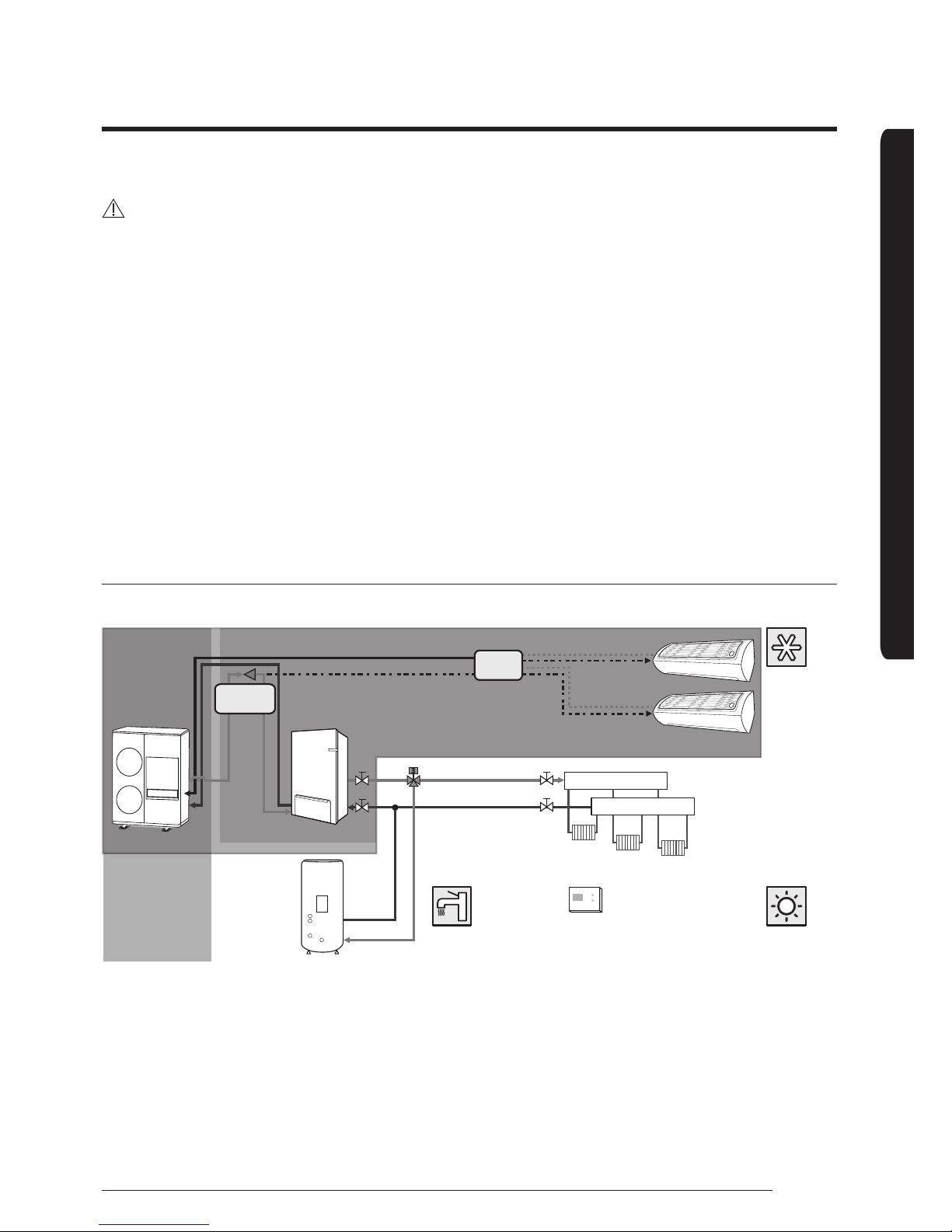
Application 1 : TDM(Time Division Multi)
Outdoor Indoor
Outdoor unit
DHW Tank
Hydro-unit
RAC
Space
Cooling
Space
Heating
Room Controller
Supply Header
Return Header
Radiator or FCU
Water Heating
Samsung Supply Range
EEV Kit
Y joint
10
Typical application examples
English
PREPARATION
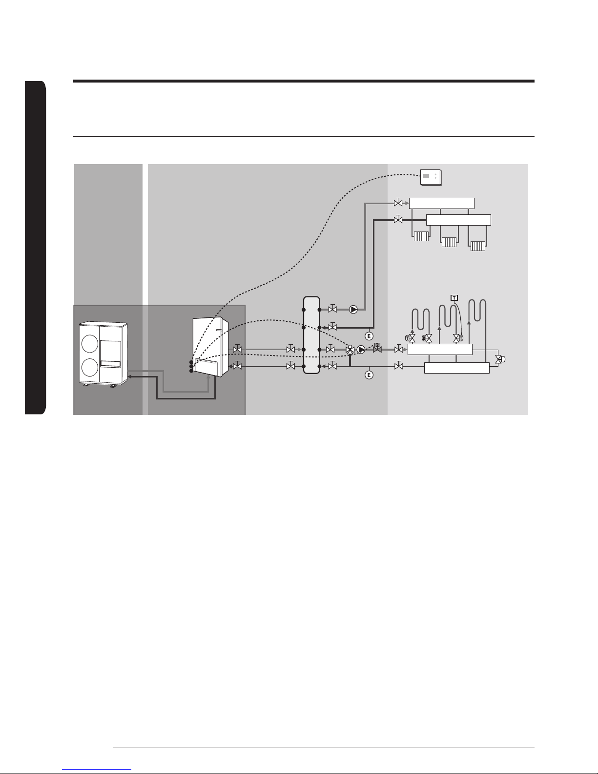
Application 2 : Space heating
Samsung Supply Range
Outdoor unit
Hydro-unit
Mixing Tank
Under-Floor Heating Coils
[Application #1]
Zone Thermostat & 2way Valve
[Application #2]
Thermostatic &
Balancing Valves
[Application #4]
Differential Pressure bypass Valve
[Application #3]
Room Thermosat &
Actuators
Supply Header
Supply Header
Return Header
Return Header
Bypass
valve
Room
Controller
Load Pump #1
Load Pump #2
40 °C
45 °C
Outdoor
Indoor
Radiators or Convectors
11
English
PREPARATION
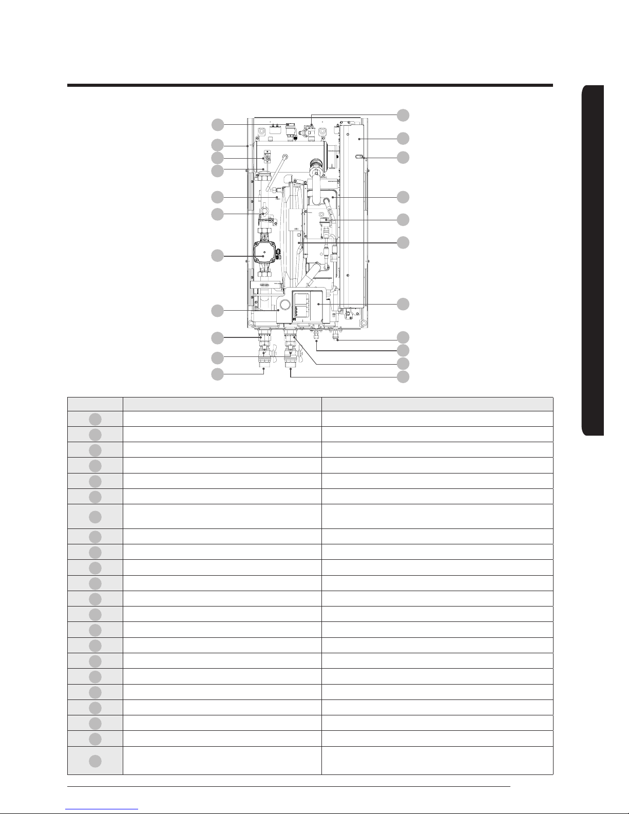
Main components
21
20
19
18
22
17
16
15
14
13
12
01
02
03
04
05
06
07
08
09
10
11
No. Name Note
01
Air vent 3/8” BSPP male 3/8”
02
Backup heater thermal fuse Thermal cut out 94°C (+0, -6°C)
03
Backup heater thermostat Disc. 65°C ±4°C
04
Backup Heater Element Incoloy 800, 4/6kW, 230V AC 50Hz
05
Drain Hose
06
Flow switch 9kW : 7LPM ± 1.5LPM / 16kW : 12LPM ± 1.5LPM
07
Water pump
AE090MNYD*H : 1P-230V-50Hz,26LPM x 65kPa
AE0160MNYD*H : 1P-230V-50/60Hz,46LPM x 60kPa
08
Manometer ø48, 0~4 bar
09
Water outlet pipe BSPP male 1 1/4"
10
Drain valves
11
Service valve (L) BSPP male, 1-1/4”
12
Service valve (R) BSPP male, 1-1/4”
13
Water inlet pipe BSPP male 1 1/4"
14
Refrigerant pipe 9kW : Ø6.35(1/4") / 16kW : Ø9.52(3/8")
15
Refrigerant pipe ø15.88 (5/8”)
16
Wire for controller length 15m
17
Expansion Vessel 8 Liter, Pre-charge gas : 0.1MPa, N2, BSPP male, 3/8”
18
Plate heat exchanger
19
LED display
20
Control box
21
Pressure relief valve 0.3MPa, BSPP 1/2”
22
Expansion valve
AE090MNYD∗H : EDM Type, DPF(O)3.2C
AE0160MNYD∗H : EDM Type, DPF(O)4.0C
12
English
PREPARATION
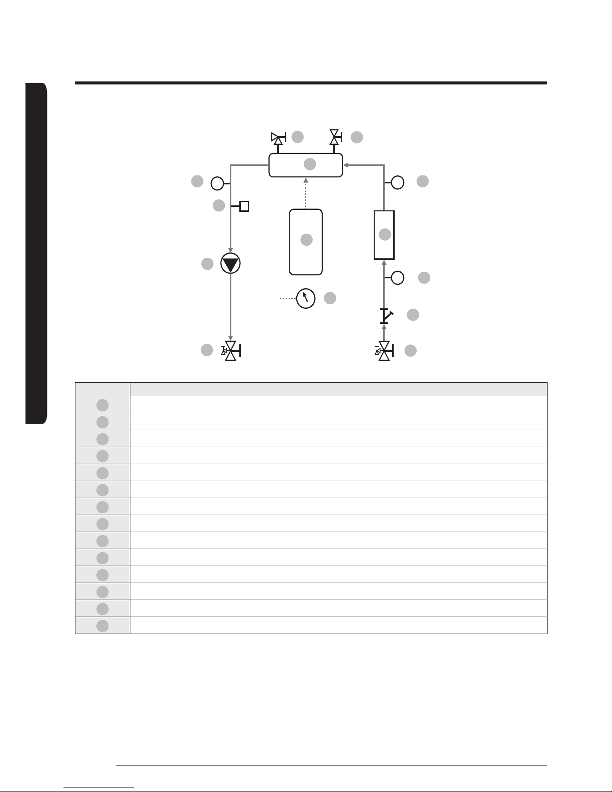
Functional diagram
Tw3
Tw2
Tw1
14 13
12
01
02
03
04
05
06
07
08
09
10
11
No. Note
01
Service valve(R)
02
Strainer
03
Flow switch
04
Heat exchanger
05
Backup heater
06
Pressure relief valve
07
Air-vent valve
08
Variable Speed water pump
09
Expansion tank
10
Manometer
11
Service valve(L)
12
Water temp. sensor 1
13
Water temp. sensor 2
14
Water temp. sensor 3

13
English
PREPARATION
Dimensional drawing
510
850
125
104 103.7 78.5 131.7
490
22
39.2
314.6
Gas pipe (O.D.) Liquid pipe (O.D.) Water Inlet Water Outlet
Indoor unit 15.88mm (5/8inch)
9kW : 6.35mm (1/4inch)
16kW : 9.52mm (3/8inch)
BSPP male 1 1/4" BSPP male 1 1/4"
14
INSTALLATION
English
Installing the unit
Installation of the indoor unit
The indoor unit should be installed indoors and meet the following conditions.
• Installation site should be sheltered from frost.
• In area with suitable space for servicing.
• A place with adequate ventilation.
• Where there is no risk of leakage of flammable gases.
• There is a provision for condensate drain and pressure relief valve blow-off.
• The wall for installation is a flat, vertical and non-combustible wall, capable of supporting the operation weight of the unit.
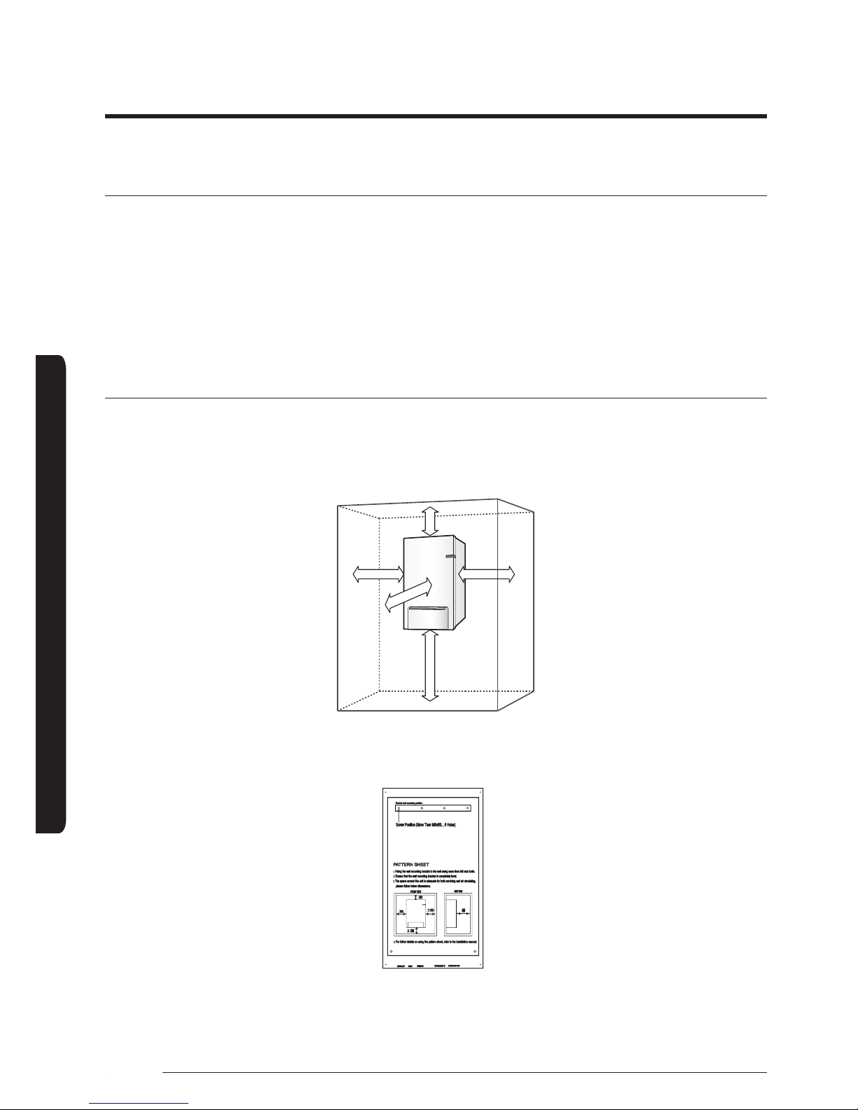
Installation space
• Ensure to leave the appropriate space as indicated in the drawing.
• Installation site should be secured with adequate ventilation so that the components of hydro unit will not be damaged from
overheating.
(Unit : mm )
300
500
200≥1200
≥350
• Before installing the indoor unit, fix the pattern sheet on the wall. This sheet has a function to take correct position for the wall
mounting bracket and screws.
Pattern Sheet
15
INSTALLATION
English
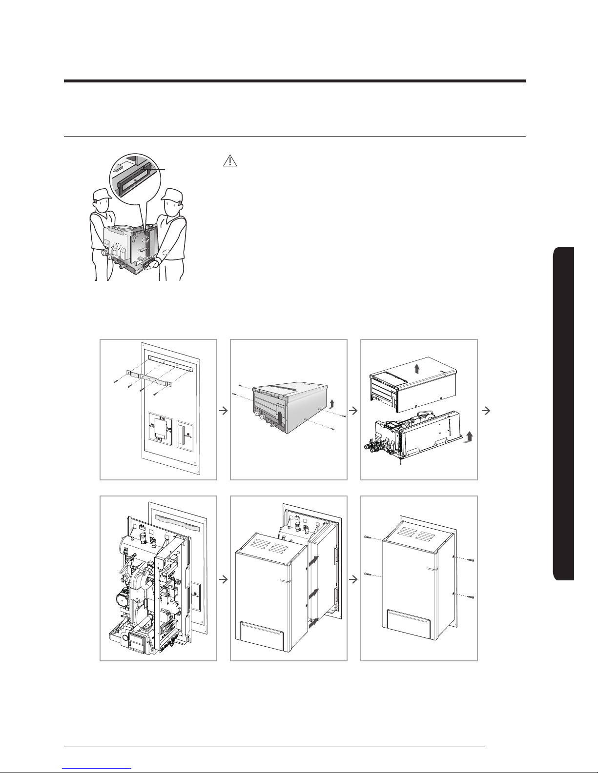
Mounting the indoor unit
Handle
CAUTION
• A minimum of two people should lift the unit by the handles and not by the
drain pan or pipe work.
• Drill 6 holes from the pattern sheet for fixing the wall bracket and unit. After completing holes, detach the pattern sheet.
• Fix the wall-mount-bracket to the wall using appropriate plugs and screws(Use over M8 6 screws).
• Hang the indoor unit on a wall-mount-bracket and fix a front cabinet on the unit by using 4 screws.
• Fix screw through base panel of the unit.
16
INSTALLATION
English
Refrigerant pipe work
For all guide lines, specifications regarding refrigerant pipe work between the indoor unit and the outdoor unit, please follow the
outdoor unit installation manual.
Gas pipe
(O.D.)
Liquid pipe (O.D.)
Tightening
Torque
Final Torque
Indoor unit
15.88mm
(5/8 inch)
9kW : 6.35mm (1/4 inch)
16kW : 9.52mm (3/8 inch)
400kg∙cm 450kg∙cm
Outdoor unit
15.88mm
(5/8 inch)
Φ9.52mm(3/8 inch) 700kg∙cm 750kg∙cm
CAUTION
• When connecting the refrigerant pipes, always use 2 wrenches/spanners for tightening or loosening nuts. If not, piping
connections can be damaged.
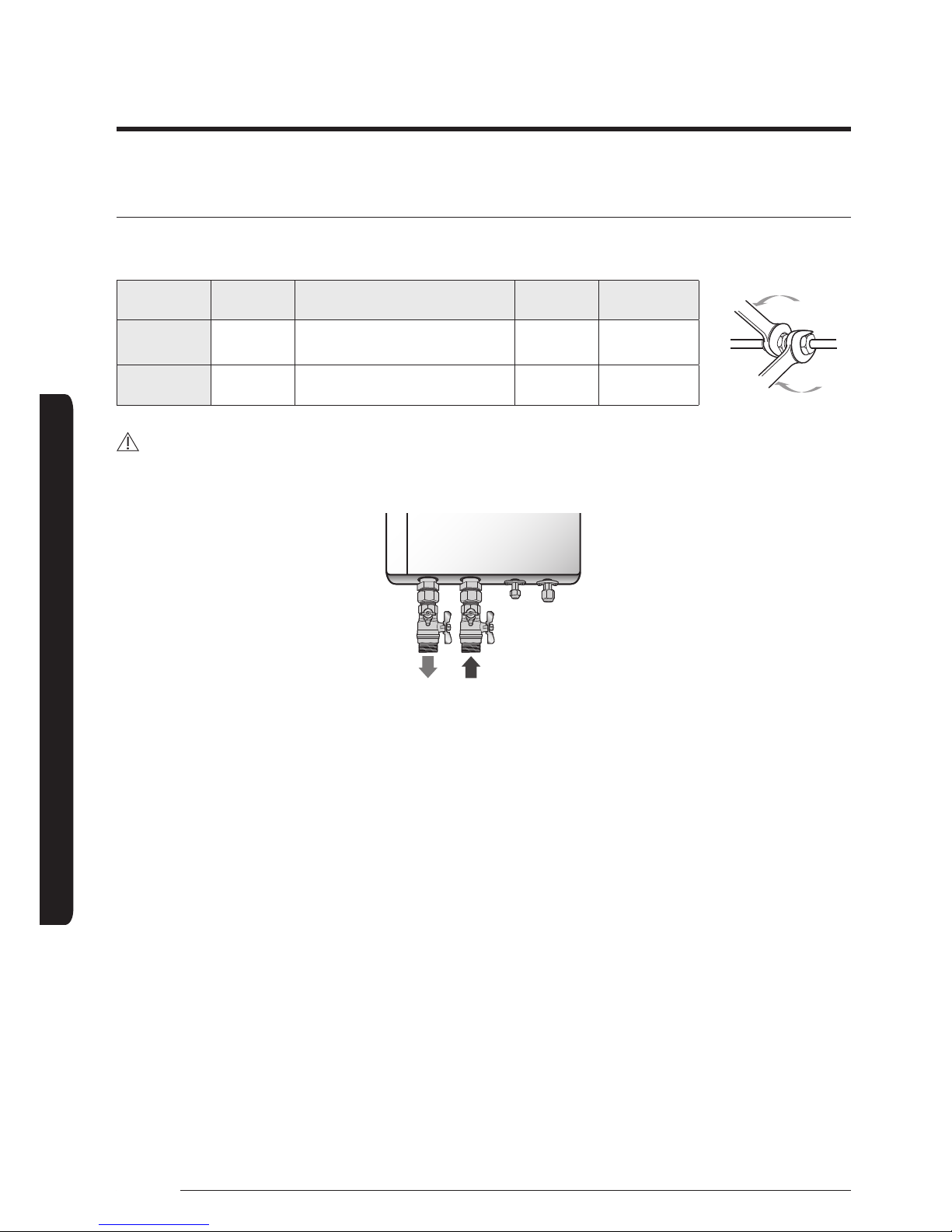
WATER
OUTLET
WATER
INLET
Liquid
pipe
Gas
pipe
Pipe work
17
INSTALLATION
English
Water pipe work
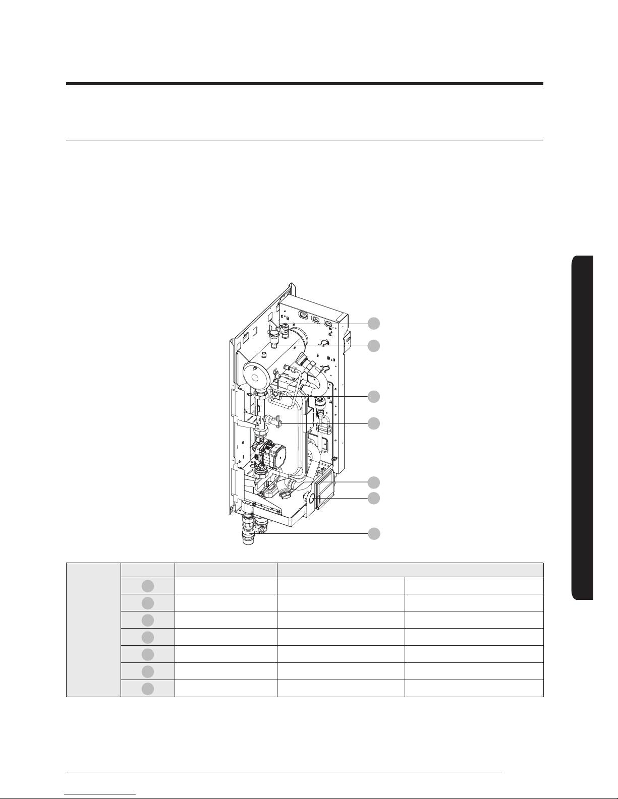
The hydro unit is equipped with components listed on the table below.
The hot and cold water supply connections are clearly marked on the unit with labels. And service valves are provided.
Whole water plumbing system including Hydro unit shall be installed by a qualified technician and must comply with all relevant
European and national regulations.
• Allowable water pressure of hydro unit is maximum 3.0 bar.
• 2 service valves are provided with the Hydro unit. To facilitate service and maintenance work, install R-Type service valve at the
water inlet of the hydro unit and L-Type service valve at the water outlet of the hydro unit.
• An air-vent valve is integrated on the hydro unit. Please check that air-vent valve is not overtightened so the air-vent valve can
release any air out of the system during system operation.
01
02
03
04
05
06
07
Hydro unit
No. Name Tightening Torque
01
1.25” BSPP 350 ~ 380 kgf•cm 34 ~ 37 N•m
02
3/8” BSPP 120 ~ 150 kgf•cm 12 ~ 15 N•m
03
Pressure relief valve 120 ~ 150 kgf•cm 12 ~ 15 N•m
04
Air-vent valve 120 ~ 150 kgf•cm 12 ~ 15 N•m
05
Manometer 92~ 102 kgf•cm 9 ~ 10 N•m
06
Flow switch 72 ~ 82 kgf•cm 7 ~ 8 N•m
07
Strainer 350 ~ 380 kgf•cm 34 ~ 37 N•m
18
Pipe work
INSTALLATION
English
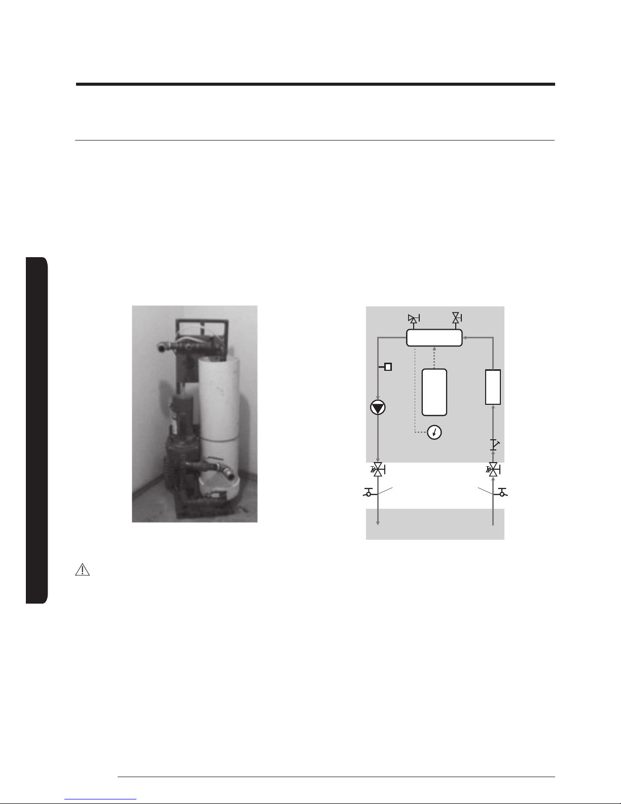
Flushing and air-purging
When filling water, the following start-up procedure should be followed.
1 All system components and pipes must be tested for the presence of leaks.
2 Preparation of a make-up water assembly or Flushing unit is recommended for installation and service.
3 3. Before connecting pipes to the hydro unit, Flush water pipes clean to remove contaminants during 1 hours using a flushing
unit or tap water pressure if it is adequate (at 2 to 3 bar)
4 Fill water into the hydro unit by opening service valves.
5 Purge the air. (Fill with a flushing unit with sufficient capacity: avoid aerating the water)
6 Circulate for long enough to ensure that all air has been bled from the complete water piping system.
After installations, Commissioning should be performed by qualified representatives.
Unless flushing and air-purging works are performed adequately, it might result in malfunctions.
Flushing unit (or purging cart)
Hydro unit
Water Out
Strainer
Out of Indoor
Service ports for flushing
& purging
Heater Vessel
CAUTION
• Check and clean strainer periodically.
• Replace strainer when necessary.
• It is recommended that you flush the system for 4 hours minimum once a per annum.
• Use chemical cleaning agents(Begin with acid , finish with alkali).
• Install Air vents on the top of the system
• Pressure of entering water(over 2.0 bar)
19
INSTALLATION
English
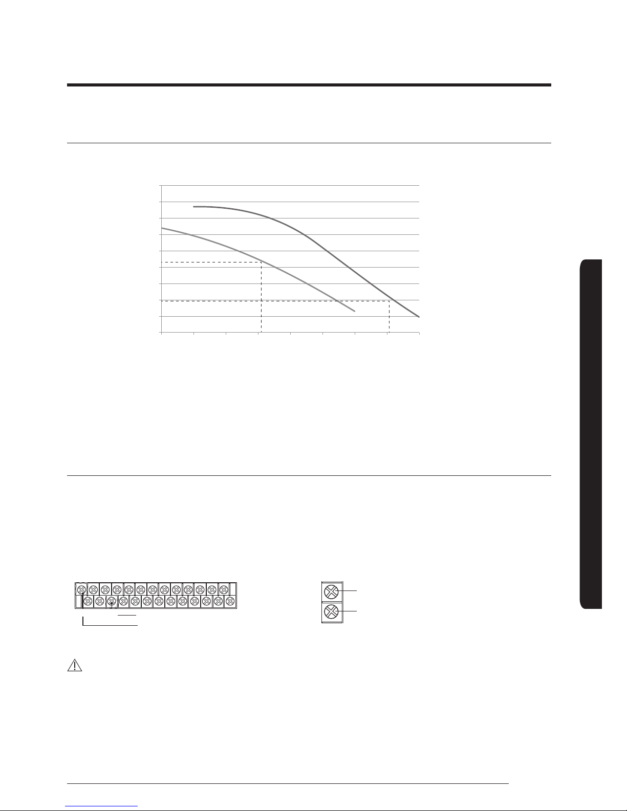
ESP(External Static Pressure) Diagram
The illustration below shows the external static pressure of the unit depending on the water flow and the pump setting.
16 kW
Flow [l/min]
ESP [kPa]
9 kW
Water flow rate
9 kW : 26 LPM
Water flow rate
16 kW : 46 LPM
0
10
20
30
40
43
50
60
70
80
90
10
15 20 2526 30 35 40 4546 50
If the pressure loss of total system is over 43(9kW) or 20(16kW)kPa, additional water pump should be installed in series.
Otherwise, the flow rate might decreased, causing insufficient heating or cooling.
When ESP is not enough, additional pump should be installed. In this case, install the PWM control external type pump (Heating
type) additionally.
Connection guide of additional pump
Case 1) INV. pump
Connect the PWM control external type pump to PWM terminal block and power cable to the external contact terminal.
The maximum number of additional pump installation is one inverter pumps (Input power 100W).
1 Power supply (INV. Pump) 2 PWM control (for INV. Pump only)
Live additional pump
Neutral additional pump
B6
B1
Reference (GND)
PWM signal (SIG)
CAUTION
• If there is wrong wiring between PWM and reference, INV. Water Pump may not work or wrong operation.
20
Pipe work
INSTALLATION
English
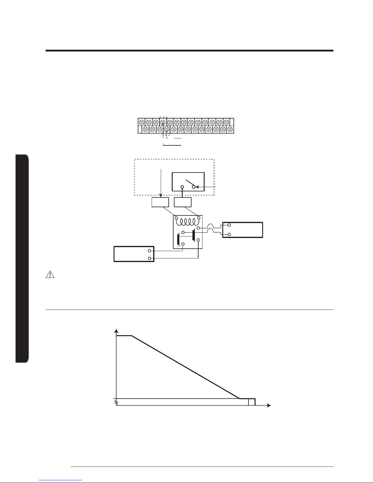
Case 2) AC pump
The maximum number of additional pump installation is one AC pumps (Input power 100W).
1 Power supply (AC Pump)
Live additional pump
Neutral additional pump
B7
B8
L
N
M/C
PCB
Terminal block
Neutral additional pump
Live additional pump
B7 B8
Pump
Power
CAUTION
• Terminal of this product is for additional water pump and the maximum allowable current is 0.5 A.
PWM characteristic curve
PWM input signal(%)
Max.
Speed
The additional pump should be the same type of product as the above graph.
Recommendation
• 9kW (AE090∗∗∗) : GRUNDFOS UPM3 25-75 (Heating Type)
• 16kW (AE160∗∗∗) : WILO STRATOS PARA 25/1-9 (Heating Type)

21
INSTALLATION
English
Setting the pre-pressure of the expansion vessel
When it is required to change the default pre-pressure of the expansion vessel(1 bar), keep in mind the following guidelines:
• Use only dry nitrogen to set the expansion vessel pre-pressure.
• Inappropriate setting of the expansion vessel pre-pressure will lead to malfunction of the system. Therefore, the pre-pressure
should only be adjusted by a licensed installer.
[Lit]
50 100 150 200 250 300 350 400
14.00
12.00
10.00
8.00
6.00
4.00
2.00
0.00
Water volume (Litre) in total system including pipes
Operation range
Norminal
Expansion Vessel capacity (Liter)
CAUTION
• Water volume of total system for reliable performance is minimum 50 liters.
Installation height
difference
a)
Water volume
< 220 Litres > 220 Litres
< 7m No pre-pressure adjustment required.
Actions required:
• Pre-pressure must be decreased, calculate
according to “Calculating the pre-pressure
of the expansion vessel”.
• Check if the water volume is lower than
maximum allowed water volume
> 7m
Actions required:
• Pre-pressure must be increased, calculate
the appropriate value following by
“Calculating the pre-pressure of the
expansion vessel”.
• Check if the water volume is lower than
maximum allowed water volume
Expansion vessel of the unit too small for the
installation.
a) Installation height difference: height difference(m) between the highest point of the water circuit and the indoor unit. If the
indoor unit is located at the highest point of the installation, the installation height is considered 0m.
Calculating the pre-pressure of the expansion vessel
The pre-pressure(Pg) to be set depends on the maximum installation height difference(H) and is calculated as below:
Pg=(H/10+0.3) bar
22
Pipe work
INSTALLATION
English
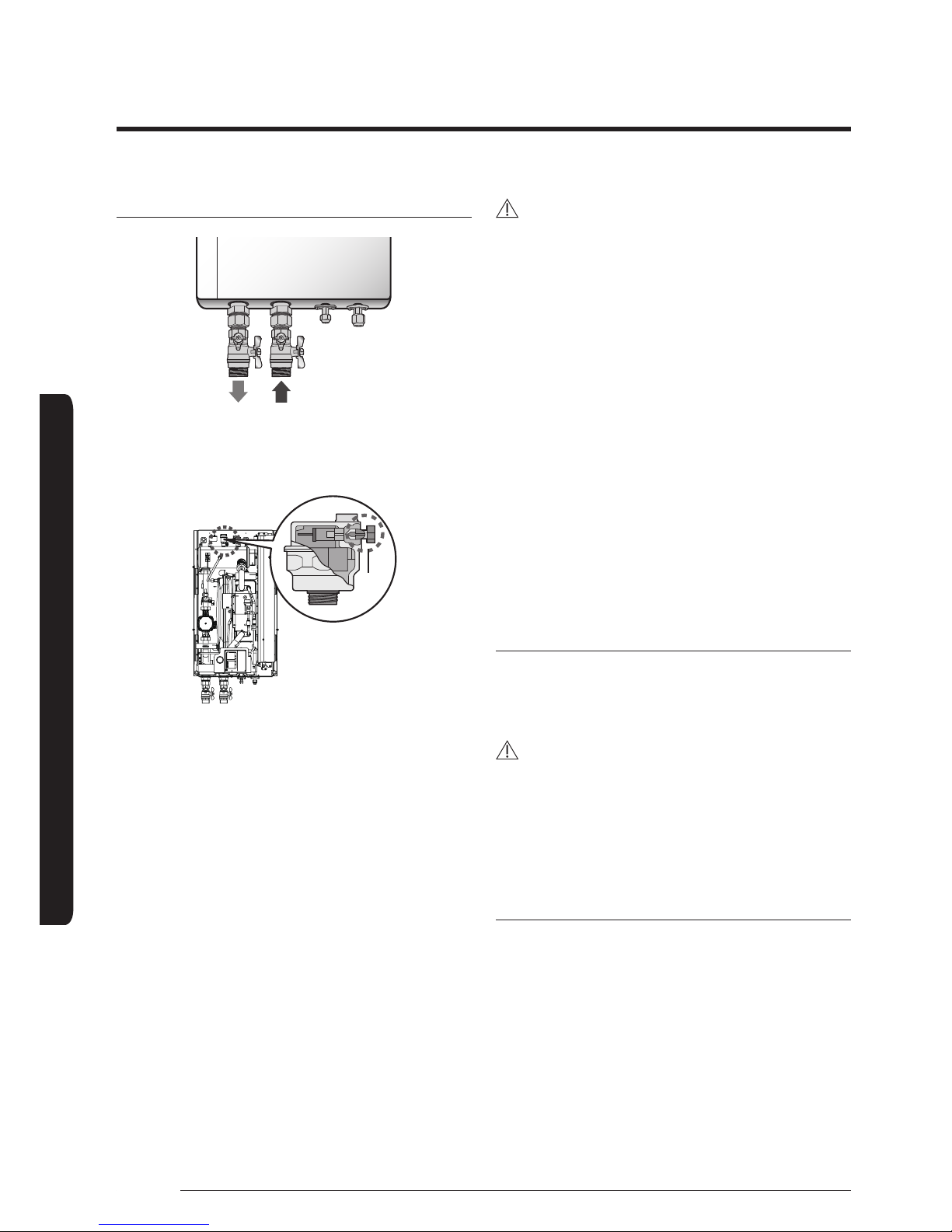
Charging water
WATER
OUTLET
WATER
INLET
Liquid
pipe
Gas
pipe
Air-vent valve
Cap
After installation is completed the following procedures shall
be used to charge water into the hydro unit.
• Connect water lines to water connections of hydro unit.
• The air-vent valve shall be opened at least 2 turns and
drain valves shall be closed.
• Open the service valve in the water supply connection.
• Water pressure of supply line shall be over 2.0 bar for good
charging work.
• Stop water supply when the pressure gauge of hydro unit
indicates 2.0 bar.
CAUTION
• Service space should be secured.
• Water pipe and connections must be cleaned using water.
• If internal water pump capacity is not enough, install
external water pump.
• Do not connect electric wire while water charging.
• When initial installation or re-installation required, open
the cap to prevent air trap in the unit while charging water.
• The back-up heater vessel shall be full of water before
heater is turned on. Confirm if the vessel is empty by
opening the pressure relief valve of hydro unit. (OK if water
is flowing out)
• It is recommended to install the make-up water
assembly to feed small quantities of water to the system
automatically, replacing the minor water losses and
maintaining the system pressure. This assembly usually
consists of a pressure-reducing valve, water filter, check-
valve and shut-off valves. In this case, Check-valve must be
installed to prevent from contaminating city water.
Pressure relief valve
A pressure relief valve is integrated on heater vessel of hydro
unit and shall work in abnormal condition for protecting the
hydro unit.
CAUTION
• The pressure relief valve will operate releasing the
pressure by flowing out some water through the drain
hose.
• Make certain that the discharged water out of drain pan
can not contact any electrical parts.
Piping insulation
The complete water circuit, including all piping must be
insulated to prevent condensation forming on the surface of
the pipe and heat loss to external environment.
23
INSTALLATION
English
Wiring work
CAUTION
• Field-supplied electrical components such as power switch, circuit breakers, wires, terminal blocks, etc must be properly
chosen with compliance with national legislation or regulation.
• Switch off the power supply before making any connections.
• All field wiring and components must be installed by a licensed electrician.
• Use a dedicated power supply.
• All power connections must be protected from dew condensation by thermal insulation.
• The system shall be earthed. Do not earth the unit to a utility pipe, surge absorber or telephone earth. Incomplete earth may
cause electrical problems.
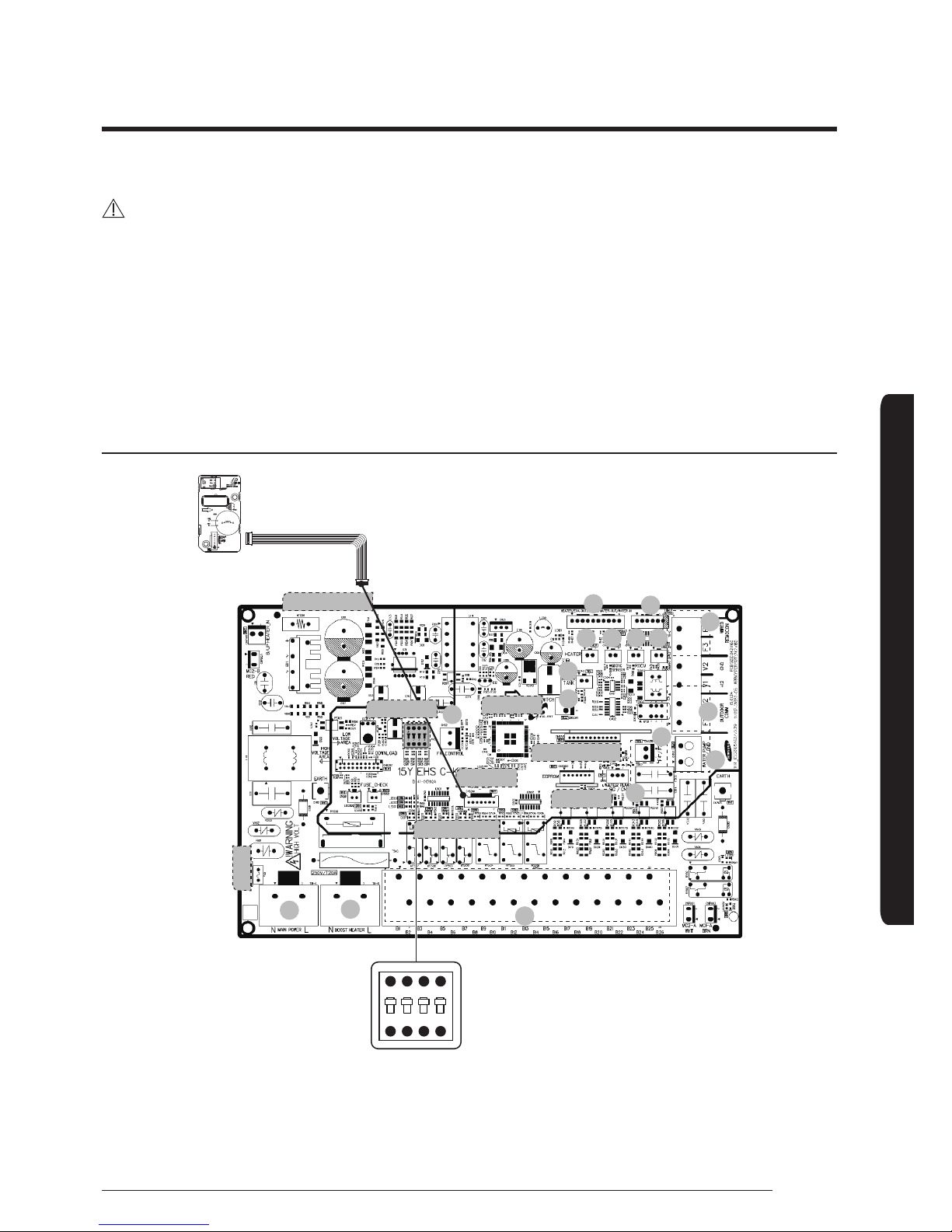
Layout of PCB
1ON2 3 4
SMPS circuit
Micom
LED
EEPROM
2-WIRE COMM
Load control
Fuse
01
02
03
04
05 06
07
08
09
10
11
17
16
15
14
13
12
DIP switch
24
Wiring work
INSTALLATION
English
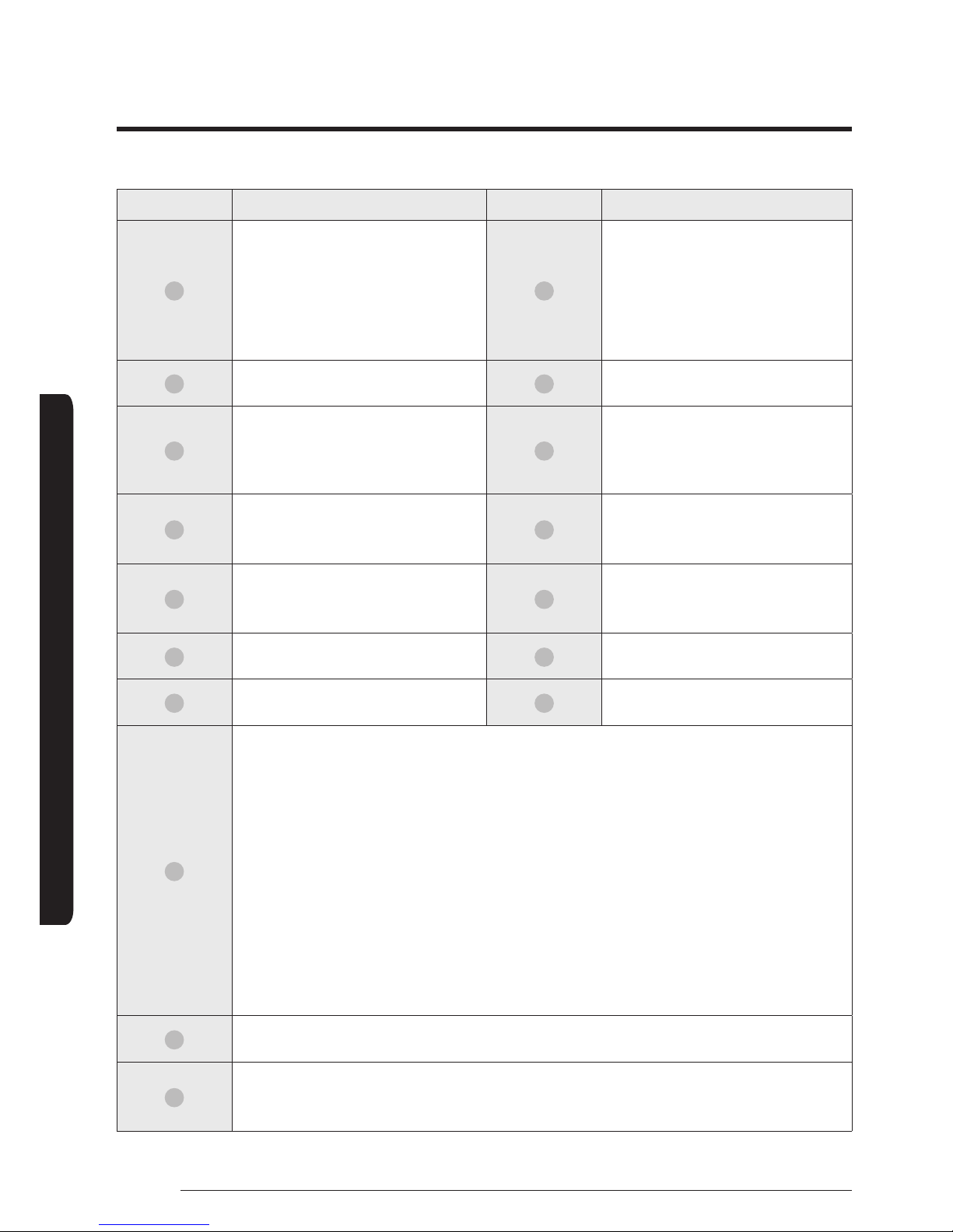
No. Note No. Note
01
FR Control
CNS2(Green)
08
CNS043(White)
1-2:Heater Out
3-4:Eva Out
5-6:Eva in
7-8:Water Out
9-10:Water In
02
Flow Switch
CNS041(Blue)
09
EEV
CNS063(Blue)
03
Water Tank
CNS042(Yellow)
10
TB-C (Black)
F3-F4:COMM2 (Wired remote controller)
INPUT/OUTPUT, DC, 210 mA (per each
controller)
04
Heater Out(Mono)
CNS047(Black)
11
TB-C (Black)
F1-F2:COMM1 (IN-OUT COMM)
INPUT/OUTPUT, DC, 10 mA
05
Mixing Sensor
CNS045(Blue)
12
CNS1(White)
1:Signal
3:Gnd
06
Room Sensor
CNS044(White)
13
Boost Heater TB-A1 (Black)
L-N, OUTPUT AC
07
Smart Grid
CNS046(Red)
14
Main Power TB-A(Black)
L-N, INPUT, AC
15
TB-B(Black)
B1:Neutral_INV PUMP,
OUTPUT, AC
B2:Mixing Valve_CW,
OUTPUT, AC
B3:Mixing Valve_CCW,
OUTPUT, AC
B4:Boiler, OUTPUT, AC
B5:Neutral, OUTPUT,
AC
B6:Lived_INV
PUMP, OUTPUT,
AC
B7:Neutral,
OUTPUT, AC
B8:Lived, OUTPUT,
AC
B9:2WAY1_NO,
OUTPUT, AC
B10:2WAY1_NC,
OUTPUT, AC
B11:Neutral,
OUTPUT, AC
B12:Lived,
OUTPUT, AC
B13:2WAY2_NO,
OUTPUT, AC
B14:2WAY2_NC,
OUTPUT, AC
B15:Neutral,
OUTPUT, AC
B16:Lived,
OUTPUT, AC
B17:3WAY_NO,
OUTPUT, AC
B18:3WAY_NC,
OUTPUT, AC
B19:Neutral,
OUTPUT, AC
B20:Lived, OUTPUT,
AC
B21:THERM01_C,
INPUT, AC
B22:THERM01_H,
INPUT, AC
B23:THERM02_C,
INPUT, AC
B24:THERM02_H,
INPUT, AC
B25:Solar/
Thermostat_N,
INPUT, AC
B26:Solar/
Thermostat_L,
INPUT, AC
16
CNS304(RED)
F3-F4:COMM2 (Wired Remote controller)
17
CNS3(Black)
1:Signal
2:Gnd
25
INSTALLATION
English
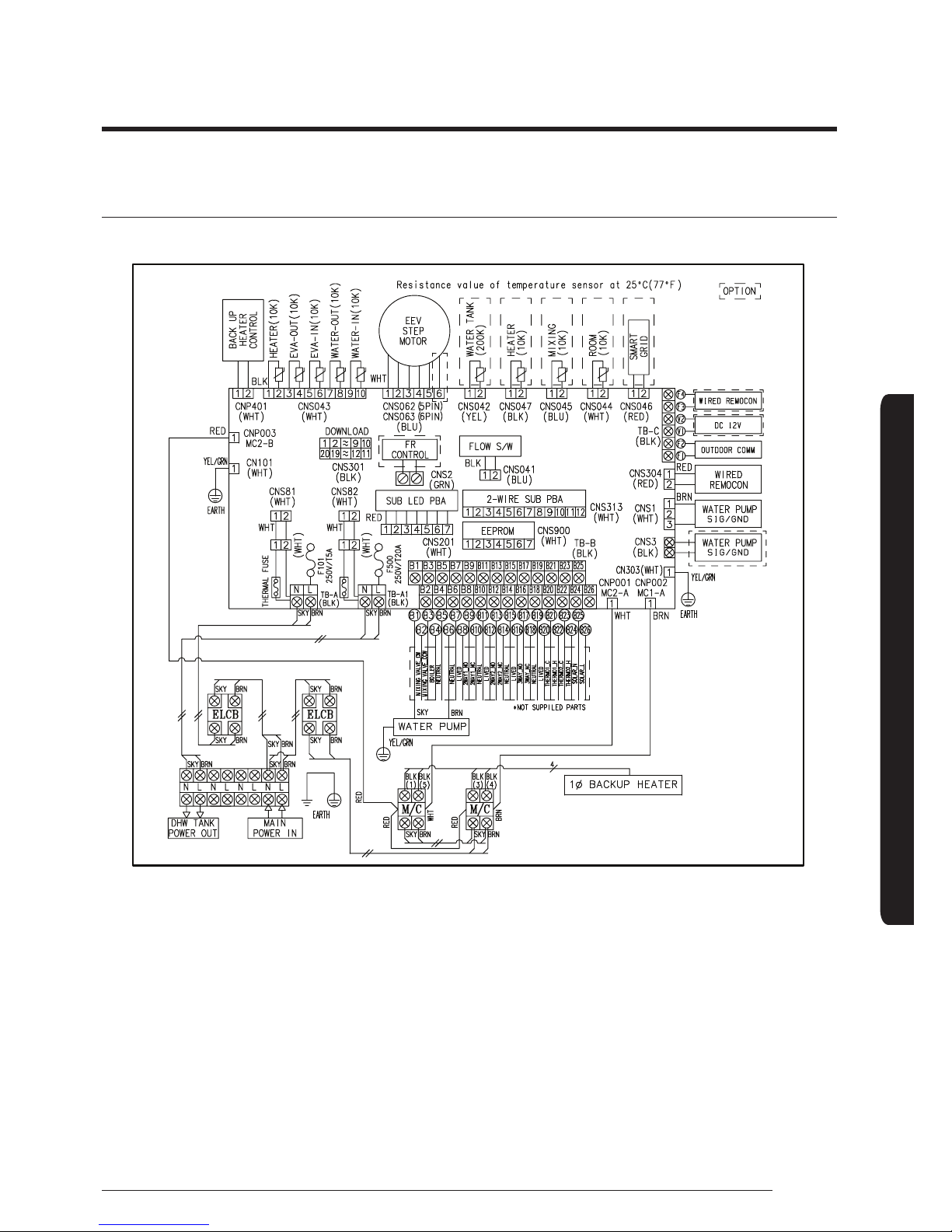
Wiring diagram (AE090MNYDEH/AE160MNYDEH) 1-Phase
26
Wiring work
INSTALLATION
English
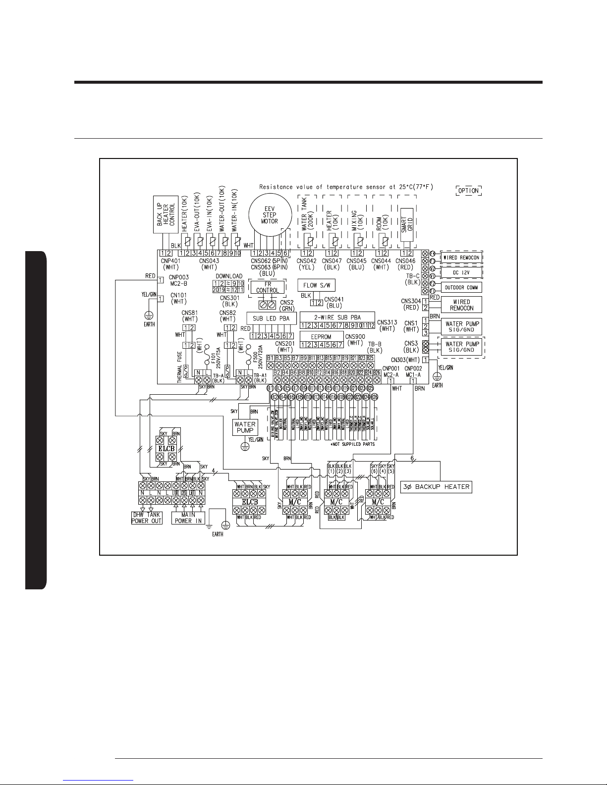
Wiring diagram ( AE090MNYDGH/AE160MNYDGH) 3-Phase
27
INSTALLATION
English
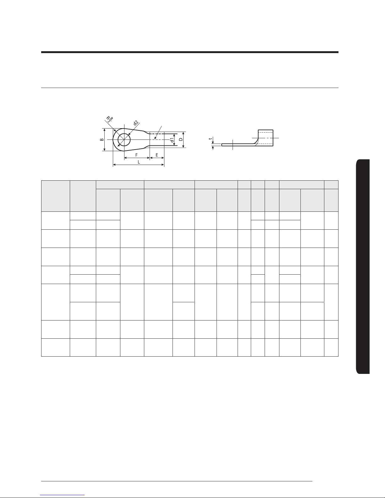
Selecting solderless ring terminal
• Select a solderless ring terminal of a connecting power cable based on a nominal dimensions for cable.
• Cover a solderless ring terminal and a connector part of the power cable and then connect it.
Nominal
dimensions
for cable
(mm
2
)
Nominal
dimensions
for screw
(mm)
B D d1 E F L d2 t
Standard
dimension
(mm)
Allowance
(mm)
Standard
dimension
(mm)
Allowance
(mm)
Standard
dimension
(mm)
Allowance
(mm)
Min. Min. Max.
Standard
dimension
(mm)
Allowance
(mm)
Min.
4/6
4 9.5
±0.2 5.6
+0.3
-0.2
3.4 ±0.2 6
5 20 4.3 +0.2
0
0.9
8 15 9 28.5 8.4
10 8 15 ±0.2 7.1
+0.3
-0.2
4.5 ±0.2 7.9 9 30 8.4
+0.4
0
1.15
16 8 16 ±0.2 9
+0.3
-0.2
5.8 ±0.2 9.5 13 33 8.4
+0.4
0
1.45
25
8 12
±0.3 11.5
+0.5
-0.2
7.7 ±0.2 11
15
34
8.4 +0.4
0
1.7
8 16.5 13 8.4
35
8 16
±0.3 13.3
+0.5
-0.2
9.4 ±0.2 12.5
13 38 8.4
+0.4
0
1.8
8 22
+0.5
-0.2
13 43 8.4
+0.4
0
50 8 22 ±0.3 13.5
+0.5
-0.2
11.4 ±0.3 17. 5 14 50 8.4
+0.4
0
1.8
70 8 24 ±0.4 1 7.5
+0.5
-0.4
13.3 ±0.4 18.5 20 51 8.4
+0.4
0
2
28
Wiring work
INSTALLATION
English
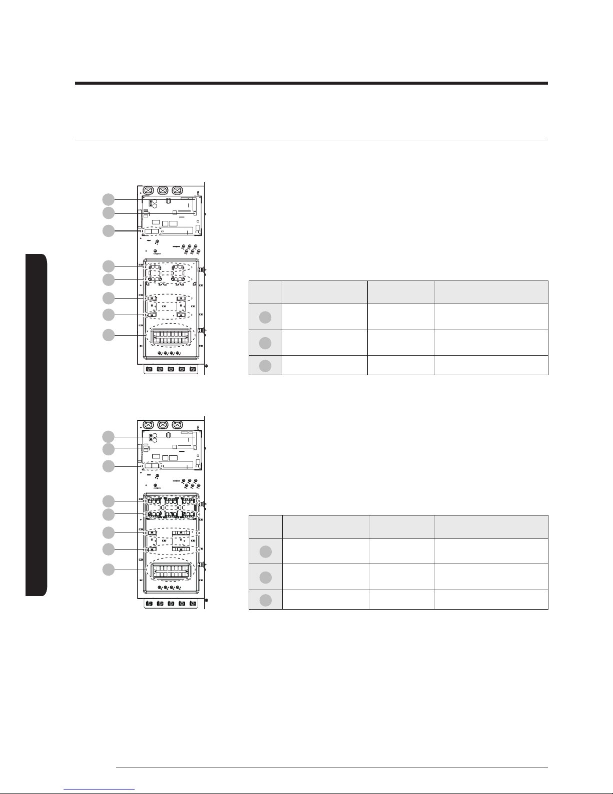
Torque requirements
1 Phase
01
02
03
03
03
03
03
03
No. Terminal name Specification Tightening Torque (N · m)
01
PWM control
(INV. Pump)
M3 0.5 ~ 0.75
02
Communication &
External contact
M3.5 0.8 ~ 1.2
03
Power M4 1.2 ~ 1.8
3 Phase
01
02
03
03
03
03
03
03
No. Terminal name Specification Tightening Torque (N · m)
01
PWM control
(INV. Pump)
M3 0.5 ~ 0.75
02
Communication &
External contact
M3.5 0.8 ~ 1.2
03
Power M4 1.2 ~ 1.8
29
INSTALLATION
English
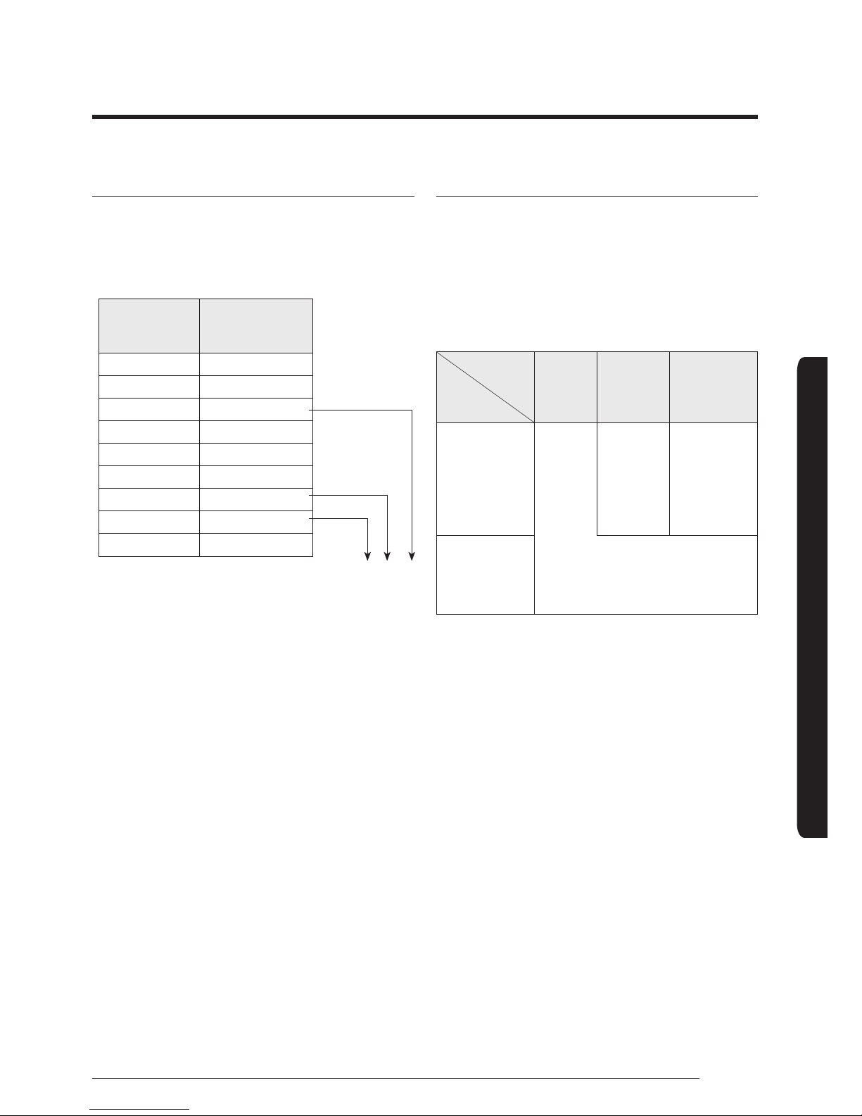
Types of allowable current
Conductors of supply cord shall have a nominal cross-sectional
area not less than that shown in the table below.
Minimum cross-sectional area of conductors
Rated current
of appliance (A)
Nominal
cross-sectional
area (mm2)
≤0.2 Tinsel cord
a)
≤0.2 and ≤3 0.5
a)
>3 and ≤6 0.75
>6 and ≤10 1.0(0.75)
b)
>10 and ≤16 1.5(1.0)
b)
>16 and ≤25 2.5
>25 and ≤32 4
>32 and ≤40 6
>40 and ≤63 10
a) These cords may only be used if their length does not
exceed 2m between the point where the cord or cord
guard enters the appliance and the entry to the plug.
b) Cords having the cross-sectional areas indicated in the
parentheses may be used for portable appliances if their
length does not exceed 2m.
Grounding work
• Grounding must be done by a qualified installer for your
safety.
Grounding the power cable
• The standard of grounding may vary according to the rated
voltage and installation place of a heating pump.
• Ground the power cable according to the following.
Installation
place
Power
condition
High
humidity
Average
humidity
Low humidity
Electrical
potential of
lower than 150V
Perform
the
grounding
work 3.
Note 1)
Perform the
grounding
work 3 if
possible for
your safety.
Note 1)
Electrical
potential of
higher than
150V
Must perform the grounding work 3.
Note 1)
(In case of installing circuit breaker)
∗ Note 1) Grounding work 3
• Grounding must be done by your installation specialist.
• Check if the grounding resistance is lower than 100Ω.
When installing a circuit breaker that can cut the electric
circuit in case of a short circuit, the allowable grounding
resistance can be 30~500Ω.
Exterior connection
DHW Power IN/OUT
Main power
30
Wiring work
INSTALLATION
English
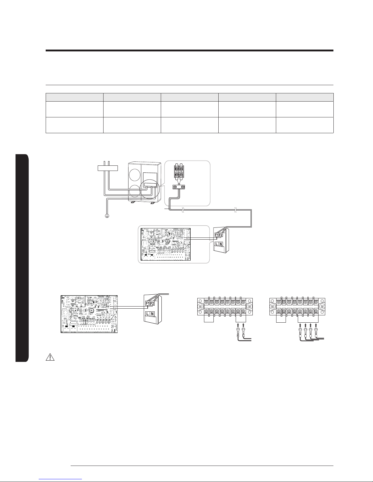
Connection of the power supply and communication cable
Description No. of wires Max. A Thickness Supply Scope
Main power 2+ground 32A
4.0mm
2
H05RN-F or
H07RN-F
Field supply
(230V~, Input)
Communication 2 6A
0.75mm
2
H05RN-F or
H07RN-F
7Vdc data
2 wires for communication cable
Earth
Communication cable
between indoor and
outdoor units
Communication
cable
Hydro unit
Circuit breaker
Communication cable connection Power wire connection
N
N L
N L
L N L N L
DHW TANK
POWER OUT
MAIN
POWER IN
1 phase
N
N
L
T N
L N L T N
R S
R S
T N
R S
DHW TANK
POWER OUT
MAIN POWER IN
3 phase
CAUTION
• If the supply cable is damaged, it must be replaced by a special cable or assembly available from the manufacturer or installer.
• Circuit Breaker (ELCB, ELB, MCCB etc.) for outdoor and indoor units shall be installed by installers because they are not sub-
parts in the units. But you don't need to install for hydro unit (Built-in ELCB).
– ELCB : Earth leakage circuit breaker
– ELB : Earth leakage breaker
– MCCB : Molded case circuit breaker
 Loading...