

Samsung AE071MNMPEH, AE036MNLDEH, AE022MNLDEH, AE056MNLDEH, AE028MNLDEH Installation Manual
...
Air conditioner
Installation manual
AE
MNLDEH / AE
MNMPEH
• Thank you for purchasing this Samsung air conditioner.
• Before operating this unit, please read this manual carefully and retain it for future
reference.

2
English
Contents
Safety Information 3
Installation Procedure 5
Step 1 Checking and preparing accessories
Step 2 Choosing the installation location
Step 3 Optional: Insulating the body of the indoor unit
Step 4 Installing the indoor unit
Step 5 Purging inert gas from the indoor unit
Step 6 Cutting or flaring the pipes
Step 7 Connecting the assembly pipes to the refrigerant pipes
Step 8 Performing the gas leak test
Step 9 Insulating the refrigerant pipes
Step 10 Installing the drain hose and drain pipe
Step 11 Performing the drainage test
Step 12 Connecting the power and communication cables
Step 13 Optional: Extending the power cable
Step 14 Setting an indoor unit address and installation option
Step 15 External Static Pressure (ESP) setting for phase control motor
Step 16 Setting temperature control of discharge air
Step 17 Performing the final check
Step 18 Providing information for user
Appendix 38
Troubleshooting
3
English
Safety Information
WARNING
• Hazards or unsafe practices that may result in severe
personal injury or death.
CAUTION
• Hazards or unsafe practices that may result in minor
personal injury or property damage.
• Carefully follow the precautions listed below because
they are essential to guarantee the safety of the
equipment.
WARNING
• Always disconnect the air conditioner from the power
supply before servicing it or accessing its internal
components.
• Verify that installation and testing operations are
performed by qualified personnel.
• Verify that the air conditioner is not installed in an
easily accessible area.
General information
WARNING
• Carefully read the content of this manual before
installing the air conditioner and store the manual in
a safe place in order to be able to use it as reference
after installation.
• For maximum safety, installers should always
carefully read the following warnings.
• Store the operation and installation manual in a safe
location and remember to hand it over to the new
owner if the air conditioner is sold or transferred.
• This manual explains how to install an indoor unit
with a split system with two SAMSUNG units. The use
of other types of units with different control systems
may damage the units and invalidate the warranty.
The manufacturer shall not be responsible for
damages arising from the use of non compliant units.
• The manufacturer shall not be responsible for damage
originating from unauthorized changes or the
improper connection of electric and requirements set
forth in the “Operating limits” table, included in the
manual, shall immediately invalidate the warranty.
• The air conditioner should be used only for the
applications for which it has been designed: the
indoor unit is not suitable to be installed in areas
used for laundry.
• Do not use the units if damaged. If problems occur,
switch the unit off and disconnect it from the power
supply.
• In order to prevent electric shocks, fires or injuries,
always stop the unit, disable the protection switch
and contact SAMSUNG’s technical support if the unit
produces smoke, if the power cable is hot or damaged
or if the unit is very noisy.
• Always remember to inspect the unit, electric
connections, refrigerant tubes and protections
regularly. These operations should be performed by
qualified personnel only.
• The unit contains moving parts, which should always
be kept out of the reach of children.
• Do not attempt to repair, move, alter or reinstall the
unit. If performed by unauthorized personnel, these
operations may cause electric shocks or fires.
• Do not place containers with liquids or other objects
on the unit.
• All the materials used for the manufacture and
packaging of the air conditioner are recyclable.
• The packing material and exhaust batteries of the
remote controller(optional) must be disposed of in
accordance with current laws.
• The air conditioner contains a refrigerant that has
to be disposed of as special waste. At the end of its
life cycle, the air conditioner must be disposed of in
authorised centres or returned to the retailer so that
it can be disposed of correctly and safely.
Safety Information
4
Contents
English
Safety Information
Installing the unit
WARNING
IMPORTANT: When installing the unit, always remember
to connect first the refrigerant tubes, then the electrical
lines.
• Always disassemble the electric lines before the
refrigerant tubes.
• Upon receipt, inspect the product to verify that
it has not been damaged during transport. If the
product appears damaged, DO NOT INSTALL it and
immediately report the damage to the carrier or
retailer (if the installer or the authorized technician
has collected the material from the retailer.)
• After completing the installation, always carry out a
functional test and provide the instructions on how to
operate the air conditioner to the user.
• Do not use the air conditioner in environments with
hazardous substances or close to equipment that
release free flames to avoid the occurrence of fires,
explosions or injuries.
• Our units should be installed in compliance with the
spaces shown in the installation manual, to ensure
accessibility from both sides and allow repairs
or maintenance operations to be carried out. The
unit’s components should be accessible and easy to
disassemble without endangering people and objects.
For this reason, when provisions of the installation
manual are not complied with, the cost required to
access and repair the units (in SAFETY CONDITIONS,
as set out in prevailing regulations) with harnesses,
ladders, scaffolding or any other elevation system
will NOT be considered part of the warranty and will
be charged to the end customer.
Power supply line, fuse or circuit
breaker
WARNING
• Always make sure that the power supply is compliant
with current safety standards. Always install the air
conditioner in compliance with current local safety
standards.
• Always verify that a suitable grounding connection is
available.
• Verify that the voltage and frequency of the power
supply comply with the specifications and that the
installed power is sufficient to ensure the operation
of any other domestic appliance connected to the
same electric lines.
• Always verify that the cut-off and protection switches
are suitably dimensioned.
• Verify that the air conditioner is connected to the
power supply in accordance with the instructions
provided in the wiring diagram included in the
manual.
• Always verify that electric connections (cable entry,
section of leads, protections…) are compliant with
the electric specifications and with the instructions
provided in the wiring scheme. Always verify that all
connections comply with the standards applicable to
the installation of air conditioners.
• Devices disconnected from the power supply should
be completely disconnected in the condition of
overvoltage category.
• Be sure not to perform power cable modification,
extension wiring, and multiple wire connection.
– It may cause electric shock or fire due to poor
connection, poor insulation, or current limit override.
– When extension wiring is required due to power line
damage, refer to "Step 13 Optional: Extending the
power cable" in the installation manual.
5
Installation Procedure
English
CAUTION
Make sure that you earth the cables.
• Do not connect the earth wire to the gas pipe, water
pipe, lighting rod or telephone wire. If earthing is not
complete, electric shock or fire may occur.
Install the circuit breaker.
• If the circuit breaker is not installed, electric shock or
fire may occur.
Make sure that the condensed water dripping from the
drain hose runs out properly and safely.
Install the power cable and communication cable of
the indoor and outdoor unit at least 1m away from the
electric appliance.
Install the indoor unit away from lighting apparatus
using the ballast.
• If you use the wireless remote control, reception error
may occur due to the ballast of the lighting apparatus.
Do not install the air conditioner in following places.
• Place where there is mineral oil or arsenic acid. Resin
parts flame and the accessories may drop or water
may leak. The capacity of the heat exchanger may
reduce or the air conditioner may be out of order.
• The place where corrosive gas such as sulphuric acid
gas generates from the vent pipe or air outlet.
• The copper pipe or connection pipe may corrode and
refrigerant may leak.
• The place where there is a machine that generates
electromagnetic waves. The air conditioner may not
operate normally due to control system.
• The place where there is a danger of existing
combustible gas, carbon fibre or flammable dust.
• The place where thinner or gasoline is handled. Gas
may leak and it may cause fire.
Installation Procedure
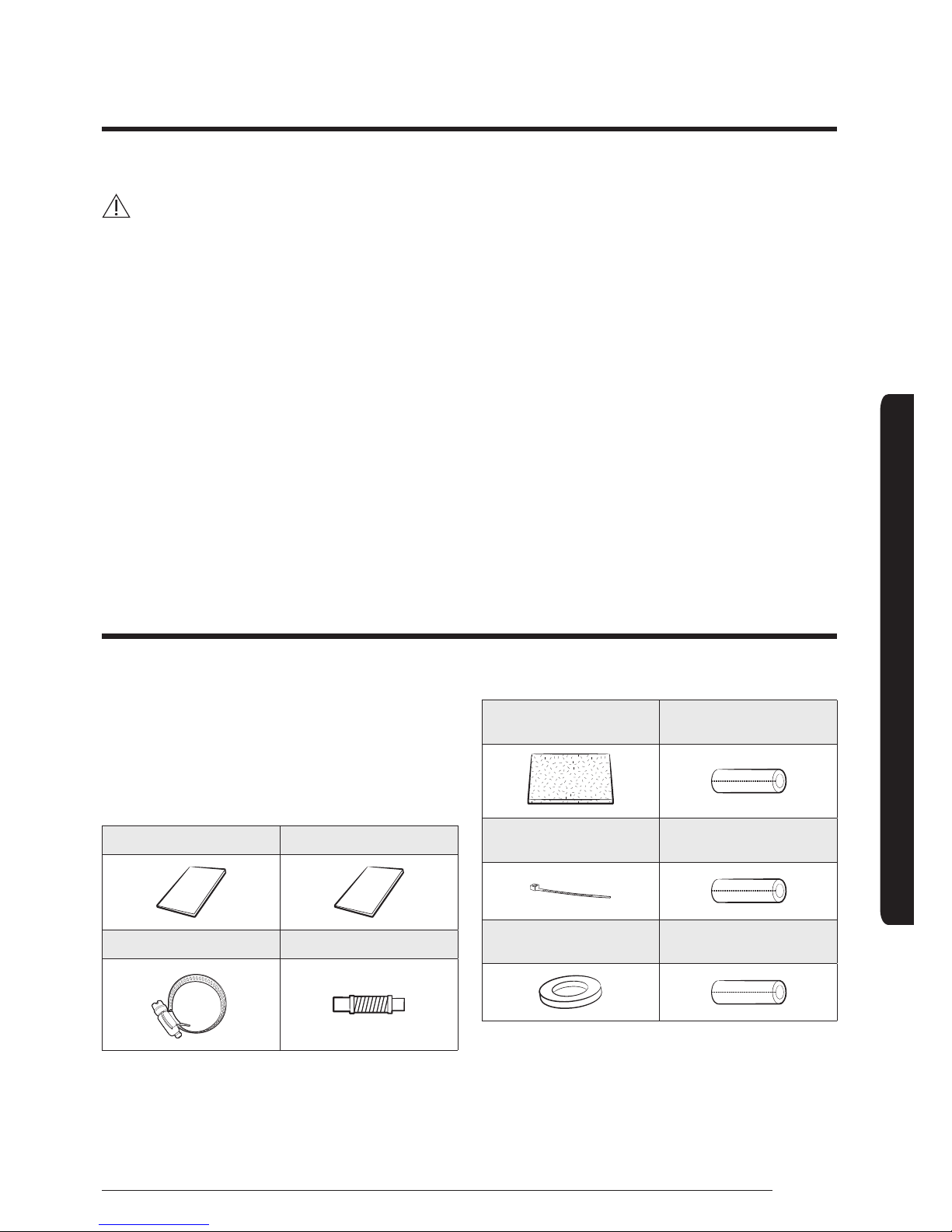
Step 1 Checking and preparing
accessories
The following accessories are supplied with the indoor
unit. The type and quantity may differ, depending on the
specifications.
User manual (1) Installation manual (1)
Clamp hose
(1)
Flexible hose (1)
Insulation drain (1)
Thermal insulation
sponge A (1)
Cable-tie (8)
Thermal insulation
sponge B (1)
Rubber
(8)
Thermal insulation
sponge C (1)
6
Installation Procedure
Installation Procedure
English
Step 2 Choosing the installation
location
General requirements for installation location
Do not install the air conditioner in a location where it
will come into contact with the following elements:
• Combustible gases
• Saline air
• Machine oil
• Sulphide gas
• Special environmental conditions
Avoid installing the air conditioner in a location with the
following conditions:
• In areas where it is exposed to direct sunlight. Close
to heat sources.
• In damp areas or locations where it could come into
contact with water. (for example rooms used for
laundry)
• In areas where curtains and furniture could affect the
supply and discharge of air.
• Without leaving the required minimum space around
the unit. (as shown in the drawing)
• In scarcely ventilated areas.
• On surfaces that are unable to support the weight
of the unit without deforming, breaking or causing
vibrations during the use of the air conditioner.
• In a position that does not enable the condensate
drainage pipe to be correctly installed. (at the end
of the installation. It is always essential to check the
efficiency of the drainage system)
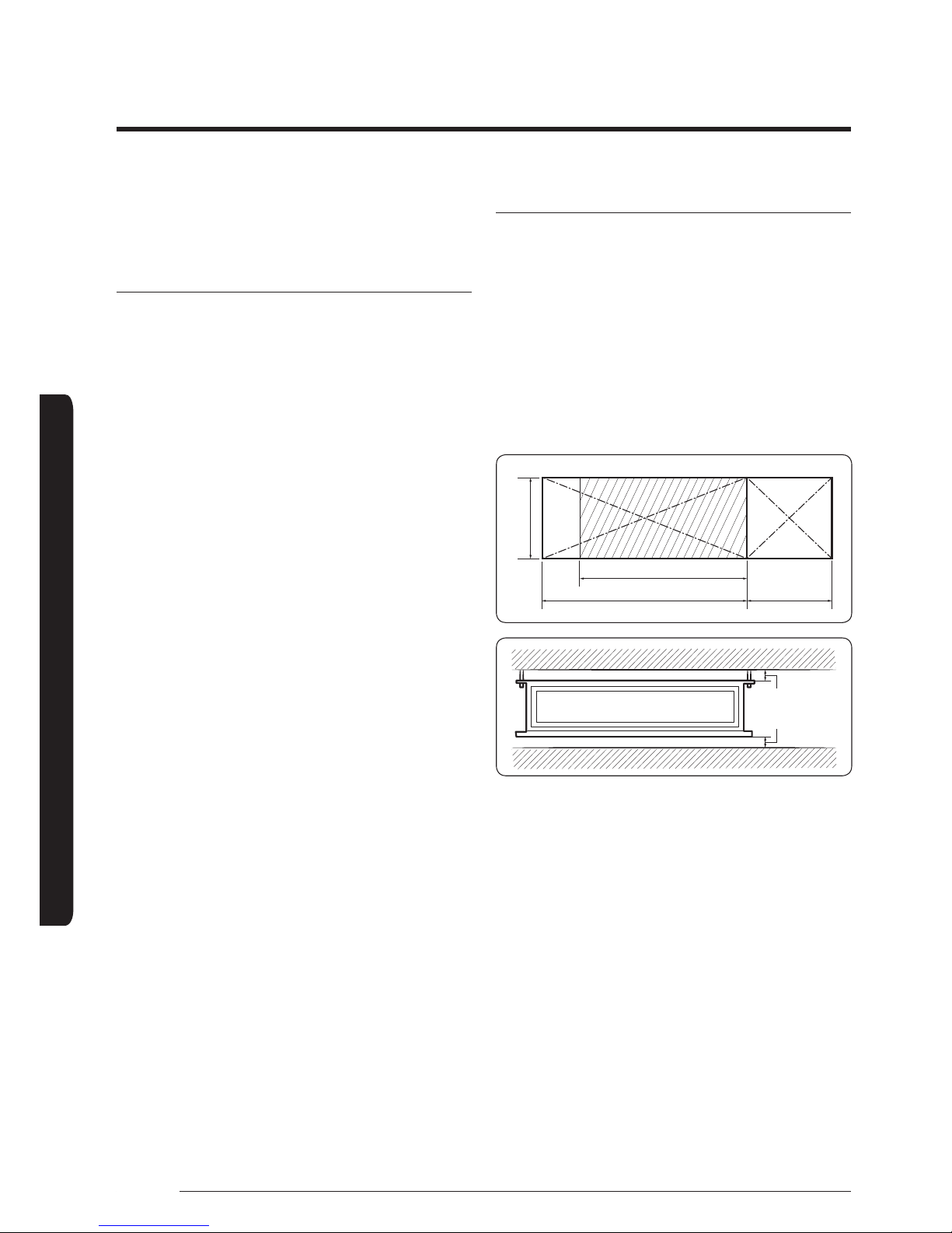
Space requirements for installation
Construction Standard for Inspection Hole
1 In case, the ceiling is tex tile, Inspection hole dose not
need.
2 In case, the ceiling is plaster board, Inspection hole
depends on Inside height of the ceiing.
a Height is more than 0.5m : Only "B" [Inspection
for PBA] is applied.
b Height is less than 0.5m : Both "A"&"B" are
applied.
c "A"&"B" are inspection holes .
Unit Depth(D)
"A"=W+100mm "B"=500mm
Unit Width(W)
20mm or more
20mm or more
• You must have 20 mm or more space between the
ceiling and the bottom of indoor unit. Otherwise, the
noise from the vibration of indoor unit may bother
the user. When the ceiling is under construction, the
hole for check-up must be made to take service, clean
and repair the unit.
• It is possible to install the unit at an height of
between 2.2~2.5 m from the ground, if the unit has a
duct with a well defined lenght (300 mm or more), to
avoid fan motor blower contact.
• If you install the cassette or duct type indoor unit on
the ceiling with humidity over 80%, you must apply
extra 10 mm of polyethylene foam or other insulation
with similar material on the body of the indoor unit.
7
Installation Procedure
English
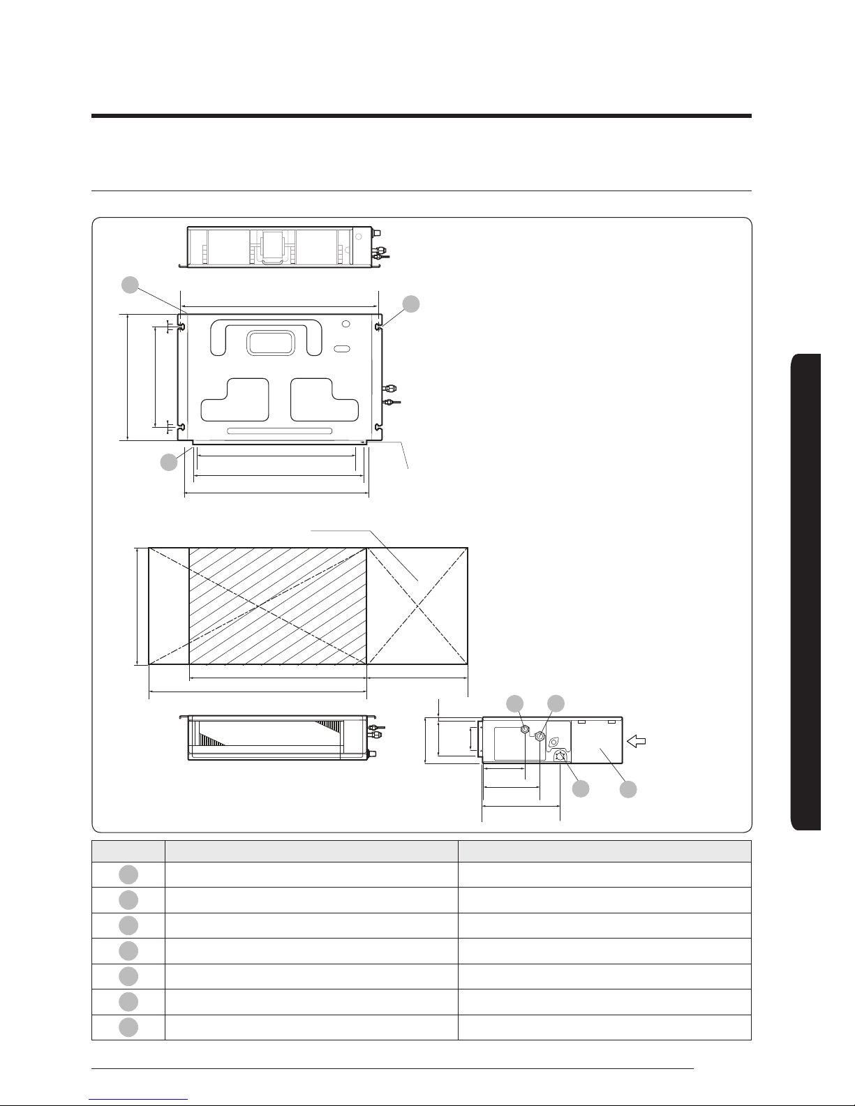
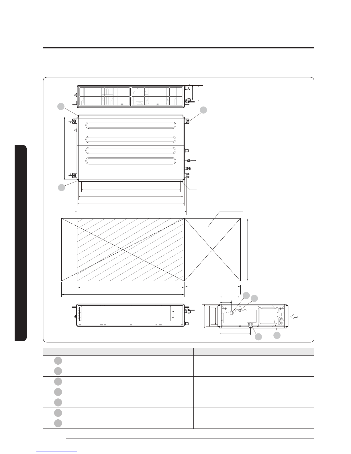
Indoor unit dimensions
AE022MNLDEH, AE028MNLDEH, AE036MNLDEH (Unit: mm)
600
700
800
500
Inspection hole
738.4 (Suspension position)
477 (Suspension position)
18-Ø3.2 hole
(Air around)
660 (Air outlet duct ange)
2828
600
600(6x100)
700
5
05
06
07
Suction side
333
199
Discharge side
182
246
151.6
18
100
02
01
03
04
No. Name Description
01
Liquid pipe connection ø6.35(1/4")
02
Gas pipe connection ø9.52(3/8")
03
Drain pipe connection OD25 ID20(without drain pump)
04
Power supply connection
05
Air discharge flange
06
Air filter
07
Hook M8~M10
8
Installation Procedure
Installation Procedure
English
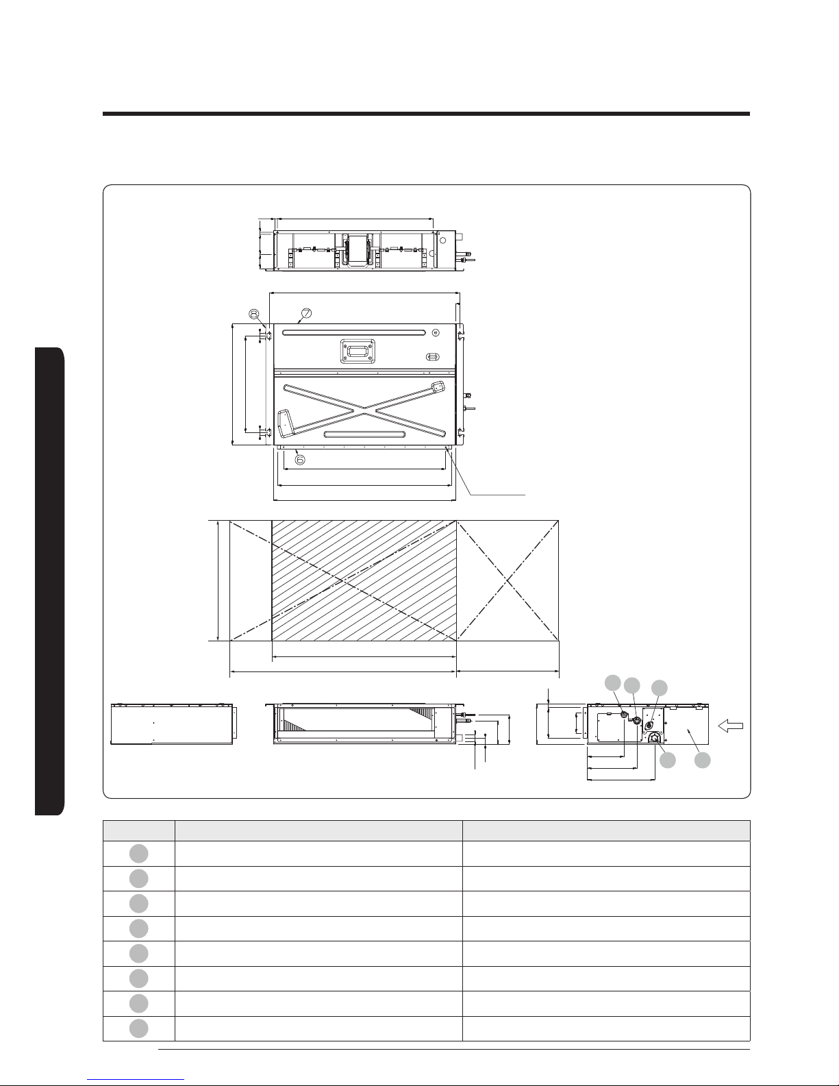
AE056MNLDEH (Unit: mm)
600
900
1000
500
01
02
04
03 05
11.9
3x256=768
71 100 10
938.4 Suspension position
600
477 Suspension position
8x100=800
860 Air outlet duct flange
900
22-ø3.2 Hole
28
28
All around
Discharge side Suction side
199
151.6
100
182
246
18
OD32
30.5
115.5
145.5
333
No. Name Description
01
Liquid pipe connection ø6.35(1/4")
02
Gas pipe connection ø12.70(1/2")
03
Drain pipe connection OD ø25 ID ø20
04
Drain pipe connection (Option drain pump) OD ø25 ID ø20
05
Power supply/Communication connection --
06
Power supply connection --
07
Air discharge grille flange --
08
Hook ø9.52 or M10
9
Installation Procedure
English
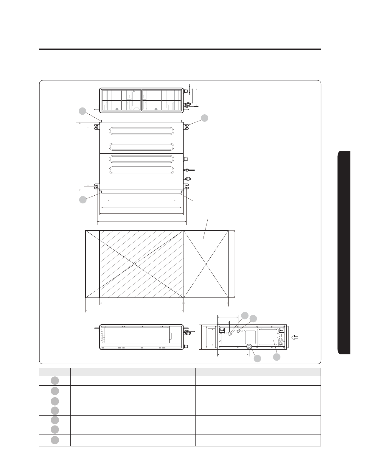
AE071MNMPEH (Unit: mm)
700
700(7x100)
817 (Air outlet duct ange)
850
22-ø3.2 hole
(Air around)
Inspection hole
Suction sideDischarge side
900 (Suspension position)
604 (Suspension position)
700
500850
950
185
158
28
220
180(2x90)
250
213
125
323
06
07
05
01
02
04
03
No. Name Description
01
Liquid pipe connection ø6.35(1/4")
02
Gas pipe connection
035: ø9.52(3/8"); 052/060: ø12.70(1/2")
071: ø15.88(5/8")
03
Drain pipe connection OD25 ID20(without drain pump)
04
Power supply connection
05
Air discharge flange
06
Air filter
07
Hook M8~M10
10
Installation Procedure
Installation Procedure
English
AE090MNMPEH (Unit: mm)
700
604
30-ø3.2 hole
(Air around)
1100(11x100)
1167 (Air outlet duct ange)
1200
1250 (Suspension position)
700
1200
500
1300
Suction sideDischarge side
220
180(2x90)
250
213
125
323
06
07
05
01
02
04
03
185
158
28
Inspection hole
No. Name Description
01
Liquid pipe connection ø9.52(3/8")
02
Gas pipe connection ø15.88(5/8")
03
Drain pipe connection OD25 ID20(without drain pump)
04
Power supply connection
05
Air discharge flange
06
Air filter
07
Hook M8~M10
11
Installation Procedure
English
Step 3 Optional: Insulating the body
of the indoor unit
A
D
B
C
Thickness: more than 10mm
Indoor
Unit
AE022MNLDEH
AE028MNLDEH
AE036MNLDEH
AE056MNLDEH
700 X 600 X 199
900 X 600 X 199
A 700 X 199 900 X 199
B 700 X 199 900 X 199
C 600 X 199 600 X 199
D 600 X 199 600 X 199
Front/
Back
Insulate the front and back side in proper size at
the same time when insulating the suction duct and
discharge duct.
(Unit: mm)
Indoor
Unit
AE071MNMPEH AE090MNMPEH
850 X 700 X 250 1200 X 700 X 250
A 850 X 250 1200 X 250
B 850 X 250 1200 X 250
C 700 X 250 700 X 250
D 700 X 250 700 X 250
Front/
Back
Insulate the front and back side in proper size at
the same time when insulating the suction duct and
discharge duct.
(Unit: mm)
NOTE
• Insulate the end of the pipe and some curved area by
using separate insulator.
• Insulate the discharge and suction part at the same
time when you insulate connection duct.
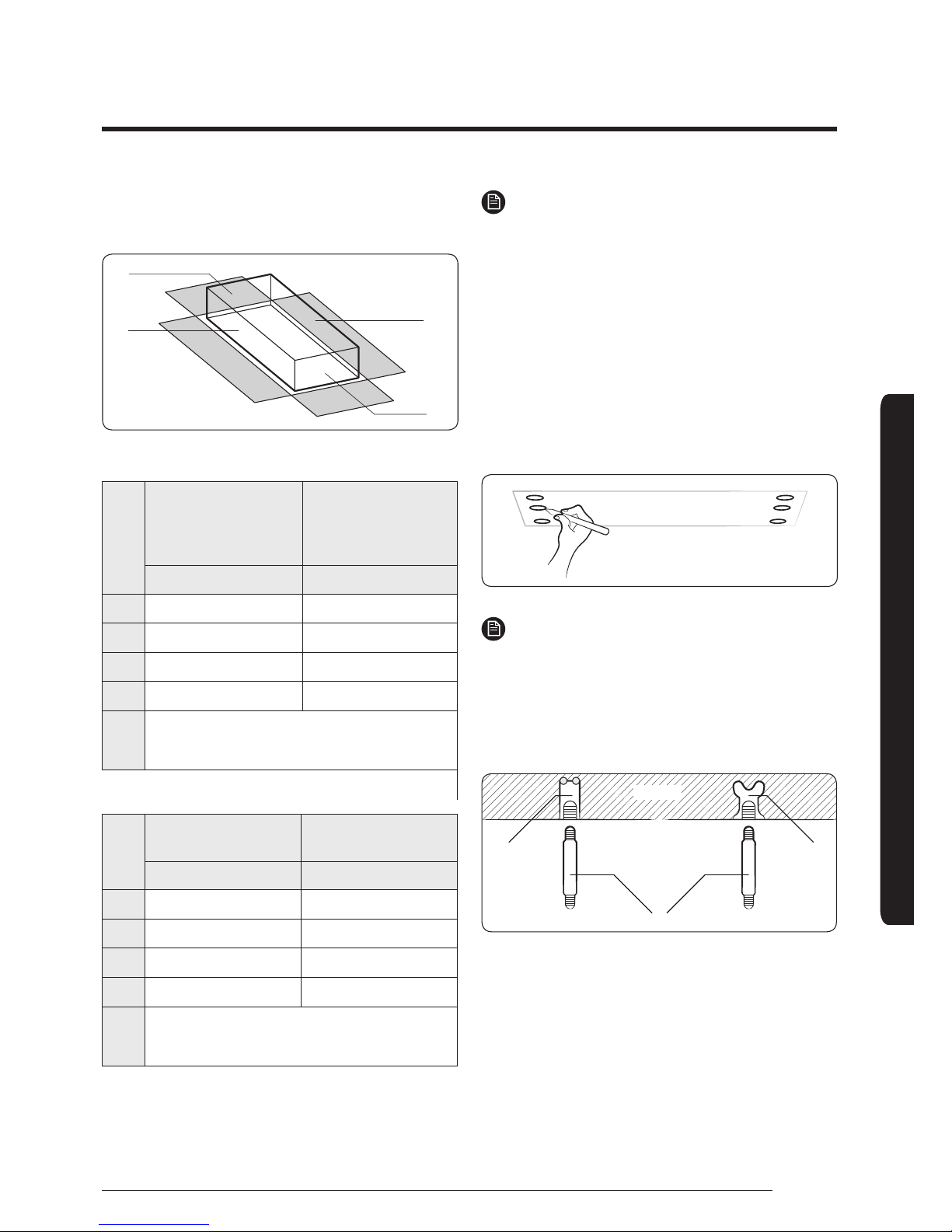
Step 4 Installing the indoor unit
When deciding on the location of the air conditioner
with the owner, the following restrictions must be taken
into account
1 Place the pattern sheet on the ceiling at the spot where
you want to install the indoor unit.
NOTE
• Since the diagram is made of paper, it may shrink or
stretch slightly due to temperature or humidity. For
this reason, before drilling the holes maintain the
correct dimensions between the markings.
2 Insert bolt anchors. Use existing ceiling supports or
construct a suitable support as shown in figure.
Concrete
Hole in anchor
Hole in plug
Suspension bolt (M8) - eld supply
Insert
3 Install the suspension bolts depending on the ceiling type.
12
Installation Procedure
Installation Procedure
English
Ceiling support
CAUTION
• Ensure that the ceiling is strong enough to support the
weight of the indoor unit. Before hanging the unit, test
the strength of each attached suspension bolt.
• If the length of suspension bolt is more than 1.5m,
it is required to prevent vibration.
• If this is not possible, create an opening on the false
ceiling in order to be able to use it to perform the
required operations on the indoor unit.
4 Screw eight nuts to the suspension bolts making space
for hanging the indoor unit.
NOTE
• You must install all the suspension rods.
5 Hang the indoor unit to the suspension bolts between
two nuts.
1
2
2
CAUTION
• Piping must be laid and connected inside the
ceiling when suspending the unit. If the ceiling is
already constructed, lay the piping into position for
connection to the unit before placing the unit inside
the ceiling.
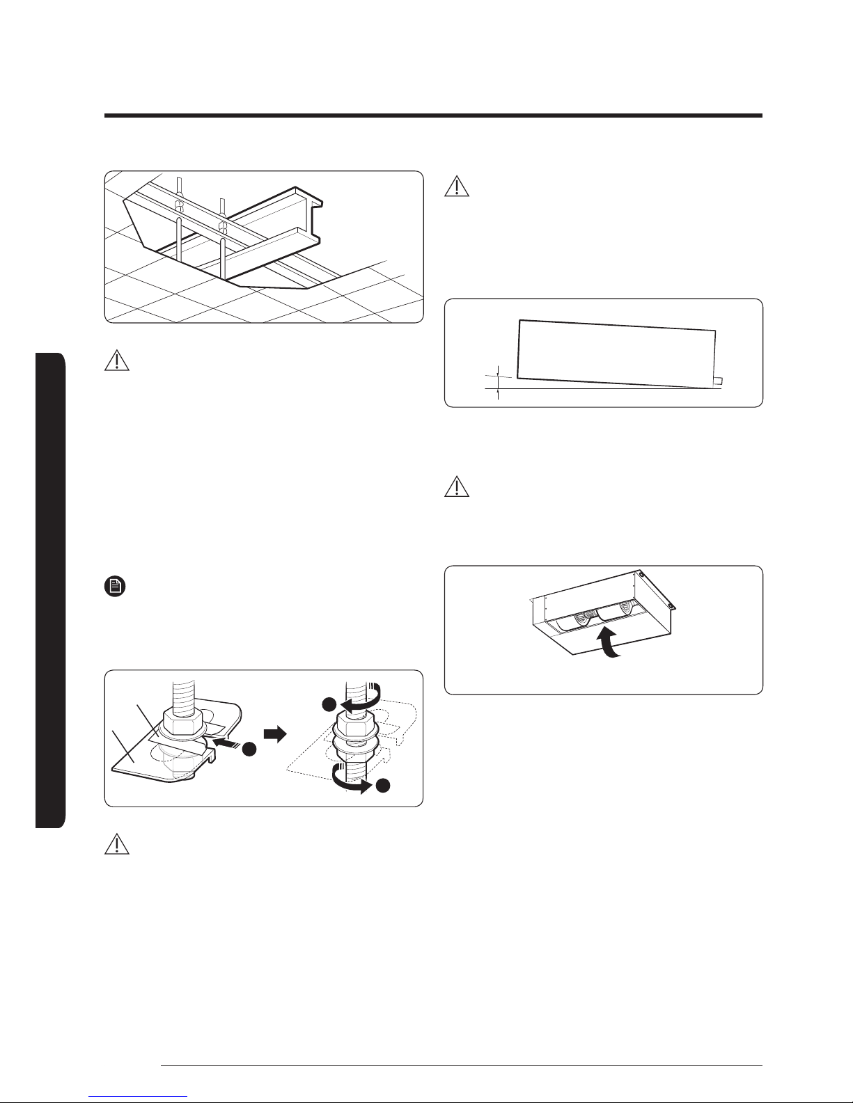
6 Screw the nuts to suspend the unit.
7 Adjust level of the unit by using measurement plate for
all 4 sides.
CAUTION
• For proper drainage of condensate, give a 3mm slant
to the left or right side of the unit which will be
connected with the drain hose, as shown in the figure.
Make a tilt when you wish to install the drain pump,
too.
When the drain hose is installed to the right.
Drain hose port
3mm
• When installing the indoor unit, make sure it is not
tilted toward front or b
ack side.
CAUTION
• Noise will increase 3~6 dB(A) when the air flow
enters from the bottom side (Only for Slim Duct Type
product).
Air Flow
 Loading...