

Samsung AE022MNJDEH, AE028MNJDEH, AE056MNJDEH, AE036MNJDEH Installation Manual

Air conditioner
Installation manual
AEMNJDEH
• Thank you for purchasing this Samsung air conditioner.
• Before operating this unit, please read this manual carefully and retain it for future
reference.

2
English
Contents
Safety Information 3
Installation Procedure 5
Step 1 Checking and preparing accessories
Step 2 Choosing the installation location
Step 3 Installing refnet joint
Step 4 Purging inert gas from the indoor unit
Step 5 Connecting the assembly pipes to the refrigerant pipes
Step 6 Cutting or flaring the pipes
Step 7 Performing the gas leak test
Step 8 Insulating the refrigerant pipes
Step 9 Installing the drain hose and drain pipe
Step 10 Connecting the power and communication cables
Step 11 Optional: Extending the power cable
Step 12 Setting an indoor unit address and installation option
Step 13 Performing the final check
Step 14 Providing information for user
Appendix 33
Troubleshooting
3
English
Safety Information
WARNING
• Hazards or unsafe practices that may result in severe
personal injury or death.
CAUTION
• Hazards or unsafe practices that may result in minor
personal injury or property damage.
• Carefully follow the precautions listed below because
they are essential to guarantee the safety of the
equipment.
WARNING
• Always disconnect the air conditioner from the power
supply before servicing it or accessing its internal
components.
• Verify that installation and testing operations are
performed by qualified personnel.
• Verify that the air conditioner is not installed in an
easily accessible area.
General information
WARNING
• Carefully read the content of this manual before
installing the air conditioner and store the manual in
a safe place in order to be able to use it as reference
after installation.
• For maximum safety, installers should always
carefully read the following warnings.
• Store the operation and installation manual in a safe
location and remember to hand it over to the new
owner if the air conditioner is sold or transferred.
• This manual explains how to install an indoor unit
with a split system with two SAMSUNG units. The use
of other types of units with different control systems
may damage the units and invalidate the warranty.
The manufacturer shall not be responsible for
damages arising from the use of non compliant units.
• The manufacturer shall not be responsible for damage
originating from unauthorized changes or the
improper connection of electric and requirements set
forth in the “Operating limits” table, included in the
manual, shall immediately invalidate the warranty.
• The air conditioner should be used only for the
applications for which it has been designed: the
indoor unit is not suitable to be installed in areas
used for laundry.
• Do not use the units if damaged. If problems occur,
switch the unit off and disconnect it from the power
supply.
• In order to prevent electric shocks, fires or injuries,
always stop the unit, disable the protection switch
and contact SAMSUNG’s technical support if the unit
produces smoke, if the power cable is hot or damaged
or if the unit is very noisy.
• Always remember to inspect the unit, electric
connections, refrigerant tubes and protections
regularly. These operations should be performed by
qualified personnel only.
• The unit contains moving parts, which should always
be kept out of the reach of children.
• Do not attempt to repair, move, alter or reinstall the
unit. If performed by unauthorized personnel, these
operations may cause electric shocks or fires.
• Do not place containers with liquids or other objects
on the unit.
• All the materials used for the manufacture and
packaging of the air conditioner are recyclable.
• The packing material and exhaust batteries of the
remote controller(optional) must be disposed of in
accordance with current laws.
• The air conditioner contains a refrigerant that has
to be disposed of as special waste. At the end of its
life cycle, the air conditioner must be disposed of in
authorised centres or returned to the retailer so that
it can be disposed of correctly and safely.
Safety Information

4
Safety Information
English
Safety Information
Installing the unit
WARNING
IMPORTANT: When installing the unit, always remember
to connect first the refrigerant tubes, then the electrical
lines.
• Always disassemble the electric lines before the
refrigerant tubes.
• Upon receipt, inspect the product to verify that
it has not been damaged during transport. If the
product appears damaged, DO NOT INSTALL it and
immediately report the damage to the carrier or
retailer (if the installer or the authorized technician
has collected the material from the retailer.)
• After completing the installation, always carry out a
functional test and provide the instructions on how to
operate the air conditioner to the user.
• Do not use the air conditioner in environments with
hazardous substances or close to equipment that
release free flames to avoid the occurrence of fires,
explosions or injuries.
• Our units should be installed in compliance with the
spaces shown in the installation manual, to ensure
accessibility from both sides and allow repairs
or maintenance operations to be carried out. The
unit’s components should be accessible and easy to
disassemble without endangering people and objects.
For this reason, when provisions of the installation
manual are not complied with, the cost required to
access and repair the units (in SAFETY CONDITIONS,
as set out in prevailing regulations) with harnesses,
ladders, scaffolding or any other elevation system
will NOT be considered part of the warranty and will
be charged to the end customer.
Power supply line, fuse or circuit
breaker
WARNING
• Always make sure that the power supply is compliant
with current safety standards. Always install the air
conditioner in compliance with current local safety
standards.
• Always verify that a suitable grounding connection is
available.
• Verify that the voltage and frequency of the power
supply comply with the specifications and that the
installed power is sufficient to ensure the operation
of any other domestic appliance connected to the
same electric lines.
• Always verify that the cut-off and protection switches
are suitably dimensioned.
• Verify that the air conditioner is connected to the
power supply in accordance with the instructions
provided in the wiring diagram included in the manual.
• Always verify that electric connections (cable entry,
section of leads, protections…) are compliant with
the electric specifications and with the instructions
provided in the wiring scheme. Always verify that all
connections comply with the standards applicable to
the installation of air conditioners.
• Devices disconnected from the power supply should
be completely disconnected in the condition of
overvoltage category.
• Be sure not to perform power cable modification,
midway wiring, and multiple wire connection.
– It may cause electric shock or fire due to poor
connection or insulation and current limit override.
– When midway wiring is required due to power line
damage, refer to "Step 11 Optional: Extending the
power cable" in the installation manual.
5
Installation Procedure
English
Installation Procedure
CAUTION
Make sure that you earth the cables.
• Do not connect the earth wire to the gas pipe, water
pipe, lighting rod or telephone wire. If earthing is not
complete, electric shock or fire may occur.
Install the circuit breaker.
• If the circuit breaker is not installed, electric shock or
fire may occur.
Make sure that the condensed water dripping from the
drain hose runs out properly and safely.
Install the power cable and communication cable of
the indoor and outdoor unit at least 1m away from the
electric appliance.
Install the indoor unit away from lighting apparatus
using the ballast.
• If you use the wireless remote control, reception error
may occur due to the ballast of the lighting apparatus.
Do not install the air conditioner in following places.
• Place where there is mineral oil or arsenic acid. Resin
parts flame and the accessories may drop or water
may leak. The capacity of the heat exchanger may
reduce or the air conditioner may be out of order.
• The place where corrosive gas such as sulphuric acid
gas generates from the vent pipe or air outlet.
• The copper pipe or connection pipe may corrode and
refrigerant may leak.
• The place where there is a machine that generates
electromagnetic waves. The air conditioner may not
operate normally due to control system.
• The place where there is a danger of existing
combustible gas, carbon fibre or flammable dust.
• The place where thinner or gasoline is handled. Gas
may leak and it may cause fire.
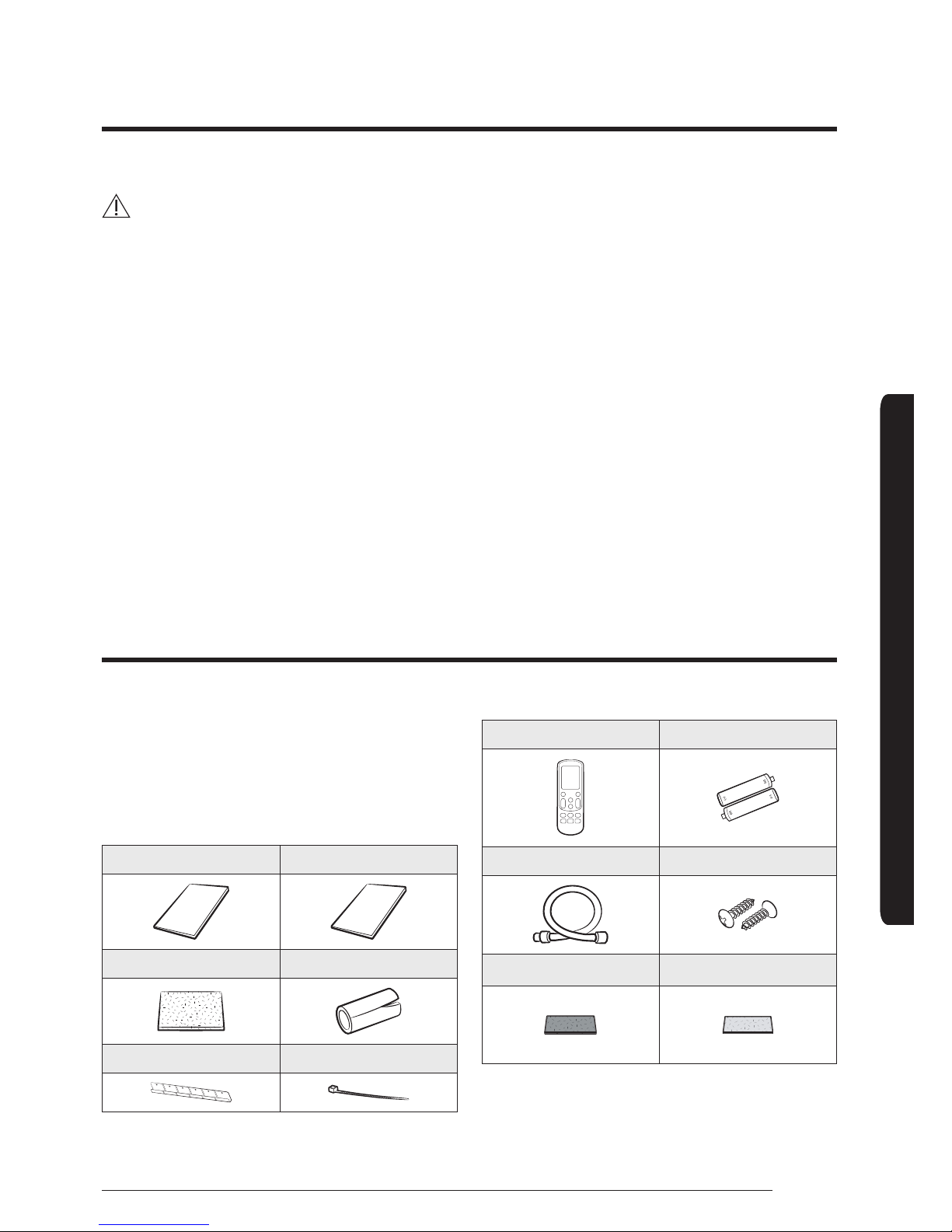
Step 1 Checking and preparing
accessories
The following accessories are supplied with the indoor
unit. The type and quantity may differ, depending on the
specifications.
User’s manual(1) Installation manual (1)
Insulation Install Outlet (1) Insulation Install SVC (1)
Bracket Hanger (1) Cable-tie (8)
Wireless remote control (1) Battery (2)
Drain Hose (1) M4x12 tapped screw(2)
Anti-allergy filter(1) Deodorizing filter(1)
Installation Procedure
6
Installation Procedure
Installation Procedure
English
Step 2 Choosing the installation
location
General requirements for installation location
Do not install the air conditioner in a location where it
will come into contact with the following elements:
• Combustible gases
• Saline air
• Machine oil
• Sulphide gas
• Special environmental conditions
Avoid installing the air conditioner in a location with the
following conditions:
• In areas where it is exposed to direct sunlight. Close
to heat sources.
• In damp areas or locations where it could come into
contact with water. (for example rooms used for
laundry)
• In areas where curtains and furniture could affect the
supply and discharge of air.
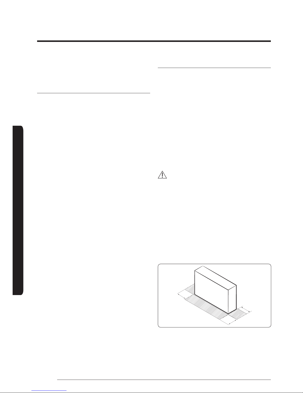
• Without leaving the required minimum space around
the unit. (as shown in the drawing)
• In scarcely ventilated areas.
• On surfaces that are unable to support the weight
of the unit without deforming, breaking or causing
vibrations during the use of the air conditioner.
• In a position that does not enable the condensate
drainage pipe to be correctly installed. (at the end
of the installation. It is always essential to check the
efficiency of the drainage system)
Indoor unit installation requirement
• This unit has to be installed as floor type only.
• There must be no obstacles near the air inlet and
outlet.
• Select a convenient location that permits the air to
reach every corner of the area to be cooled.
• Pre-plan for easy and short routing of the refrigerant
tubing and wiring to the outdoor unit.
• There should be no flammable gas, alkaline,
substances present in the air.
• Maintain sufficient clearance around the indoor unit.
• Make sure that the water dripping from the drain
hose runs away correctly and safely.
• Do not install the unit where it will be exposed to
direct sunlight.
CAUTION
• Our units should be installed in compliance with the
spaces shown in the installation manual, to ensure
accessibility from both sides and allow repairs
or maintenance operations to be carried out. The
unit’s components should be accessible and easy to
disassemble without endangering people and objects.
• For this reason, when provisions of the installation
manual are not complied with, the cost required to
access and repair the units (in SAFETY CONDITIONS,
as set out in prevailing regulations) with harnesses,
ladders, scaffolding or any other elevation system
will NOT be considered part of the warranty and will
be charged to the end customer.
A
A
A : 300mm or more
B : 1000mm or more
B
7
Installation Procedure
English
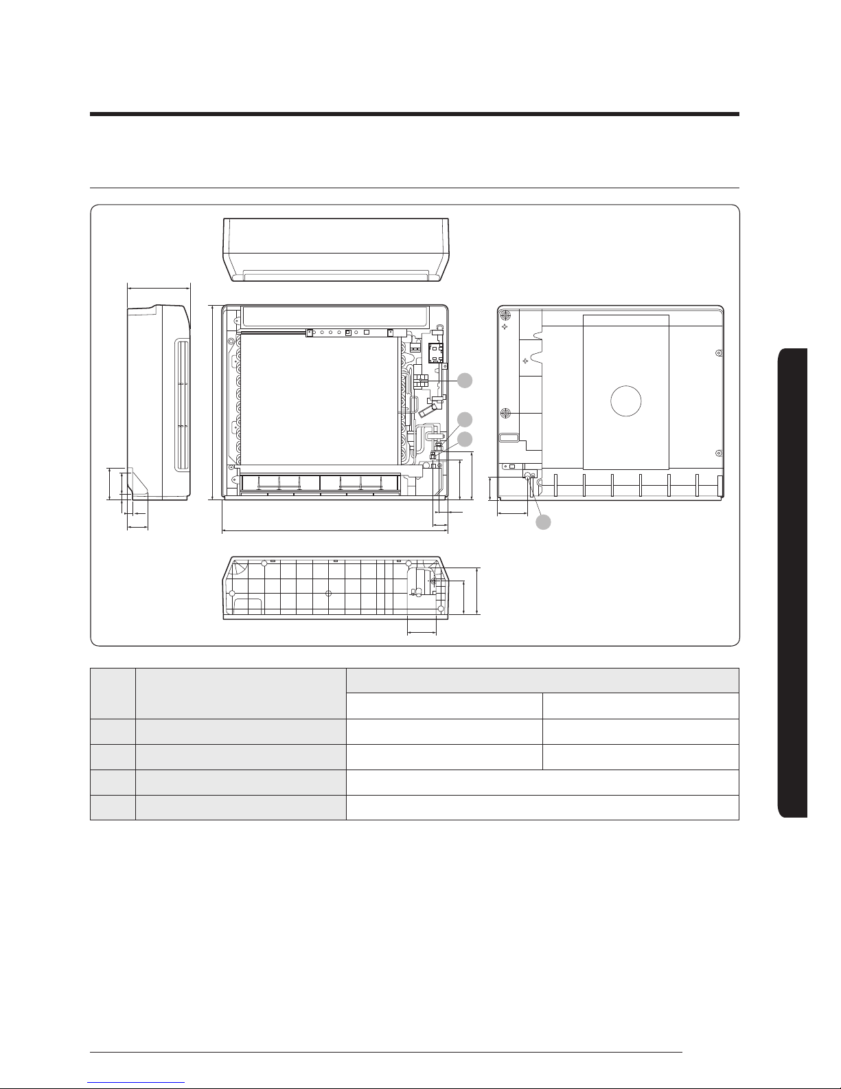
Indoor unit dimensions
199
16
65
720
30
96
48
89
103
6818
620
128
104
104
153
75
01
02
03
04
No. Name
MODEL
022 / 028 / 036
056
01 Liquid pipe connection Ø6.35(1/4") Ø6.35(1/4")
02
Gas pipe connection Ø9.52(3/8") Ø12.70(1/2")
03
Drainpipe connection ID : Ø12 ; OD : Ø18
04
Power supply connection 0.75~1.5mm², 3wires
8
Installation Procedure
Installation Procedure
English
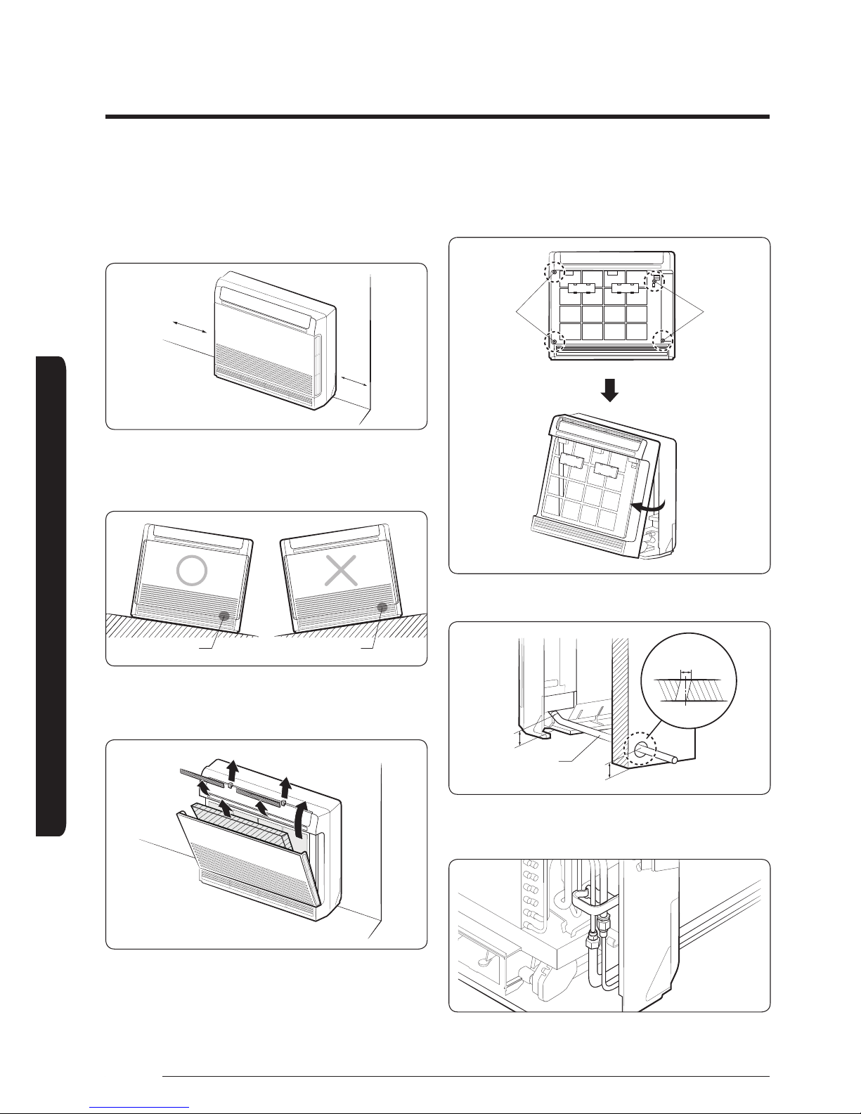
Step 3 Indoor unit installation
1 When you install the indoor with side-pipe
connection, please make space more than 300mm
from the wall.
A : 300 mm
A
A
2 When you install the indoor with side-pipe
connection, please make space more than 300mm
from the wall.
Position of drain Position of drain
3 Please remove the items when set is installed.
(
022/028/036: 6 Items / 056: 7 Items)
4 The body front should be opened to connect pipes.
Please release the 4 screws of body front and then
pull it out from the bottom of the set.
Screw Hole Screw Hole
5 Make a hole on the wall.
75 mm
75 mm
Drain hose
less than 70mm
Ø60~65mm
6 The pipes & cable should be gone through the bottom
back hole.
9
Installation Procedure
English
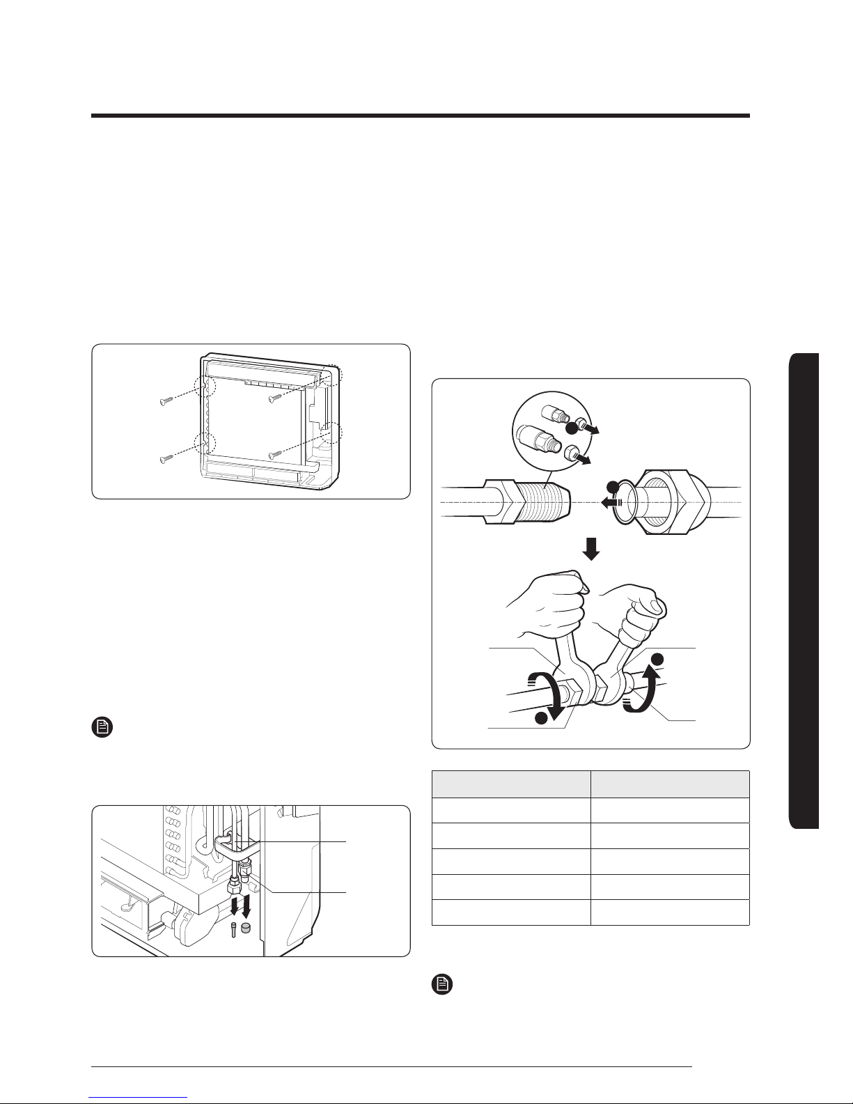
7 Hanging the indoor unit on the Bracket Hanger, then
fix the Indoor Unit by using 4 Screws.
• Case 1. Installing on the floor : Must fix 4 screws
on the wall, make the indoor not to fall down(For
safety installation) .
• Case 2. Hanging on the wall : Follow the
installation guide supplied in the accessory part.
– Screw positions are specified on the installation
guide.
Step 4 Purging inert gas from the
indoor unit
From factory the unit is supplied and set with a precharge of nitrogen gas (inert gas). Therefore, all inert gas
must be purged before connecting the assembly piping.
Unscrew the pinch pipe at the end of each refrigerant
pipe.
• Result: All inert gas escapes from the indoor unit.
NOTE
To prevent dirt or foreign objects from getting into the
pipes during installation, do NOT remove the pinch pipe
completely until you are ready to connect the piping.
Liquid
refrigerant
port
Gas
refrigerant
port
The designs and shape are subject to change according
to the model.
Step 5 Connecting the assembly
pipes to the refrigerant pipes
There are two refrigerant pipes of different diameters :
• A smaller one for the liquid refrigerant.
• A larger one for the gas refrigerant. The inside of
copper pipe must be clean and has no dust.
1 Remove the pinch pipe on the pipes and connect the
assembly pipes to each pipe, tightening the nuts, first
manually and then with a torque wrench, a spanner
applying the following torque.
2
3
3
1
Torque
wrench
Flare nut
Spanner
Union
Outer Diameter (mm) Torque (N•m)
Ø6.35 14 to 18
Ø9.52 34 to 42
Ø12.70 49 to 61
Ø15.88 68 to 82
Ø19.05 100 to 120
(1N•m=10kgf•cm)
NOTE
• If the pipes must be shortened, see Step 6 Cutting or
flaring the pipes on page 10.
10
Installation Procedure
Installation Procedure
English
2 Be sure to use an insulator thick enough to cover the
refrigerant tube to protect the condensate water on
the outside of the pipe falling onto the floor and to
improve the efficiency of the unit.
3 Cut off any excess foam insulation.
4 Make sure that there are no cracks or waves on the
bent area.
5 It would be necessary to double the insulation
thickness (10 mm or more) to prevent condensation
even on the insulator when if the installed area is
warm and humid.
6 Do not use joints or extensions for the pipes that
connect the indoor and outdoor unit. The only
permitted connections are those for which the units
are designed.
CAUTION
• Connect the indoor and outdoor units using pipes
with flared connections (not supplied). For the lines,
use insulated, unwelded, degreased and deoxidized
copper pipe (Cu DHP type to ISO 1337 or UNI
EN 12735-1), suitable for operating pressures of
at least 4200kPa and for a burst pressure of at
least 20700kPa. Copper pipe for hydro-sanitary
applications is completely unsuitable.
• For sizing and limits (height difference, line length,
max. bends, refrigerant charge, etc.) see the outdoor
unit installation manual.
• All refrigerant connection must be accessible, in order
to permit either unit maintenance or removing it
completely.
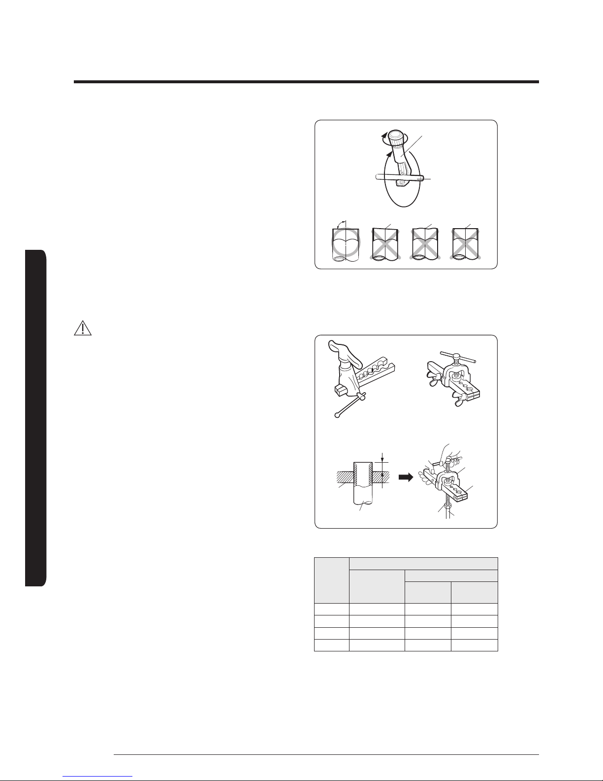
Step 6 Cutting or flaring the pipes
1 Make sure that you prepared the required tools.
(pipe cutter, reamer, flaring tool and pipe holder)
2 If you want to shorten the pipe, cut it using a pipe
cutter ensuring that the cut edge remains at 90° with
the side of the pipe. There are some examples of
correctly and incorrectly cut edges below.
Pipe cutter
Pipe
Oblique
90°
Rough Burr
3 To prevent a gas leak, remove all burrs at the cut
edge of the pipe using a reamer.
4 Carry out flaring work using flaring tool as shown
below.
<Flaring tool>
Clutch type
Die
Copper pipe Flare nut Copper pipe
York
Die
A
Wing nut type
(Unit: mm)
Outer
diameter
A
Flare tool for
R410A clutch
type
Conventional flare tool
Clutch type
Wing nut
type
6.35 0~0.5 1.0~1.5 1.5~2.0
9.52 0~0.5 1.0~1.5 1.5~2.0
12.70 0~0.5 1.0~1.5 1.5~2.0
15.88 0~0.5 1.0~1.5 1.5~2.0
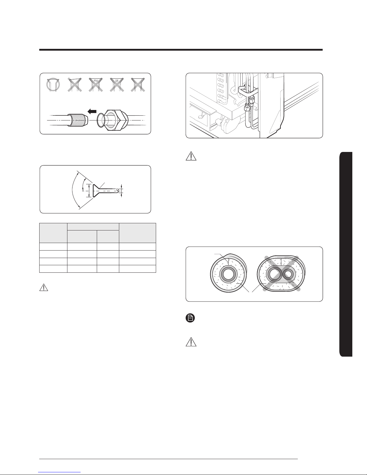
5 Check if you flared the pipe correctly. There are some
examples of incorrectly flared pipes below.
11
Installation Procedure
English
Inclined Damaged
Surface
Cracked Uneven
Thickness
6 Align the pipes and tighten the flare nuts first
manually and then with a torque wrench, applying
the following torque.
R 0.4~0.8
90°±2°
45°±2°
L
D
Outer
diameter (D,
mm)
Connection Torque
Flare dimension
(L, mm)
kgf•cm N•m
6.35 140~180 14~18 8.70~9.10
9.52 350~430 34~42 12.80~13.20
2.70 500~620 49~61 16.20~16.60
15.88 690~830 68~82 19.30~19.70
CAUTION
In case of needing brazing, you must work with nitrogen
gas blowing.
Step 7 Performing the gas leak test
To identify potential gas leaks on the indoor unit, inspect
the connection area of each refrigerant pipe using a leak
detector for R-410A.
Before recreating the vacuum and recirculating the
refrigerant gas, pressurize the whole system with
nitrogen (using a cylinder with a pressure reducer) at a
pressure above 4 MPa in order to immediately detect
leaks on the refrigerant fittings.
Made vacuum for 15 minutes and pressurizing system
with nitrogen.
CAUTION
• If the pipes require brazing ensure that OFN (Oxygen
Free Nitrogen) is flowing through the system.
Step 8 Insulating the refrigerant
pipes
Once you have checked that there are no leaks in the
system, you can insulate the piping and hose.
1 To avoid condensation problems, place Acrylonitrile
Butadien Rubber separately around each refrigerant pipe.
No gap
NBR
NOTE
• Always make the seam of pipes face upwards.
CAUTION
• The insulation has to be produced in full compliance
of European regulation reg. EEC / EU 2037/ 2000
that requires the use of sheaths insulation form
without using CFC and HCFC gases for health and the
environment.
2 Wind insulating tape around the pipes and drain hose
avoiding compressing the insulation too much.
 Loading...