

Samsung AE022MNADEH, AE028MNADEH, AE056MNADEH, AE071MNADEH Installation Manual
Air conditioner
Installation manual
AE
MNADEH
• Thank you for purchasing this Samsung air conditioner.
• Before operating this unit, please read this Installation manual carefully and retain it for future
reference.

2
English
Contents
Installation 3
Safety Information on Installation 3
Preparation 5
Step 1.1 Choosing the installation location
Step 1.2 Checking and preparing accessories and tools
Step 1.3 Drilling a hole through the wall
Step 1.4 Performing leak test
Step 1.5 Wrapping the pipes with the insulation
Indoor Unit Installation 8
Step 2.1 Disassembling the cover panel
Step 2.2 Disassembling the installation plate
Step 2.3 Connecting the power and communication cables
Step 2.4 Optional: Extending the power cable
Step 2.5 Installing the drain hose
Step 2.6 Optional: Extending the drain hose
Step 2.7 Optional: Changing the direction of the drain hose
Step 2.8 Purging the unit
Step 2.9 Connecting the refrigerant pipe
Step 2.10 Cutting or flaring the pipes
Step 2.11 Fixing the installation plate
Step 2.12 Fixing the indoor unit to the installation plate
Step 2.13 Assembling the cover panel
Setting an indoor unit address and installation option 19
Troubleshooting 33
For information on Samsung’s environmental commitments and product specific regulatory
obligations e.g. REACH visit: samsung.com/uk/aboutsamsung/samsungelectronics/
corporatecitizenship/data_corner.html

3
English
Installation
Carefully follow the precautions listed below because
they are essential to guarantee the safety of both the air
conditioner and the workers.
• Always disconnect the air conditioner from the power
supply before servicing it or accessing its internal
components.
• Verify that installation and testing operations are
performed by qualified personnel.
• Verify that the air conditioner is not installed in an
easily accessible area.
General information
• Carefully read the content of this manual before
installing the air conditioner and store the manual in
a safe place in order to be able to use it as reference
after installation.
• For maximum safety, installers should always carefully
read the following warnings.
• Store the operation and installation manual in a safe
location and remember to hand it over to the new
owner if the air conditioner is sold or transferred.
• This manual explains how to install an indoor unit
with a split system with two SAMSUNG units. The use
of other types of units with different control systems
may damage the units and invalidate the warranty.
The manufacturer shall not be responsible for damages
arising from the use of non compliant units.
• The manufacturer shall not be responsible for damage
originating from unauthorised changes or the improper
connection of electric and requirements set forth in the
“Operating limits” table, included in the manual, shall
immediately invalidate the warranty.
• The air conditioner should be used only for the
applications for which it has been designed: the indoor
unit is not suitable to be installed in areas used for
laundry.
• Do not use the units if damaged. If problems occur,
switch the unit off and disconnect it from the power
supply.
• In order to help prevent electric shocks, fires or
injuries, always stop the unit, disable the protection
switch and contact SAMSUNG’s technical support if
the unit produces smoke, if the power cable is hot or
damaged or if the unit is very noisy.
• Always remember to inspect the unit, electric
connections, refrigerant tubes and protections
regularly. These operations should be performed by
qualified personnel only.
• The unit contains moving parts, which should always
be kept out of the reach of children.
• Do not attempt to repair, move, alter or reinstall the
unit. If performed by unauthorised personnel, these
operations may cause electric shocks or fires.
• Do not place containers with liquids or other objects
on the unit.
• All the materials used for the manufacture and
packaging of the air conditioner are recyclable.
• The packing material and exhaust batteries of the
remote control (optional) must be disposed of in
accordance with current laws.
• The air conditioner contains a refrigerant that has
to be disposed of as special waste. At the end of its
life cycle, the air conditioner must be disposed of in
authorised centres or returned to the retailer so that it
can be disposed of correctly and safely.
Installation of the unit
• IMPORTANT: When installing the unit, always
remember to connect first the refrigerant tubes, then
the electrical lines. Always disassemble the electric
lines before the refrigerant tubes.
• Upon receipt, inspect the product to verify that it has
not been damaged during transport. If the product
appears damaged, DO NOT INSTALL it and immediately
report the damage to the carrier or retailer (if the
installer or the authorised technician has collected the
material from the retailer.)
• After completing the installation, always carry out a
functional test and provide the instructions on how to
operate the air conditioner to the user.
• Do not use the air conditioner in environments with
hazardous substances or close to equipment that
release free flames to avoid the occurrence of fires,
explosions or injuries.
• Our units must be installed in compliance with the
spaces indicated in the installation manual to ensure
either accessibility from both sides or ability to
perform routine maintenance and repairs. The units’
components must be accessible and that can be
disassembled in conditions of complete safety either
for people or things. For this reason, where it is not
observed as indicated into the Installation Manual, the
cost necessary to reach and repair the unit (in safety,
as required by current regulations in force) with slings,
Safety Information on Installation
4
English
Installation
trucks, scaffolding or any other means of elevation
won’t be considered in-warranty and will be charged
to end user.
Power supply line, fuse, or circuit
breaker
• Always make sure that the power supply is compliant
with current safety standards. Always install the air
conditioner in compliance with current local safety
standards.
• Always verify that a suitable grounding connection is
available.
• Verify that the voltage and frequency of the power
supply comply with the specifications and that the
installed power is sufficient to ensure the operation of
any other domestic appliance connected to the same
electric lines.
• Always verify that the cut-off and protection switches
are suitably dimensioned.
• Verify that the air conditioner is connected to the
power supply in accordance with the instructions
provided in the wiring diagram included in the manual.
• Always verify that electric connections (cable entry,
section of leads, protections…) are compliant with
the electric specifications and with the instructions
provided in the wiring scheme. Always verify that all
connections comply with the standards applicable to
the installation of air conditioners.
• Devices disconnected from the power supply should
be completely disconnected in the condition of
overvoltage category.
CAUTION
• Make sure that you earth the cables.
- Do not connect the earth wire to the gas pipe, water
pipe, lighting rod or telephone wire. If earthing is not
complete, electric shock or fire may occur.
• Install the circuit breaker.
- If the circuit breaker is not installed, electric shock or
fire may occur.
• Make sure that the condensed water dripping from the
drain hose runs out properly and safely.
• Install the power cable and communication cable of
the indoor and outdoor unit at least 1m away from the
electric appliance.
• Install the indoor unit away from lighting apparatus
using the ballast.
- If you use the wireless remote controller, reception
error may occur due to the ballast of the lighting
apparatus.
• Do not install the air conditioner in following places.
- Place where there is mineral oil or arsenic acid. Resin
parts flame and the accessories may drop or water
may leak. The capacity of the heat exchanger may
reduce or the air conditioner may be out of order.
- The place where corrosive gas such as sulfurous acid
gas generates from the vent pipe or air outlet.
• The copper pipe or connection pipe may corrode and
refrigerant may leak.
- The place where there is a machine that generates
electromagnetic waves. The air conditioner may not
operate normally due to control system.
- The place where there is a danger of existing
combustible gas, carbon fiber or flammable dust.
• The place where thinner or gasoline is handled. Gas
may leak and it may cause fire.
• Be sure not to perform power cable modification,
extension wiring, and multiple wire connection.
- It may cause electric shock or fire due to poor
connection, poor insulation, or current limit override.
- When extension wiring is required due to power line
damage, refer to "Step 2.4 Optional:Extending the
power cable" in the installation manual.
Safety Information on Installation
5
English
Installation
Preparation
Step 1.1 Choosing the installation
location
Overview of installation location requirements
CAUTION
Step 1.2 Checking and preparing
accessories and tools
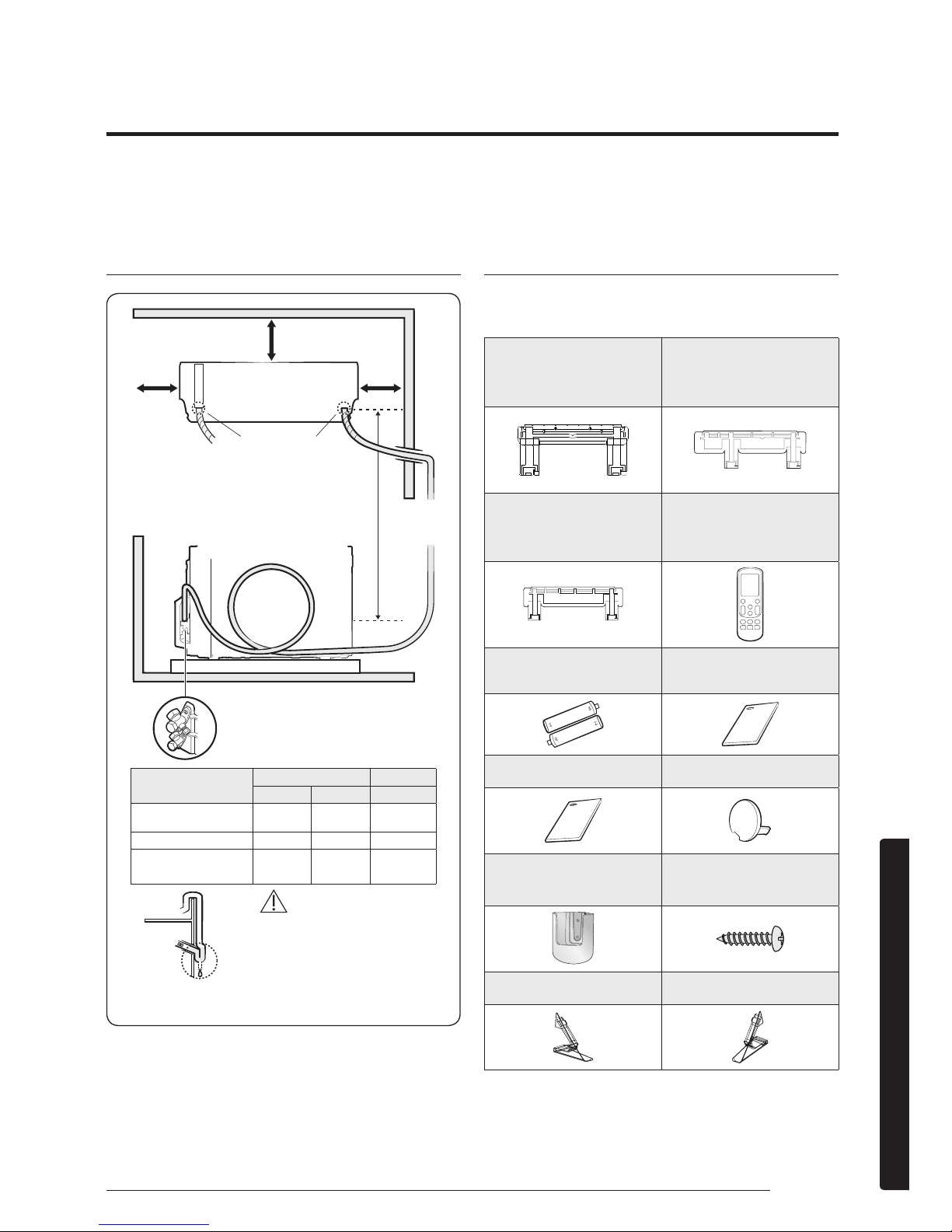
Accessories
Accessories in the indoor unit package
Installation plate (1)
022/028
(01 frame)
Installation plate (1)
036
(03 frame)
Installation plate (1)
056/071
(05 frame)
Remote control (1)
Remote control battery (2) User Manual (1)
Installation Manual (1) Cap screw (3)
Remote Control Holder (1)
M4 x 16
Tapped Screws (2)
Guide Left(1) Guide Right(1)
100 mm or more
(recommended)
125 mm
or more
(recommended)
125 mm
or more
(recommended)
Drain hose hole
You can select the direction of
draining (left or right).
Make at least one round to
reduce noise and vibration.
The actual units may look different from
the images depicted here.
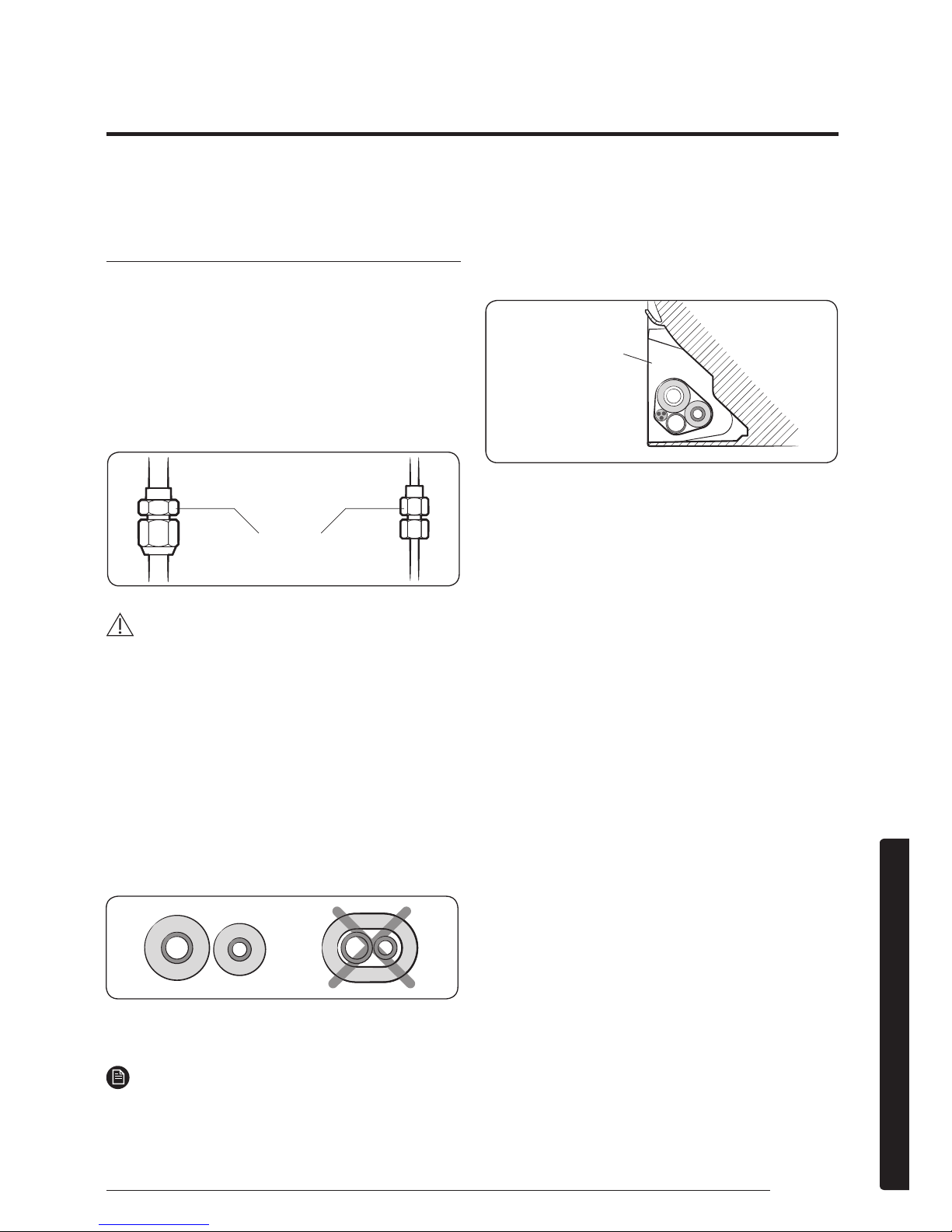
Make a U-trap (A) on the
pipe (which is connected to
the indoor unit) at outer wall
and cut the bottom part of
the insulation (about 10 mm)
to prevent rainwater from
getting inside through the
insulation.
Outdoor
Unit
Outer wall
Indoor
Unit
Cut insulation to have
rainwater drained
(Unit : m)
Model
Pipe length Pipe height
Minimum Maximum Maximum
AE022MNADEH
AE028MNADEH
3 20 15
AE036MNADEH 3 30 20
AE056MNADEH
AE071MNADEH
3 50 30
6
English
Installation
Tools
General tools
• Vacuum pump
(Backward flowing
prevention)
• Manifold gauge
• Stud finder
• Torque wrench
• Pipe cutter
• Reamer
• Pipe bender
• Spirit level
• Screwdriver
• Spanner
• Drill
• L-wrench
• Measuring tape
Tools for test operation
• Thermometer
• Resistance meter
• Electroscope
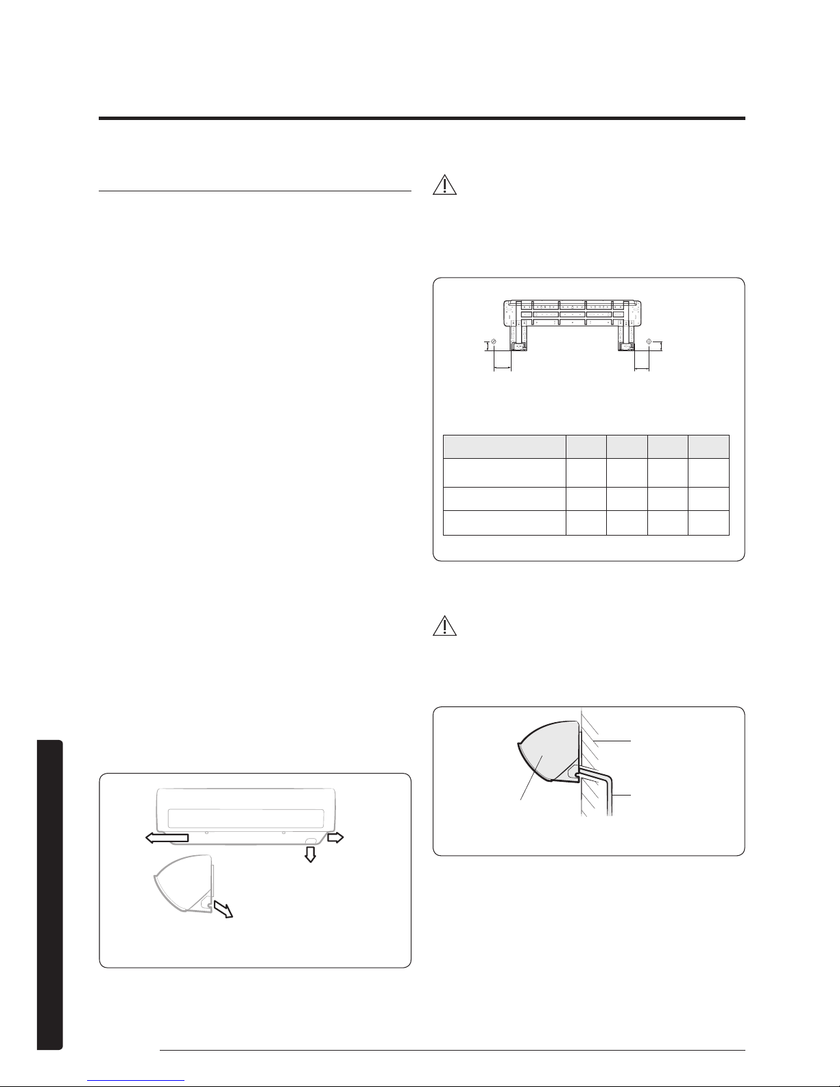
Step 1.3 Drilling a hole through the
wall
Before fixing the installation plate to a wall and then fixing
the indoor unit to the installation plate, a window frame,
or a gypsum board, you must determine the position of a
hole (with 65 mm inner diameter) through which the pipe
bundle (consisting of power and communication cables,
refrigerant pipes, and drain hose) will pass and then drill
that hole.
1 Determine the position of a 65 mm hole in
consideration of the possible directions of the pipe
bundle and the minimum distances between the hole
and the installation plate.
CAUTION
• If changing the pipe direction from left to right, do not
drastically bent it but slowly turn it in the opposite
direction as shown. Otherwise, the pipe may be
damaged in the process.
2 Drill the hole.
CAUTION
• Be sure to drill only one hole.
• Make sure that the hole slants downwards so that the
drain hose slants downwards to drain water well.
<Possible directions of the pipe bundle>
Left Right
Rear right or left
Bottom right
(Unit : mm)
Model A B C D
AE022MNADEH
AE028MNADEH
36 60 65 36
AE036MNADEH 36 120 81 36
AE056MNADEH
AE071MNADEH
33 110 110 33
Pipe bundle hole: Ø 65 mm
<Minimum distances between the hole and the
installation plate>
B
A
D
C
Pipe bundle hole
Wall
Drain hose
Indoor unit
<The hole slants downwards>
Preparation
7
English
Installation
Step 1.4 Performing leak test
Leak test
LEAK TEST WITH NITROGEN (before opening valves)
In order to detect basic refrigerant leaks, before recreating
the vacuum and recirculating the R410A, it’s responsible of
installer to pressurize the whole system with nitrogen (using
a pressure regulator) at a pressure above 4.1MPa (gauge).
LEAK TEST WITH R410A (after opening valves)
Before opening valves, discharge all the nitrogen into the
system and create vacuum. After opening valves check
leaks using a leak detector for refrigerant R410A.
Test parts for the
indoor unit
CAUTION
• Discharge all the nitrogen to create a vacuum and
charge the system.
Step 1.5 Wrapping the pipes with the
insulation
After checking for gas leaks in the system, insulate the
pipe, hose and cables. Then place the indoor unit on the
installation plate.
1 To avoid condensation problems, place heat-resistant
poly-ethylene foam separately around each refrigerant
pipe in the lower part of the indoor unit.
2 Wrap the refrigerant pipe and the drain hose in the
rear of the indoor unit with the absorbent pad.
NOTE
• Wind the pipe and hose three times to the end of the
indoor unit with the absorbent pad. (20mm interval)
3 Wind the pipe, assembly cable and drain hose with
insulation tape.
4 Place the bundle (the pipe, assembly cable and drain
hose) in the lower part of the indoor unit carefully so it
doesn’t project from the rear of the indoor unit.
Installation plate
5 Hook the indoor unit to the installation plate and move
the unit to the right and left until it is securely in place.
6 Wrap the rest of the pipe with vinyl tape.
7 Attach the pipe to the wall using clamps (optional).
8
English
Installation
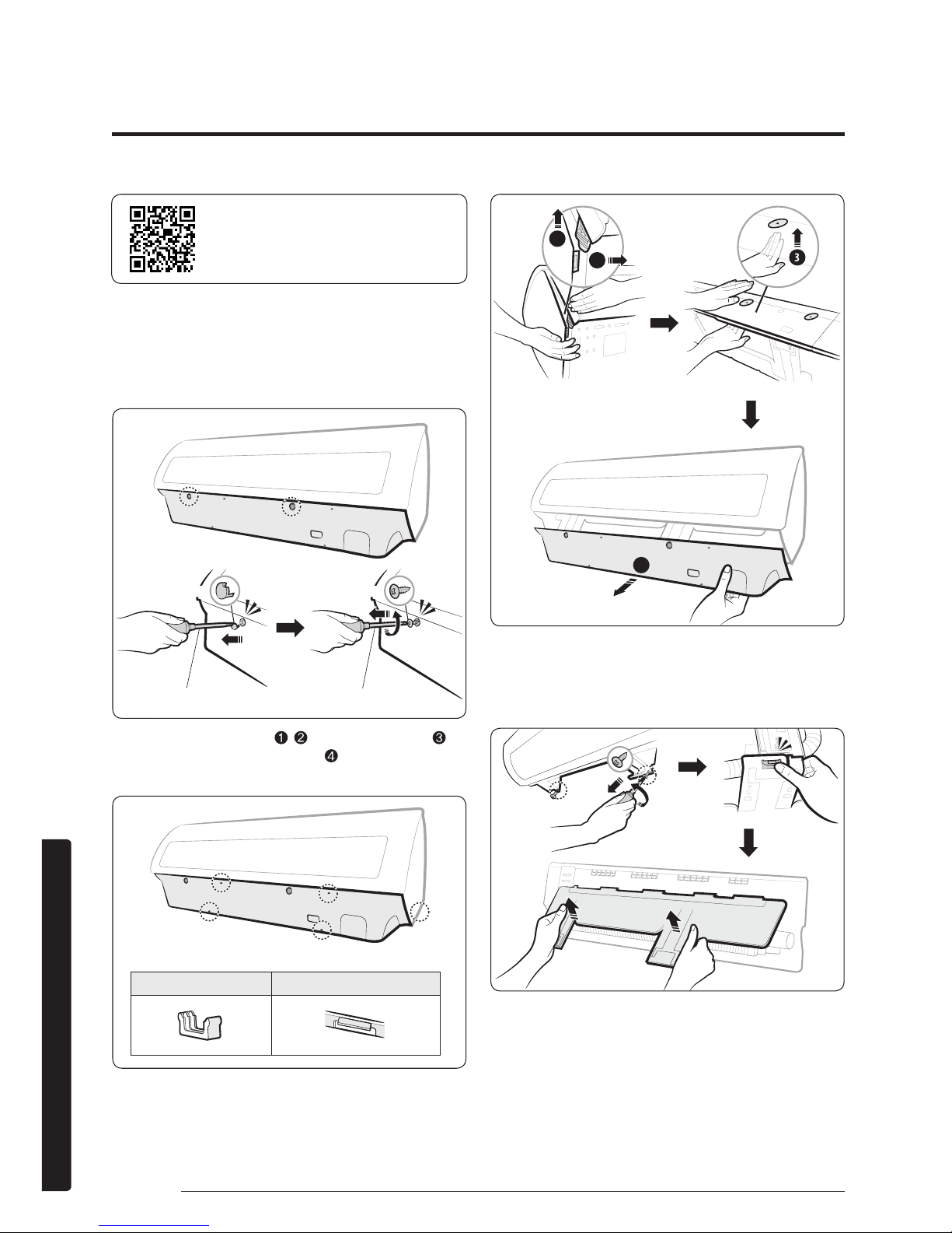
Step 2.1 Disassembling the cover
panel
1 Remove the cap screws, then the screws.
2 Unlock the side hooks ( , ), then centre hooks ( ).
Then unlock the bottom hooks ( ) to pull out the
cover panel.
B
B
C
A
A
1
2
4
Step 2.2 Disassembling the
installation plate
Indoor Unit Installation
Please scan this QR code for detail
video of indoor unit installation.
Cap screw
Phillips screwdriver
Screw
Flat-head screwdriver
Centre hook (A) Bottom/Side hook (B/C)
9
English
Installation
Step 2.3 Connecting the power and
communication cables
1 Before wiring work, you must turn off all power
source.
2 Indoor unit power should be supplied through the
breaker( ELCB or MCCB+ELB ) separated by the
outdoor power.
• ELCB:Earth Leakage Circuit Breaker
• MCCB:Molded Case Circuit Breaker
• ELB:Earth Leakage Breaker
3 The power cable should be used only copper wires.
4 Connect the power cable{1(L), 2(N)} among the units
within maximum length and communication cable(F1,
F2) each.
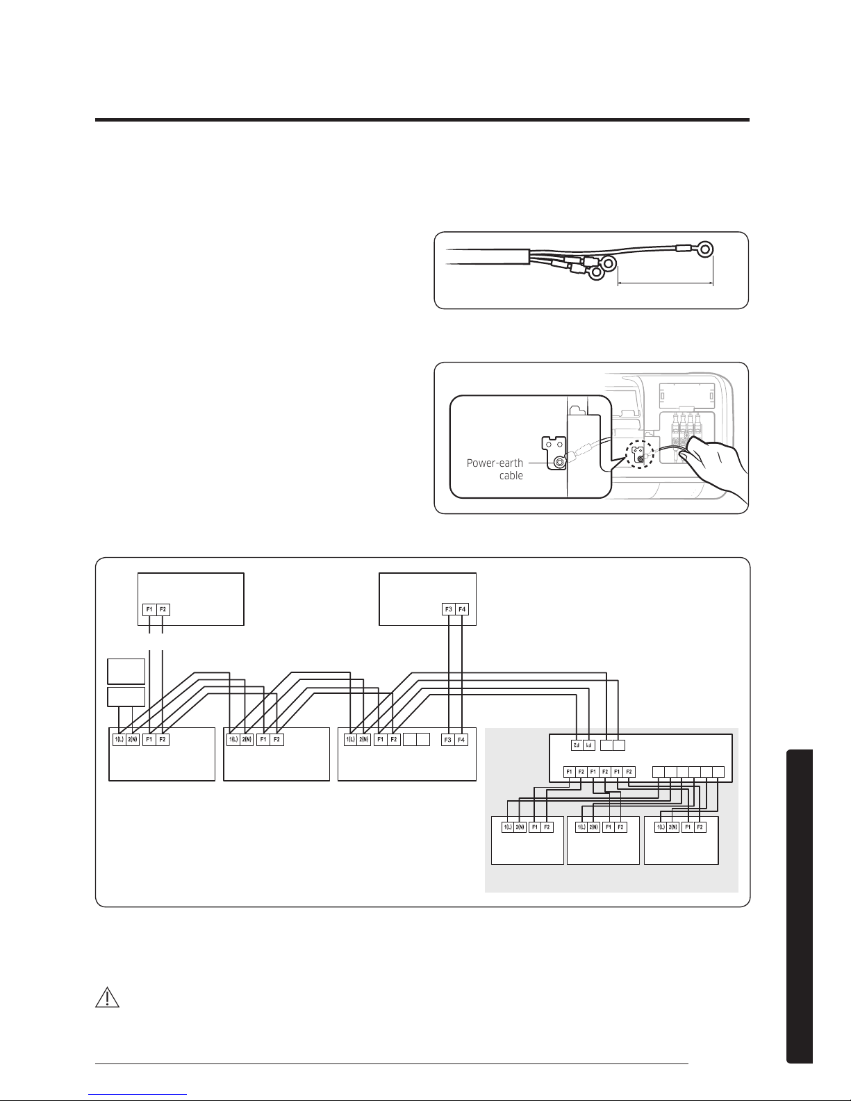
5 Cut the cable as like the following picture. The earth
cable need to be longer than the power cable (1(L),
2(N)) by 100 mm.
100mm
6 Connect the earth cable to the plate on the evaporator
as like the following picture.
Power-earth
cable
Control box
7 Connect F3, F4(for communication) wires when installing the wired remote control.
N L
N L N L N L
ELCB
MCCB+
ELB
V1 V2
Outdoor Unit
Indoor Unit 1 Indoor Unit 2 Indoor Unit 3
Indoor Unit 4 Indoor Unit 5 Indoor Unit 6
EEV kit
220-240V~or
Wired Remote
Control
∙ Ceiling, wall-mounted indoor unit.
• ELCB : Essential Installation
• EEV KIT : Required installation. It is not included inside of product. Install distribution kit for 1, 2 or 3 rooms on the
ceiling or outdoor area.
WARNING
• Power off before connecting any wires;Indoor PBA will be damaged while V1,V2,F3,F4 short each other.
• You must connect the earth cable. If earthing is not complete, electric shock or fire may occur.
10
English
Installation
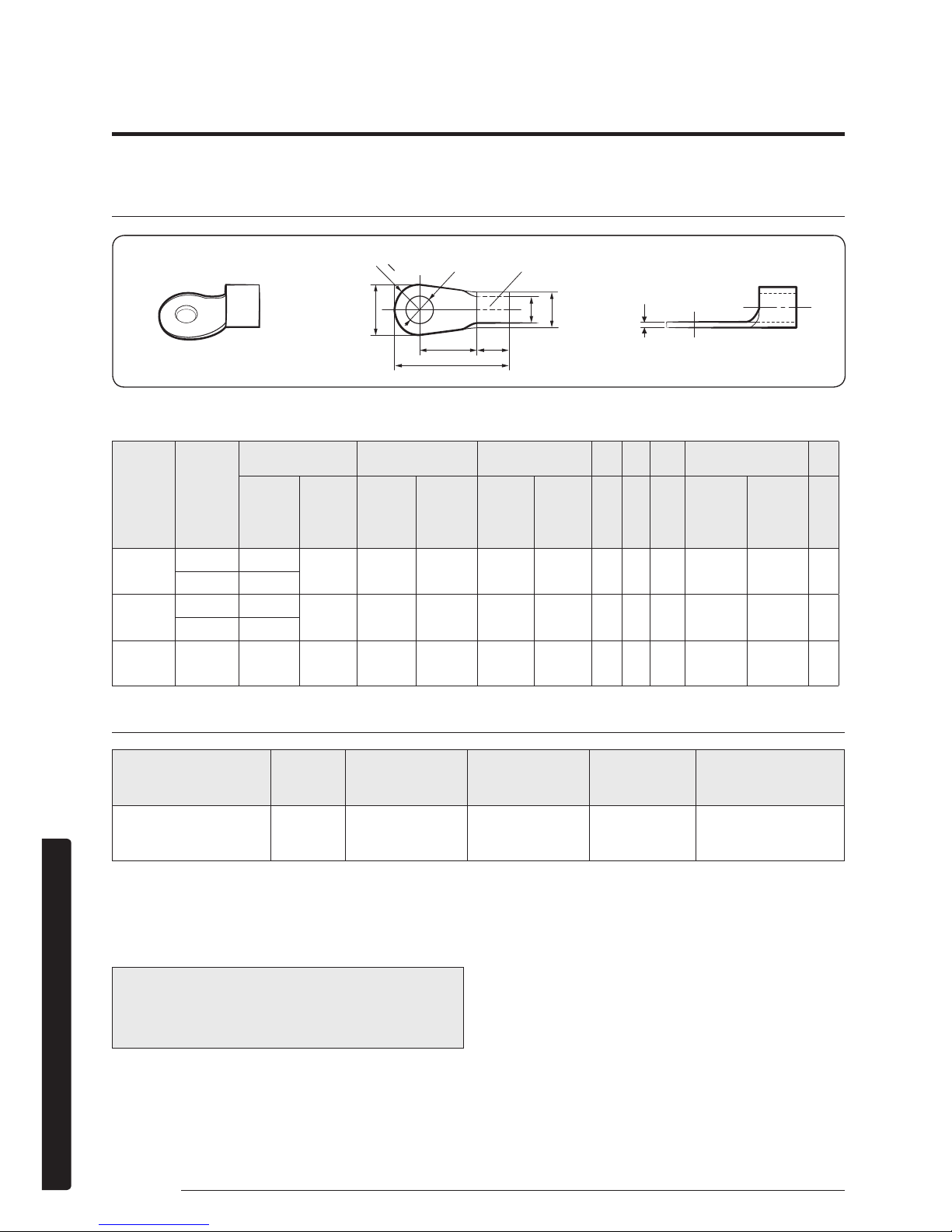
Ring terminal selection
t
R
B
2
d2
d1
D
B
L
F E
Silver solder
Norminal
dimensions
for cable
(mm2)
Norminal
dimensions
for screw
(mm)
B C d1 E F L d2 t
Standard
dimension
(mm)
Allowance
(mm)
Standard
dimension
(mm)
Allowance
(mm)
Standard
dimension
(mm)
Allowance
(mm)
Min. Min. Max.
Standard
dimension
(mm)
Allowance
(mm)
Min.
1.5
4 6.6
±0.2 3.4
+0.3
-0.2
1.7 ±0.2 4.1 6 16 4.3
+0.2
0
0.7
4 8
2.5
4 6.6
±0.2 4.2
+0.3
-0.2
2.3 ±0.2 6 6 17.5 4.3
+0.2
0
0.8
4 8.5
4 4 9.5 ±0.2 5.6
+0.3
-0.2
3.4 ±0.2 6 5 20 4.3
+0.2
0
0.9
Specification of electronic wire
Power supply MCCB ELB or ELCB Power cable Earth cable
Communication
cable
Max : 242V / Min :
198V
XA
XA, 30mmA,
0.1 s
2.5mm 2.5mm 0.75~1.5mm
• Refer to the unit nameplate for rating current.
• Decide the capacity of ELCB(or MCCB+ELB) by below formula.
• Power supply cords of parts of appliances for outdoor use shall not be lighter than polychloroprene sheathed flexible
cord.
(Code designation IEC:60245 IEC 57 / CENELEC: H05RN-F or IEC:60245 IEC 66 / CENELEC: H07RN-F )
The capacity of ELCB(or MCCB+ELB) X[A] = 1.25 X 1.1 X ∑Ai
– X : The capacity of ELCB(or MCCB+ELB).
– ∑Ai : Sum of Rating currents of each indoor unit.
– Refer to each installation manual about the rating
current of indoor unit.
• Decide the power cable specification and maximum length within 10% power drop among indoor units.
Indoor Unit Installation
11
English
Installation
n
Coef×35.6×Lk×ik
) <
10% of input
voltage[V]
– coef: 1.55
– Lk: Distance among each indoor unit[m],
Ak: Power cable specification[mm]
ik: Running current of each unit[A]
∑ (
1000×Ak
k=1
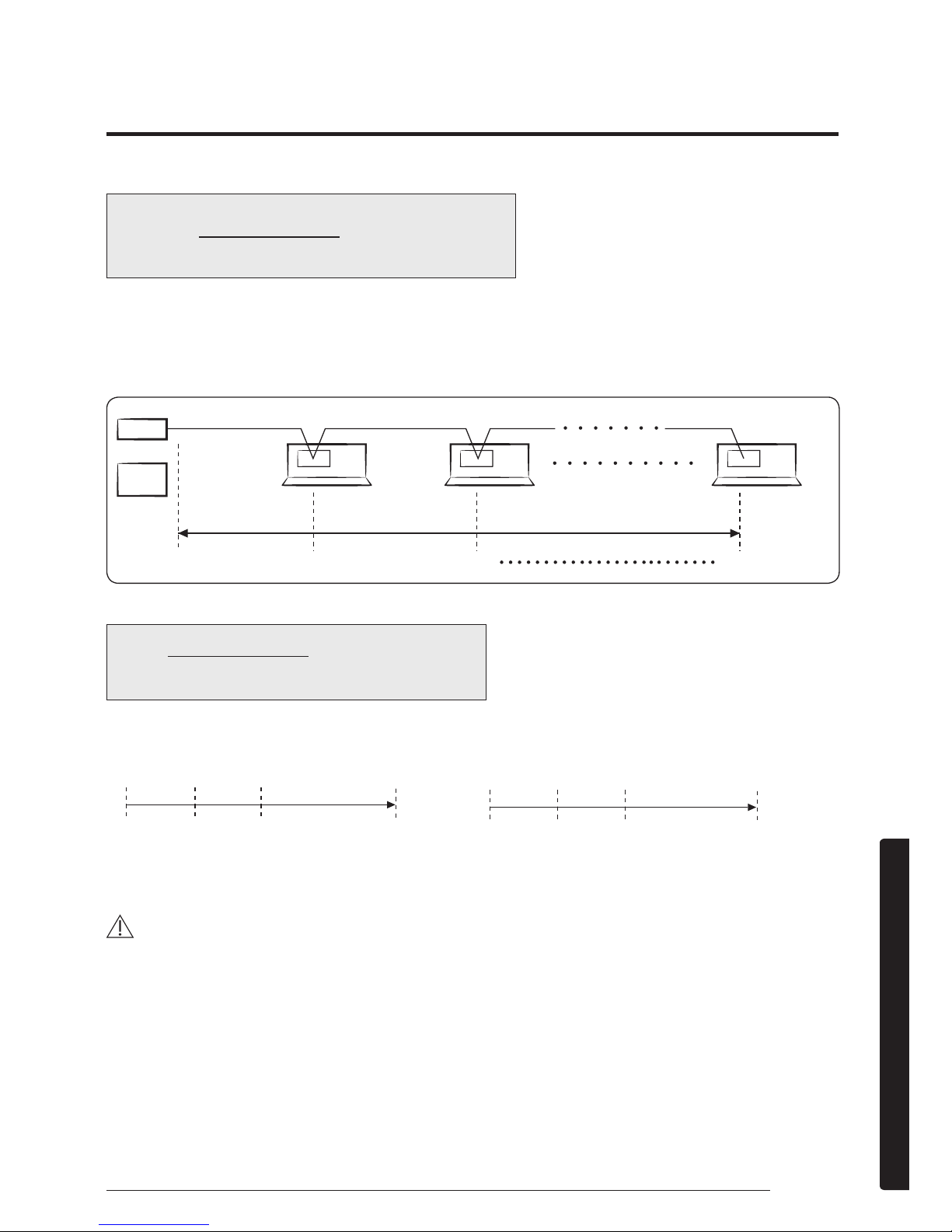
Example of Installation
– Total power cable length L = 100(m), Running current of each units 1[A]
– Total 10 indoor units were installed
ELCB
0[m] 10[m] 20[m] 100[m]
9[A]10[A]
Indoor unit1 Indoor unit2 Indoor unit10
1[A]
or
MCCB+
ELB
• Apply following equation.
n
Coef×35.6×Lk×ik
) <
10% of input
voltage[V]
∑ (
1000×A
k
k=1
• Calculation
– Installing with 1 sort wire – Installing with 2 different sort wire.
2.5 [mm2]
2.5 [mm
2
]
-2.2 [V] -2.0 [V]
220 [V]
-(2.2+2.0+1.8+1.5+1.3+1.1+0.9+0.7+0.4+0.2)=-11.2 [V]
208.8 [V] : it's okay
Within 198V
to 242V
······· 2.5 [mm2] ·······
4.0 [mm2]
4.0 [mm
2
]
-1.4 [V] -1.2 [V]
220 [V]
-(1.4+1.2+1.8+1.5+1.3+1.1+0.9+0.7+0.4+0.2)=-10.5 [V]
209.5 [V] : it's okay
Within 198V
to 242V
······· 2.5 [mm2] ·······
CAUTION
• Select the power cable in accordance with relevant local and national regulations.
• Wire size must comply with local and national code.
• For the power cable, use the grade of H07RN-F or H05RN-F materials.
• You should connect the power cable into the power cable terminal and fasten it with a clamp.
• The unbalanced power must be maintained within 10% of supply rating among whole indoor units.
• If the power is unbalanced greatly, it may shorten the life of the condenser. If the unbalanced power is exceeded over
10% of supply rating, the indoor unit is protected, stopped and the error mode indicates.
• To protect the product from water and possible shock, you should keep the power cable and the connection cord of
the indoor and outdoor units in the iron pipe.
• Connect the power cable to the auxiliary circuit breaker. An all pole disconnection from the power supply must be
incorporated in the fixed wiring(≥3mm).
 Loading...