

Samsung AC071MN4PKH, AC090MN4PKH, AC140MN4PKH, AC090MXADKH, AC100MXAD*H Service Manual
...
1. Precautions
2. Product Specifications
3. Disassembly and Reassembly
4. Troubleshooting
5. PCB Diagram
6. Wiring Diagram
7. Reference Sheet
CONTENTSSYSTEM AIR CONDITIONER
INDOOR UNIT OUTDOOR UNIT
SYSTEM AIR
CONDITIONER
CIRCULAR CASSETTE SERIES
AC071MN4PKH
AC090MN4PKH
AC100MN4PKH
AC120MN4PKH
AC140MN4PKH
AC090MXADKH
AC100MXAD*H
AC120MXAD*H
AC140MXAD*H

Section 0
1
Contents
1. Precautions
..............................................................................................................................................................................................
1-1
1-1. Precautions for the Service
.........................................................................................................................................................
1-1
1-2. Precautions related to static electricity and PL
...................................................................................................................
1-1
1-3. Precautions related to product safety
...................................................................................................................................
1-2
1-4. Other precautions
..........................................................................................................................................................................
1-2
2. Product Specifications
....................................................................................................................................................................
2-1
2-1. The Feature of Product
.................................................................................................................................................................
2-1
2-2. Product Specifications
..................................................................................................................................................................
2-2
2-3. Specifications of optional items
...............................................................................................................................................
2-8
2-3-1. Accessories
...........................................................................................................................................................................
2-8
2-3-2. Wireless remote controller (AR-KH0O)
.....................................................................................................................
2-9
2-3-3. Wired remote controller (AWR-WE10N)
..................................................................................................................
2-10
2-3-4. Filter specifications
............................................................................................................................................................
2-11
3. Disassembly and Reassembly
..................................................................................................................................................
3-1
3-1. Necessary Tools
...............................................................................................................................................................................
3-1
3-2. Indoor Unit
........................................................................................................................................................................................
3-2
3-3. Outdoor Unit
.....................................................................................................................................................................................
3-11
4.
Troubleshooting
..........................................................................................................................................................................
4-1
4-1. Setting an indoor unit address and installation option
..................................................................................................
4-1
4-1-1. The procedure of setting option
..................................................................................................................................
4-1
4-1-2. The procedure of setting option
.................................................................................................................................
4-2
4-1-3. Order for Setting Options (Wired Remote Controller)
........................................................................................
4-12
4-1-4. Indoor address(MAIN/RMC)setting
............................................................................................................................
4-13
4-1-5. Set the indoor installation options(Option to set for the installation site conditions)
...........................
4-14
4-1-6. Changing the addresses and options individually
...............................................................................................
4-15
4-2. Model-specific option code
............................................................................................................................................................
4-16
4-3. Diagnostic Checklist ago
..............................................................................................................................................................
4-17
4-3-1. Test operation mode and check mode
....................................................................................................................
4-17
4-3-2. Eco Mode [Power Save Mode]
......................................................................................................................................
4-18
4-3-3.
Error code [indoor]
...........................................................................................................................................................
4-19
4-3-4. Error code [outdoor]
..........................................................................................................................................................
4-20
4-3-5.Wired remote controller
..................................................................................................................................................
4-33
4-4. Troubleshooting by symptoms
...................................................................................................................................................
4-25
4-1-1. When the outdoor unit power is not ON – Initial Diagnosis : 1-phase products
....................................
4-25
4-4-2. Indoor temperature sensor error (E121)
..................................................................................................................
4-26
4-4-3. Indoor heat exchanger temperature sensor error (E122)
..................................................................................
4-27
4-4-4. Indoor Fan error (E154)
....................................................................................................................................................
4-28
4-4-5. Communication error after finishing Tracking (E202)
.........................................................................................
4-29
4-4-6. Indoor unit float sensor error
........................................................................................................................................
4-30
4-4-7. EEPROM circuit failure (E162)
........................................................................................................................................
4-31
4-4-8. The whistling noise from the indoor unit in low wind mode
..........................................................................
4-32
4-4-9. When the outdoor unit power is not ON - Initial Diagnosis : 3-phase products
.....................................
4-33
4-4-10. Indoor/outdoor communication error (1min.) (Error Code : E202)
............................................................
4-37

Section 0
2
Contents
4-4-11. Communication error between outdoor unit INV ׳ MAIN MICOM (1 min.)(Error Code: E203)
...
4-39
4-4-12. Outdoor sensor error(Error Code : E221, E231, E251, E320)
............................................................................
4-40
4-4-13.Reverse phase / Loss phase detection (3-phase outdoor unit) (Error Code : E425 )
..............................
4-41
4-4-14. Compressor down due to freezing control (Error Code : E403)
....................................................................
4-42
4-4-15. Outdoor unit Fan error (Error Code : E458, E475)
...............................................................................................
4-43
4-4-16. Compressor starting error / rotation error (Error Code : E461, E467)
..........................................................
4-44
4-4-17. Full current error / PFC over-current error (Error Code : E462, E484)
...........................................................
4-46
4-4-18. IPM IPM (Over Current) error (Error Code : E464)
................................................................................................
4-47
4-4-19. DC LINK over-current / low-voltage error (Error Code : E466)
H/W DC_Link Over Voltage Error (Error Code : E483)
AC Input Voltage Sensor Error (Error Code : E488)
...................................................................................................................................... 4-50
4-4-20. Gas leakage error(Error Code : E554)
............................................................................................................................................................................. 4-51
4-4-21. Pipe blockage error(Error Code : E422)
....................................................................................................................................................................... 4-53
4-4-22. Smart install mode was not carried out (Error Code : E508 )
........................................................................................................... 4-54
4-4-23. Others
.................................................................................................................................................................................................................................................................... 4-56
5. PCB Diagram and Parts List
........................................................................................................................................................
5-1
5-1. PCB Diagram
....................................................................................................................................................................................
5-1
5-1-1. Indoor Unit Main PBA
.......................................................................................................................................................
5-1
5-1-2 Display PCB
............................................................................................................................................................................
5-3
5-1-3. Outdoor PCB
.........................................................................................................................................................................
5-4
6. Wiring Diagram
....................................................................................................................................................................................
6-1
6-1. Indoor Unit
........................................................................................................................................................................................
6-1
6-2. Outdoor Unit
....................................................................................................................................................................................
6-2
7. SW update
................................................................................................................................................................................................
7-1
7-1. S-net pro Download
......................................................................................................................................................................
7-1
7-2. RS485 VS RS232(UART)
................................................................................................................................................................
7-1
7-3. How to update the Micom(RS485)
.........................................................................................................................................
7-2
7-4. How to update the Micom(UART)
..........................................................................................................................................
7-7
7-5. How to write the EEPROM
..........................................................................................................................................................
7-9
8. Reference Sheet
...................................................................................................................................................................................
8-1
8-1. Index for model name
..................................................................................................................................................................
8-1
8-1-1. Indoor Unit
............................................................................................................................................................................
8-1
8-1-2. Outdoor Unit
........................................................................................................................................................................
8-3
8-1-3. Panel
........................................................................................................................................................................................
8-3
8-2. Refrigerating Cycle Diagram
......................................................................................................................................................
8-4

1-1
1. Precautions
1-1 Precautions for the Service
O Use the standard parts when replacing the electric parts.
– Confirm the model name, rated voltage, rated current of the electric parts.
O When repairing the equipment, connection of the harness parts must be firm and solid.
– A loose connection may cause noise or other malfunction.
O When assembling and disassembling the equipment while it is laid down, lay it on soft cloth.
– Otherwise it may scratch the back of the exterior of the product.
O Remove dust or dirt completely from the housing block, wiring block and service parts during repair.
– This helps prevent the danger of fire caused by tracking or short circuit.
O Fasten the valve caps of service valves and charging valves of outdoor unit as much as possible using adjustable wrenches.
O Check the status of the components’ assembly after repair service.
– The status must be the same as before the repair service.
1-2 Precautions related to static electricity and PL
O The PCB power supply block is susceptible to static electricity. Therefore, care must be taken during repair or measuring
while the power is on.
– Wear insulation gloves for PCB repair or measuring.
O Check whether the installation location is at least two meters away from other electronic products such as TV, video, or
audio.
– Otherwise, the video quality might be degraded or noise might be generated.
O Do not let end users repair the products themselves.
– Unauthorized disassembly might cause electric shock or fire.
1-2
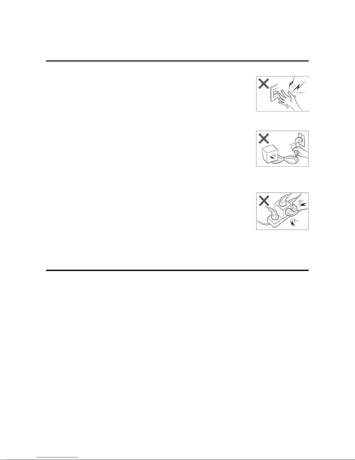
1-3 Precautions related to product safety
O Do not pull the power cord and do not touch the power plug or aux power switch
with wet hands.
– It might cause electric shock or fire.
O A damaged power line or power plug must be replaced to prevent danger.
O Do not bend the power cable with excessive force, and do not place a heavy weight
on the case as it might damage the cable.
– It might cause electric shock or fire.
O Do not use multiple electric outlets.
– This might cause electric shock or fire.
O Connect the ground terminal when necessary.
– Y ou must connect the ground terminal if you determine that there is a danger of electric
leakage due to moisture or water.
O Unplug the power cable or turn off the auxiliary power switch for electric part
replacement and repair service.
– Otherwise it might cause electric shock.
O Instruct end users to separate the batteries from the remote controllers and store
them separately when the product is not used for long time.
– Otherwise leakage from the dry cell may cause problems with the remote controller.
1-4 Other precautions
O The pipes should have no leaks during installation, and the compressor must be stopped before removing connecting
pipes for pump down work. Operating the compressor while the service valve is open and coolant pipe is not properly
connected may cause explosion or injury due to abnormal high pressure created inside the coolant cycle as the air can be
absorbed through the pipe.
O Pump Down work procedure (When uninstalling the product)
– Turn on the air conditioner, select cooling operation, and run the compressor for more than three minutes.
– Release the high pressure and low pressure valve caps.
– Close the high pressure valve completely using an L-wrench
– After about two minutes, close the low pressure valve completely.
– Stop running the air conditioner.
– Separate the connecting pipe.

2-1
□ 360 Cassette
□ Differentiated innovation air cooling
It delivers a cool air evenly with the circular air current and provides a wide and agreeable cooling area than general ceiling
air conditioners.
□ Refreshing and soft wind
It provides a horizontal air current that form natural convection instead of unpleasant direct wind.
It is consumer-friendly product that prevents the sudden effective temperature tumble.
□ High quality circular design
It applied the wind direction control technology (Coanda effect) which uses the booster fan. Epoch-making circular design
that eliminates the blade.
□ Eco-friendly air conditioner
It is eco-friendly air conditioner that is certified a RoHS technology as well as realize high effectiveness, low noise, super
power saving.
□ Electricity savings through S- Inverter System
Apply S-inverter system that change capacity to 10~160% according to circumstance by one compressor and reduce
optimum cooling effect and unnecessary electricity consumption.
□ Clearness function of four seasons high efficiency
Energy consumption and driving noise decrease more because can operate clearness function separately.
Make healthy and clean environment by bacillus exclusion function and active oxygen neutralization function that virus
doctor at air conditioner driving removes air various hazardous substances operating always..
2.
Product Specifications
2-1 The Feature of Product
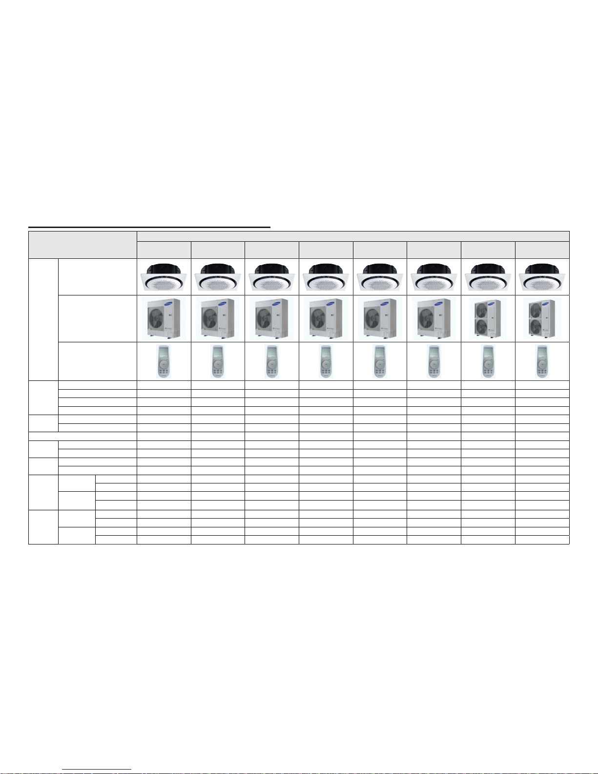
2-2 2-3
ITEM
Development Model
AC090M N4PKH
AC090MXADKH
AC100MN4P KH
AC100MXA DKH
AC100MN4P KH
AC100MXA DKH
AC120MN4PK H
AC120MXAD KH
AC120MN4PK H
AC120MXAD KH
AC120MN4PK H
AC120MXAD NH
AC071MN4PK H
AC140MN4PK H
AC140MXAD KH
AC140MN4PK H
AC140MXAD NH
Design
Indoor Unit
Outdoor Unit
Remote Controller
Capacity
Cooling[w] 9 10 10 12 12 12 13.4 13.4
Heat ing [ W] 10 11.2 11.2 13 13 13 15.5 15. 5
Power input
Cooling[w] 2820 3400 3400 4700 4700 4700 4450 4450
Heating [W] 2650 3150 3150 4000 4000 4000 4540 4540
EER/COP
Cooling[w] 6.8 6.8 6. 8 5.7 5.7 5.7 3.01 3.01
Heating [W] 4.3 4.3 4.3 4.1 4.1 4.1 3.41 3.41
Voltage / Frequency
1Φ, 220-240V~/50Hz 1Φ, 220-240V~/50Hz 1Φ, 220-240V~/50Hz 1Φ, 220-240V~/50Hz 1Φ, 220-240V~/50Hz 3Φ, 380-415V 3N~/50Hz 1Φ, 220-240V~/50Hz 3Φ, 380-415V 3N~/50Hz
Running
Current
Coo li ng [w] 12.7 15.1 15.1 20. 5 20 .5 7.1 20 7
Heating [W] 12.5 14.6 14.6 17.5 17.5 6.3 19.5 7
Noise
Indoor Unit [dBA] (C/H)
48/48 50/50 50/50 50/50 50/50 50/50 51/51 51/51
Outdoo r Unit [dBA] (C /H) 57/59 58/60 58/60 59/61 59/61 59/61 60/62 60/62
Size (W*H*D)
Net Dimension
(WxHxD)
Indoor Unit [mm]
947*947*365 947*947*365 947*947*365 947*947*365 947*947*365 947*947*365 947*947*365 947*947*365
Outdoor Unit [mm]
990*990*414 990*990*414 990*990*414 990*990*414 990*990*414 990*990*414 990*990*414 990*990*414
Shipping
Dimension
(WxHxD)
Indoor Unit [mm]
940*330*998 940*330*998 940*330*998 940*330*998 940*330*998 940*330*998 940*330*1210 940*330*1210
Outdoor Unit [mm] 995*426*1096 995*426*1096 995*426*1096 995*426*1096 995*426*1096 995*426*1096 995*426*1388 995*426*1388
Weight (kg)
Net
Indoo r Unit [kg ] 24 24 24 24 24 24 26 26
Outdoor Unit [kg] 28.5 28.5 28.5 28.5 28.5 28.5 30.5 30.5
Shipping
Indoor Unit [kg] 72 72 72 80 8 0 80 85 85
Outdoor Unit [kg] 77 77 77 85 85 85 94 94
2-2 Product Specifications
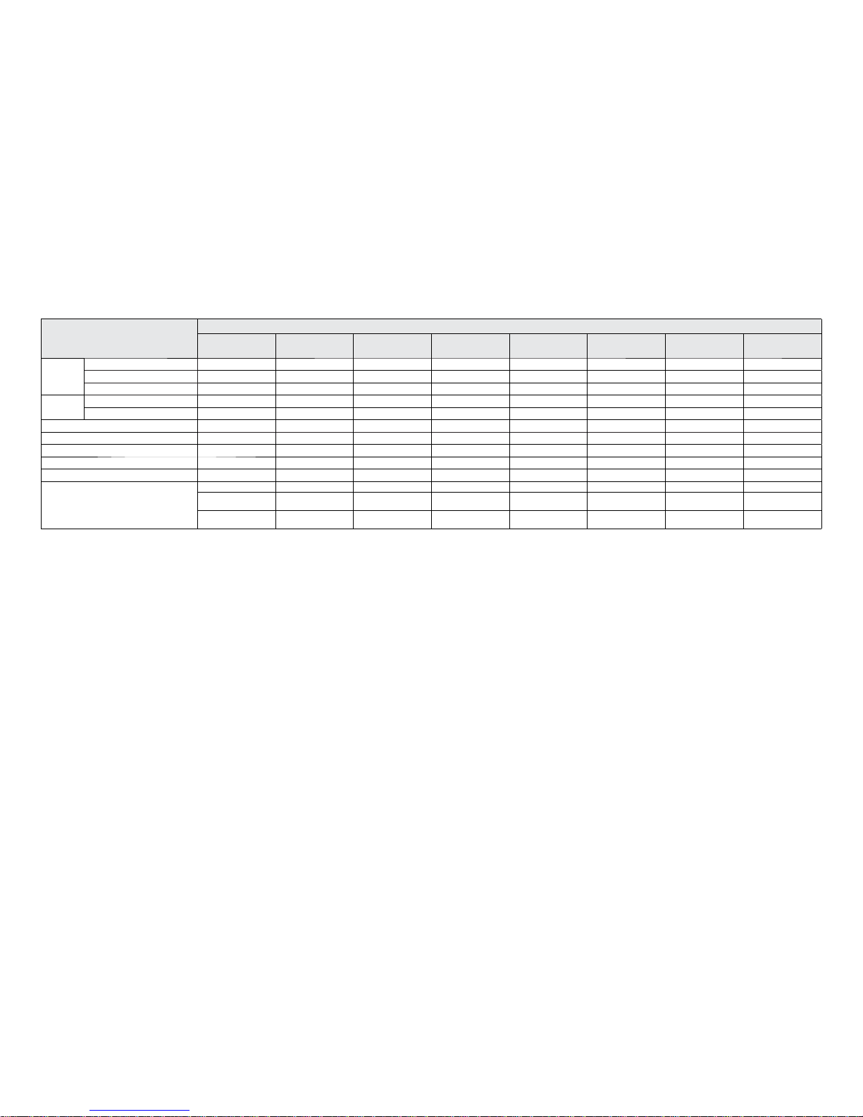
2-4 2-5
ITEM
Development Model
AC090M N4PKH
AC090MXADKH
AC100MN4P KH
AC100MXA DKH
AC100MN4P KH
AC100MXA DKH
AC120MN4PK H
AC120MXAD KH
AC120MN4PK H
AC120MXAD KH
AC120MN4PK H
AC120MXAD NH
AC071MN4PK H
AC140MN4PK H
AC140MXAD KH
AC140MN4PK H
AC140MXAD NH
Harness spec
Indoor fan motor
DB31-00577D DB31-00577D DB31-00577D DB31-00577D DB31-00577D DB31-00577D DB31-00577D DB31-00577D
Compressor UG8T300FUBJUSG UG8T300FUBJUSG UG8T 300FUBJUSG UG5TK1450FJX UG5TK1450 FJX U G5T K1450FJX UG5TK1450 FJX U G5T K1450FJX
Outdoor fan motor
DB31-00579B DB31-00579B DB31-00579B DB31-00579B DB31-00579B D B31-00579B DB31-00658A DB31-00658A
Designed
pressure
High presssure 4.1 Mpa 4.1 Mpa 4.1 Mpa 4.1 Mpa 4.1 Mpa 4.1 Mpa 4.1 Mpa 4.1 Mpa
Low pressure 1.4 Mpa 1.4 Mpa 1.4 Mpa 1.4 Mpa 1.4 Mpa 1.4 Mpa 1.4 Mpa 1.4 Mpa
Refrigerant / Factory charging
3000 3000 3000 3000 3000 3000 3400 3400
Additional refrigerant 50g/m 50g/m 50g/m 50g/m 50g/m 50g/m 50g/m 50g/m
Basic piping length
55555555
Max. piping leng th 50 50 50 50 50 50 75 75
Max. level different 3030303030303030
Option code
01007F-19547C-275A64-370040 01007F-19548C-276470-370040 01007F-19548C-276470-370040 01007F-19549D-277882-370040 01007F-19549D-277882-370040 01007F-19549D-277882-370040 01107F-1954AF-278CA0-370040 01107F-1954AF-278CA0-370040
020000-100000200000-300000
020000-100000200000-300000
020000-100000200000-300000
020000-100000-
200000-300000
020000-100000200000-300000
020000-100000200000-300000
020000-100000200000-300000
020000-100000200000-300000
030000-100000200000-300000
030000-100000200000-300000
030000-100000-
200000-300000
030000-100000-
200000-300000
030000-100000200000-300000
030000-100000200000-300000
030000-100000200000-300000
030000-100000200000-300000
2-6
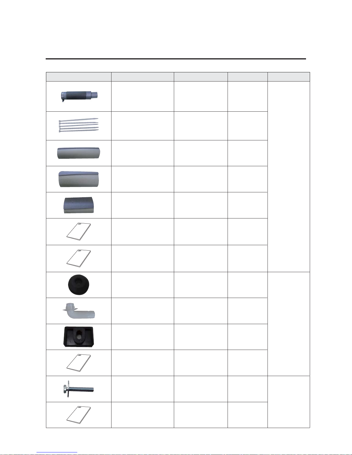
2-3 Specifications of optional items
2-3-1 Accessories
Item Description Code No. Q’ty Remark
ASSY DRAIN- HOSE
DB94-02719B
1
Standard / Indoor unit
Cable tie
DB65-00191A
6
Seal-drain ass'y
DB62-05810A
1
Seal-drain ass'y
DB94-05810F
1
Seal-drain ass'y
DB94-05810G
1
Indoor unit installation manual
DB68-05899A
1
USER MANUAL
DB68-05918A
1
Drain cap
DB63-10355C
3
(AC071KX4DKH : 4)
Standard / Outdoor
unit
Pipe plug
DB67-00806A
1
Rubber Leg
DB73-20134A
(AC071KX4DKH :
DB73-00179A)
4
Outdoor unit installation manual
DB68-05565A
1
Bolt-flange
6009-001435
4
Standard / Panel
INSTALL MANUAL
DB68-05903A
1
Product Specifications
2-7
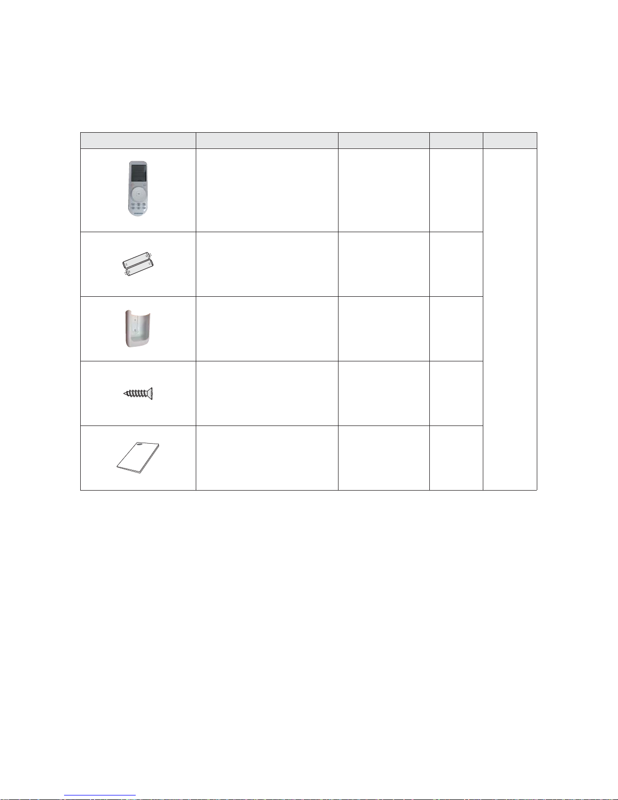
Item Description Code No. Q’ty Remark
Wireless remote controller
DB93-15771C
1
Optional
Batteries for remote controller
(specification: "AAA" type)
4301-000121
2
Remote controller holder
DB61-06607A
1
M4×16 Screw
6002-000581
2
User’s manual
DB68-05911A
1
2-3-2 Wireless remote controller (AR-KH00E)
Product Specifications
2-8
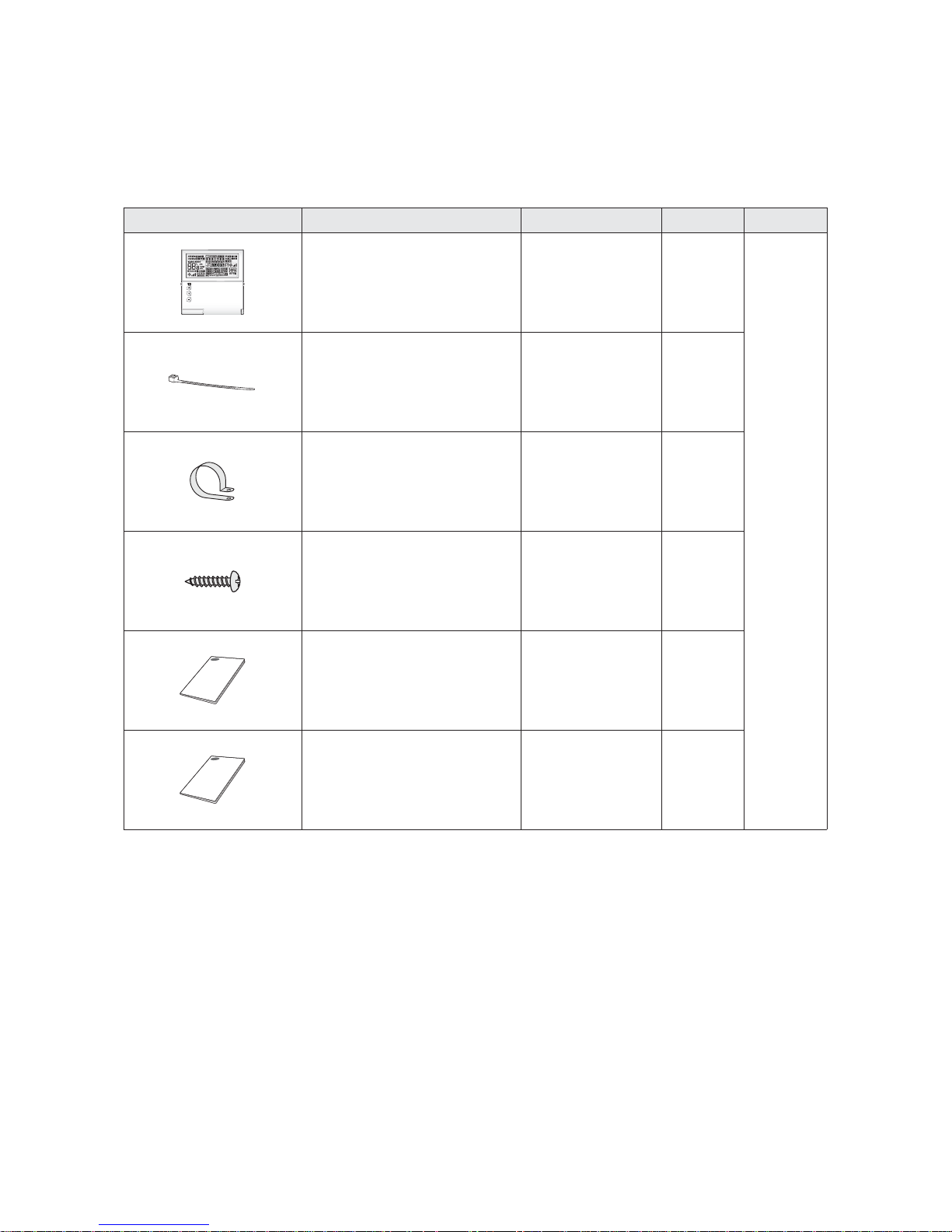
2-3-3 Wired remote controller (MWR-WE10N)
Item Description Code No. Q’ty Remark
Wired remote controller DB93-11251F 1
Optional
Cable tie DB65-10088B
2
Cable clamp DB65-10074E 3
M4×16 Screw 6002-000474 5
User's manual DB68-03732A 1
Installation manual DB68-03716A 1
Product Specifications
2-9
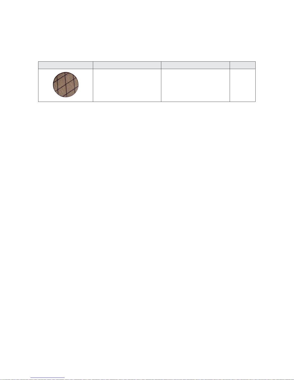
2-3-4 Filter specifications
Item Description Code No. Remark
FILTER-AIR DB63-03764A
3-1
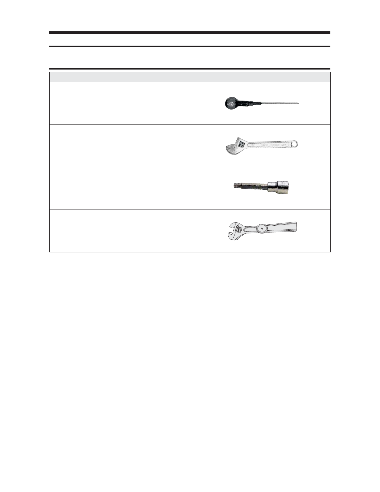
Item Remark
+ Screw Driver
Monkey Spanner
(8mm, 10mm, 13mm)
M6, M8 Hex Wrench
Spanner Torque Wrench
3. Disassembly and Reassembly
3-1 Necessary Tools
3-2
3-2 Indoor Unit
No. Parts Procedure Remark
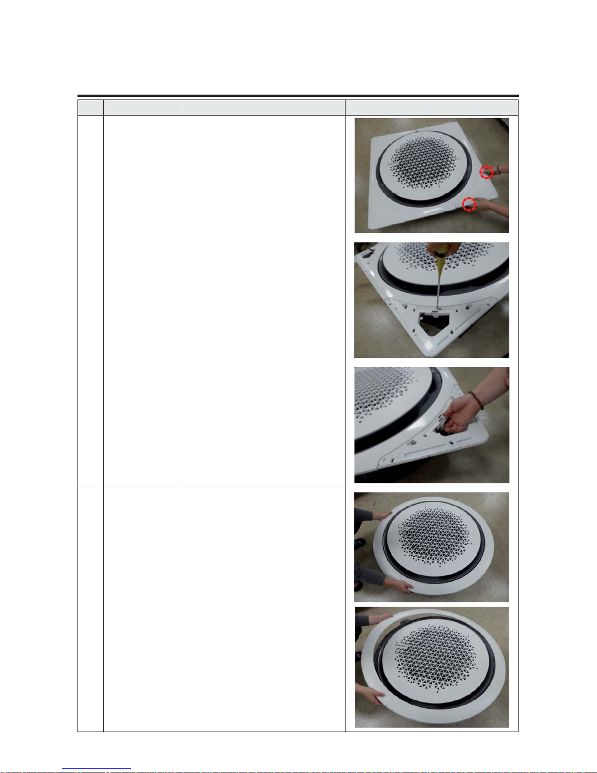
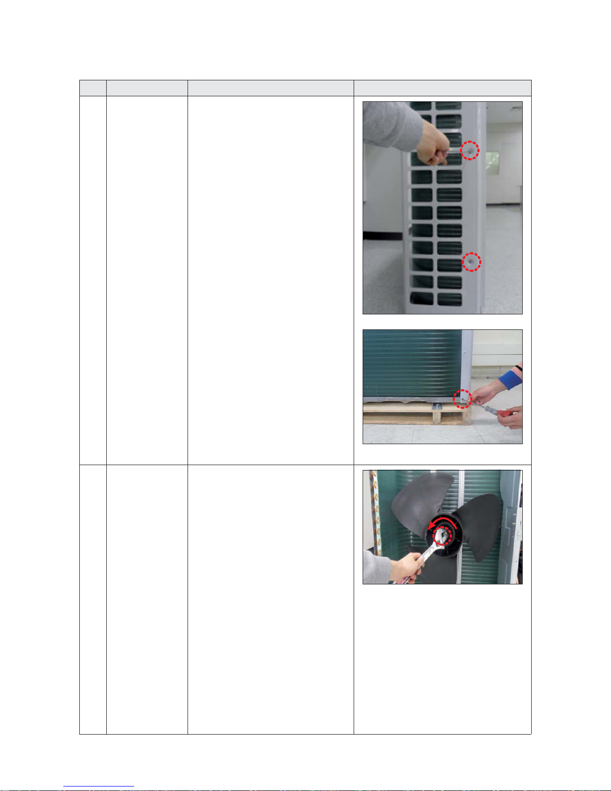
1 Panel
▶ Ceiling type Panel
1) Pull up the corner 4 places of Panel and
separate it.
2) Remove the 4 screws from the corner of
Panel. (Use +Screw Driver)
3) Pull the hook of Panel and then separate the
Panel from the Indoor Unit.
1 Panel
▶ Open type Panel
1) Rotate the outside Panel to counterclockwise
direction and then separate it.
Disassembly and Reassembly
3-3
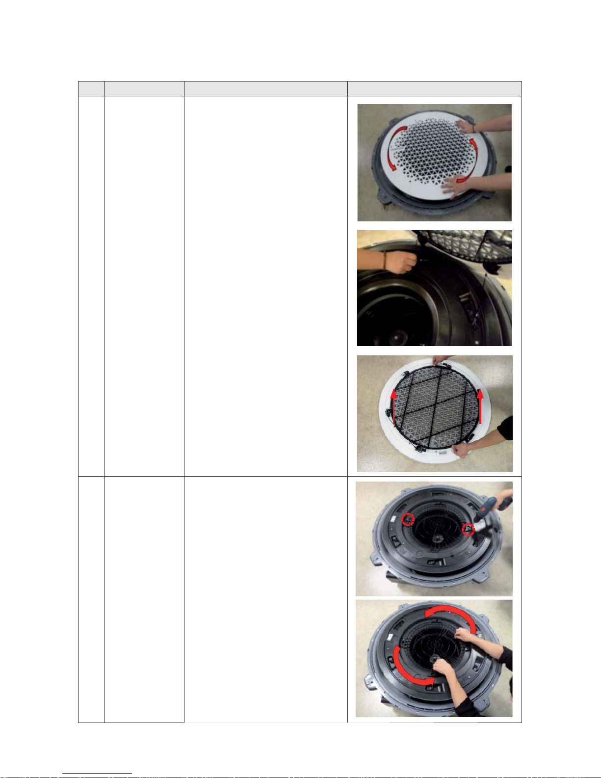
No. Parts Procedure Remark
1 Panel 2) Rotate the Grille to counterclockwise
direction.
3) Remove the safety clip of Grill inside and then
separate the Panel from the Indoor Unit.
4) Pull up the Filter from the Grill and separate it.
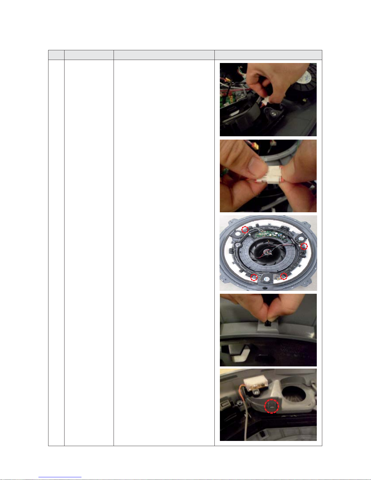
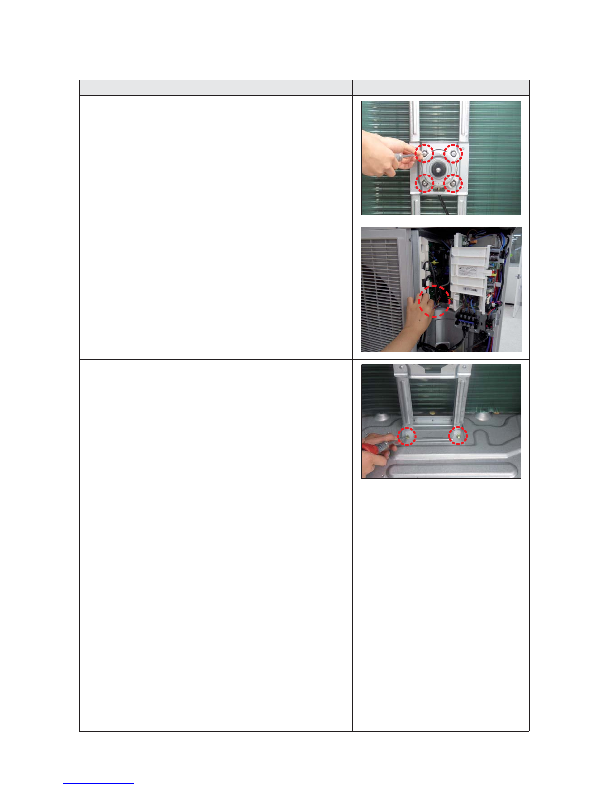
2
Control Box
1) Reomove the 2 screws which is fixed to the
Indoor Unit upper part.(Use +Screw Driver)
2) Rotate the Guard Fan to counterclockwise
direction and separate it
Disassembly and Reassembly
3-4
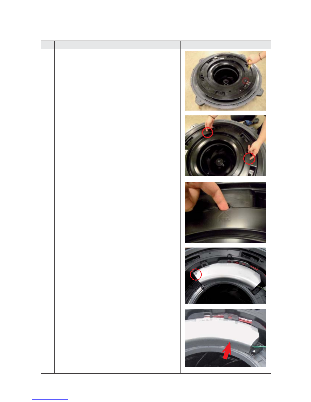
No. Parts Procedure Remark
2
Control Box
3) Reomove the 1 screw which is fixed to the
Indoor Unit upper part.(Use +Screw Driver)
4) Put finger in the "PULL" marked groove and
then pull up the Cover
5) Put finger in the "PULL" marked groove and
then avoids the hook and it opens the Control
Box Cover
Disassembly and Reassembly
3-5
No. Parts Procedure Remark
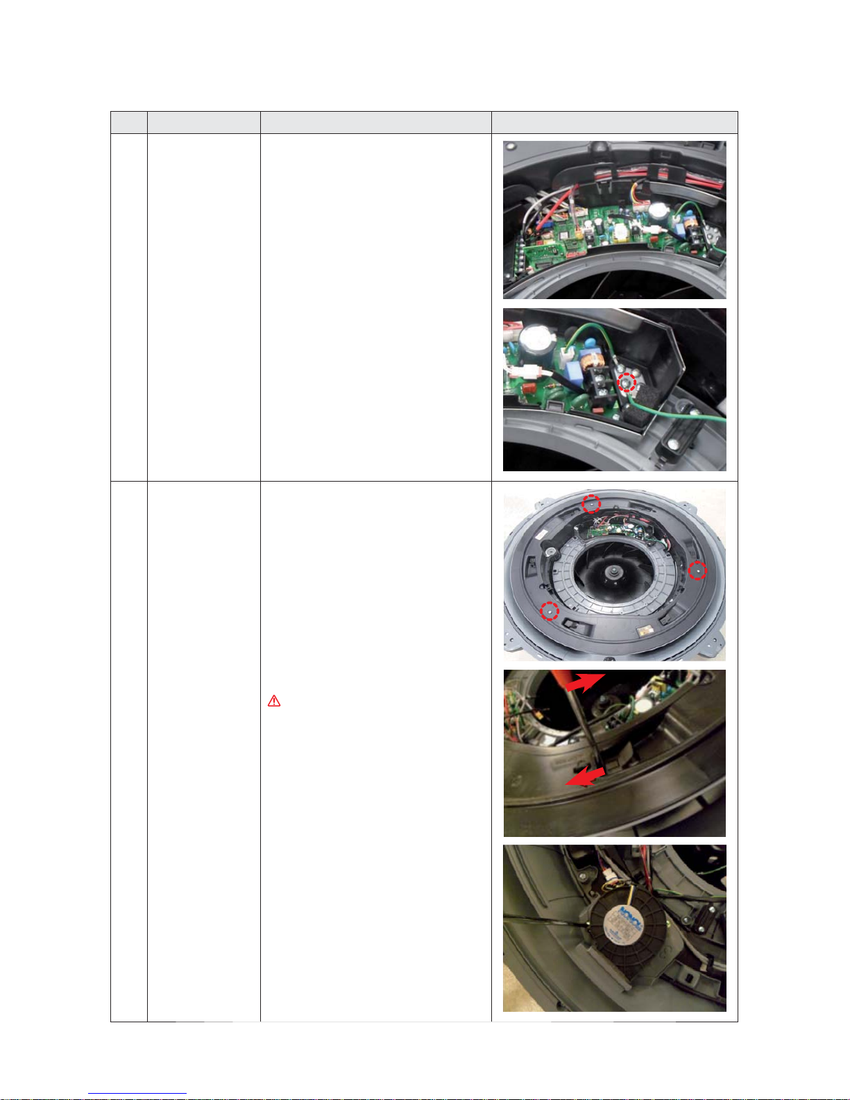
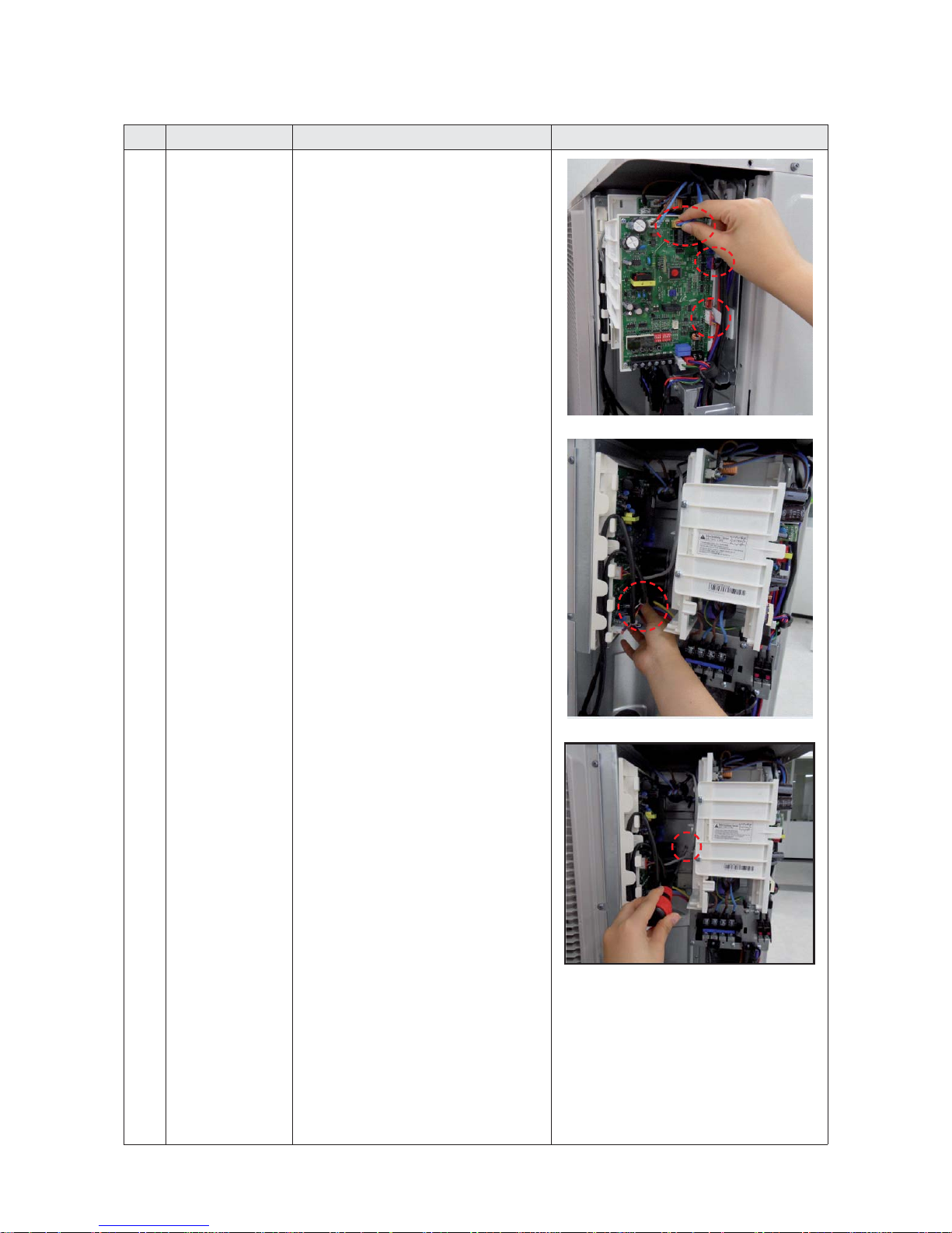
2
Control Box
6) Separate the connectors from the Control Box.
7) Remove the ground screw.
(Use +Screw Driver)
3
Top Cover & Drain Pan
1) Remove the 3 screws. (Use +Screw Driver)
2) Push the hook and separate the Cover.
Damage can occur to product in case of use a
sharp tool.
3) Remove the screw which is fixed to Booster
Fan. (Use +Screw Driver)
Disassembly and Reassembly
3-6
No. Parts Procedure Remark
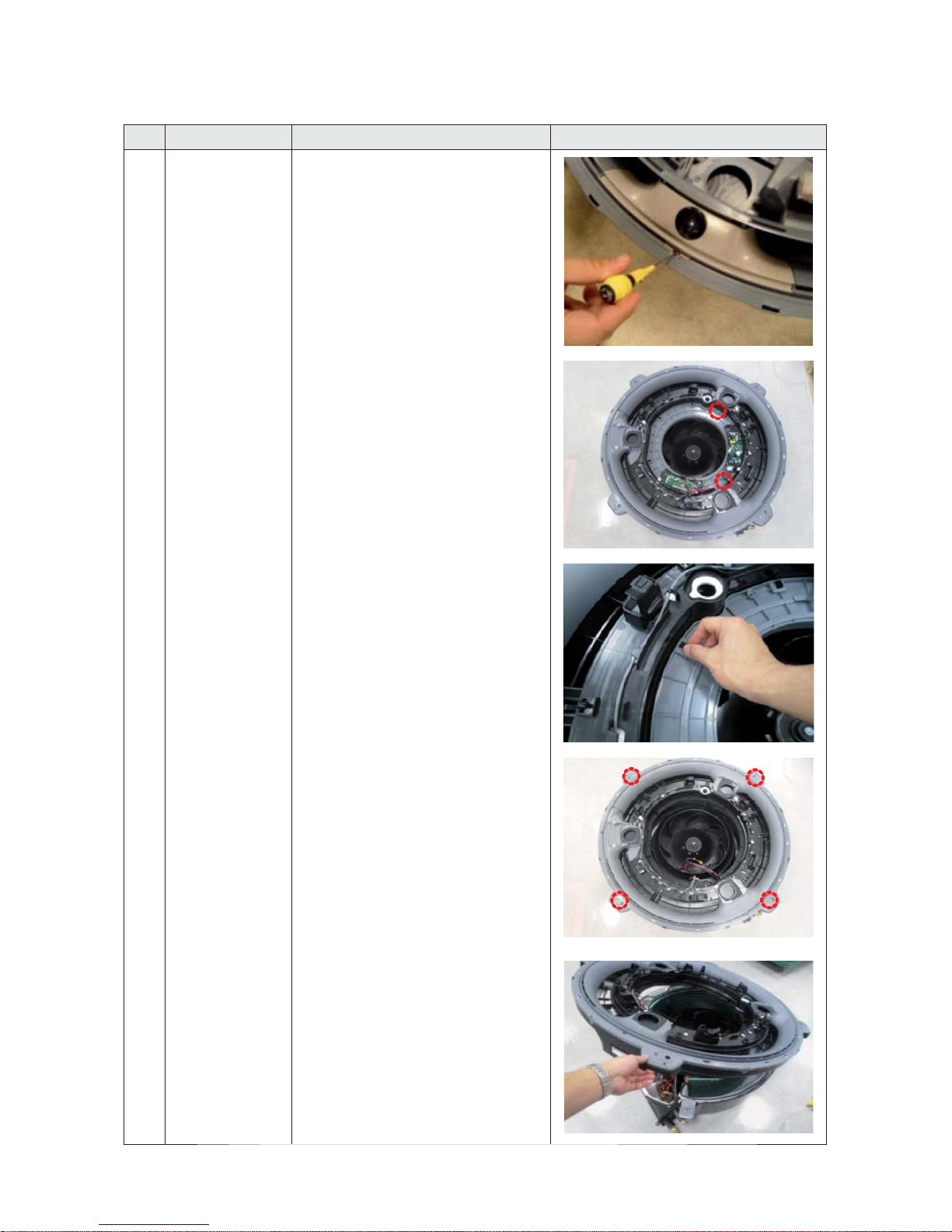
3
Top Cover & Drain Pan
4) Pull the Booster Fan connector and separate
the connector.
5) Remove the 4 screws. (Use +Screw Driver)
6) Push the hook and separate the Cover.
Disassembly and Reassembly
3-7
No. Parts Procedure Remark
3
Top Cover & Drain Pan
7) Remove the screw and separate the Display
Cover. (Use +Screw Driver)
8) ) Remove the 2 screws. (Use +Screw Driver)
9) Push the hook and separate the Cover.
10) Remove the 8 screws. (Use +Screw Driver)
11) Separate the Indoor Unit upper part from
the Body
Disassembly and Reassembly
3-8
No. Parts Procedure
Remark
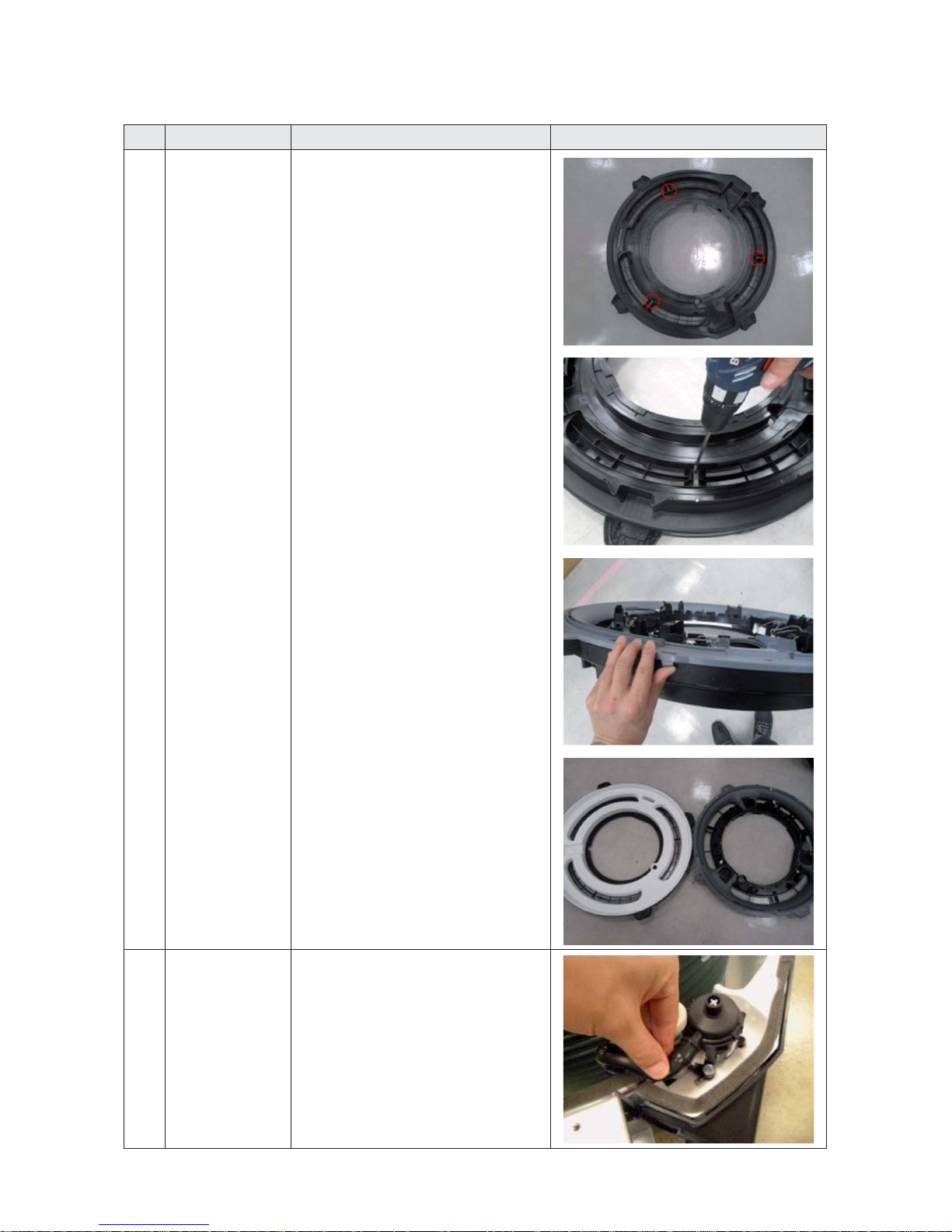
3
Top Cover & Drain Pan
12) Remove the 3 screws. (Use +Screw Driver)
13) Pull the hook that is on the side and separate
the Cover.
4
Drain Pump & Hose
1) Separate the Drain Hose from the Drain Pump.
Disassembly and Reassembly
3-9
No. Parts Procedure
Remark
4
Drain Pump & Hose
2) Remove the 2 screws and separate the Drain
Hose that is on the side lower part of Indoor
Unit (Use +Screw Driver)
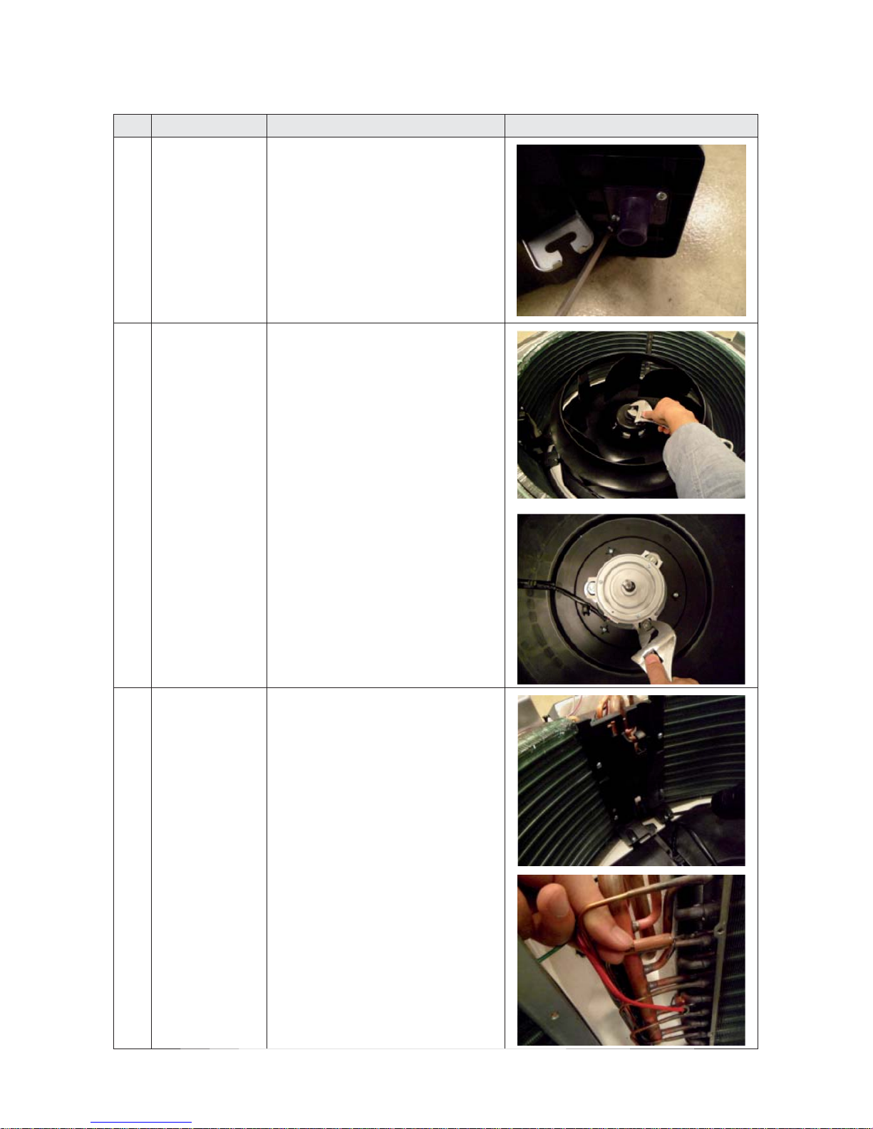
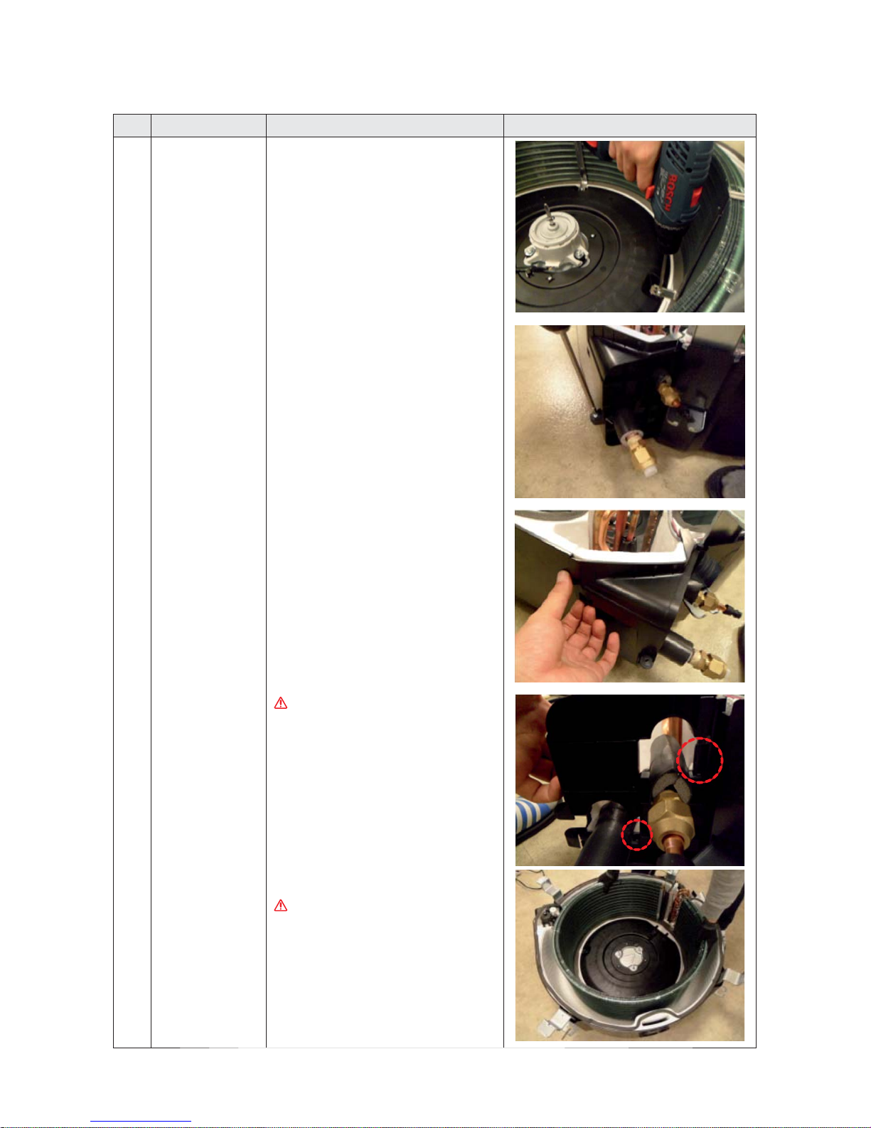
5
Fan & Motor
1) Remove the hex nut which is fixed to top of
Fan and separate the Fan from the Motor.
(Use Monkey Spanner)
2) Remove the 3 hex nuts which is fixed to Motor
and separate the Motor from the Indoor Unit.
(Use Monkey Spanner)
6
Temperature Sensor
1) Remove the 6 screws which is fixed to
Evaporator and separate the Partition.
2) Separates the Temperature Sensor which is
fixed to Evaporator Pipe with the fixing clip
together by the hand.
Disassembly and Reassembly
3-10
No. Parts Procedure
Remark
4
Evaporator
1) Remove the screws which is fixed to Indoor
Unit and separate the Evaporator fixing
bracket. (Use +Screw Driver)
2) Remove screws which is fixed to Indoor Unit
and pull the hook and then separate the Drain
Cover. (Use +Screw Driver)
When assemble, be careful with the
interference structure of piping
projecting part.
3) Separate the Evaporator from the Indoor Unit.
If you remove the Evaporator withbare hands,
it may injure your hands, gloves must be worn.
Disassembly and Reassembly
3-11
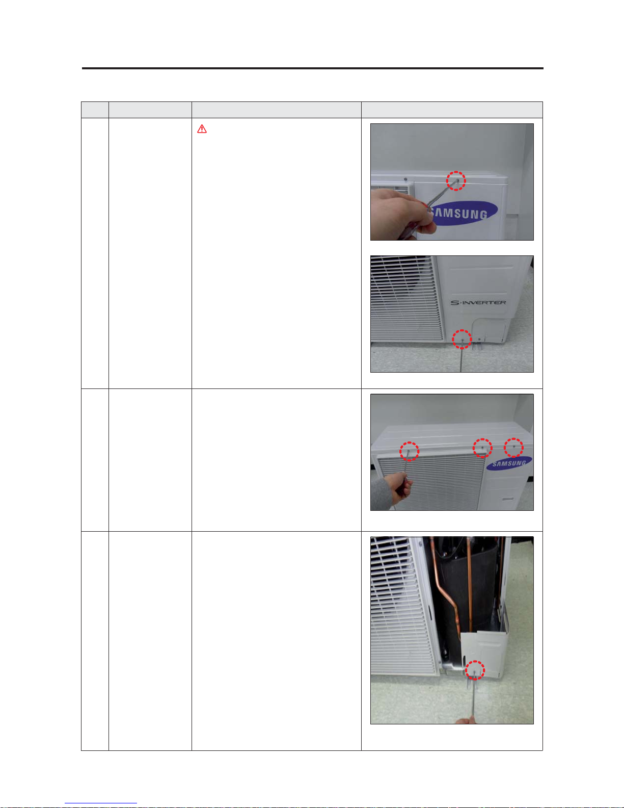
No. Parts Procedure Remark
1
Cabinet Front RH
Turn off the power before disassembly
necessarily.
1) Remove the 2 screws from the Cabinet Front
RH and separate it. (Use +Screw Driver)
2
Cabinet Upper
1) Remove the 9 screws which is fixed to each
side of Cabinet Upper and separate it. (Use
+Screw Driver)
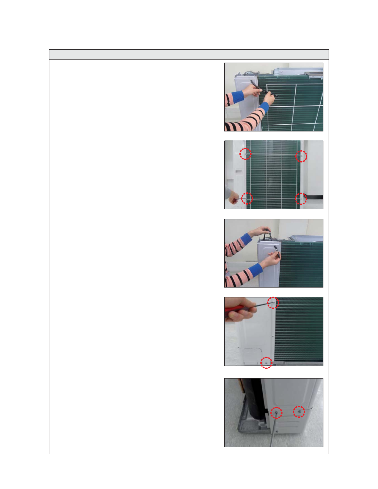
3
Cabinet-Installation
Front Part
1) Remove the 1 screw which is fixed to
Cabinet-Installation Front Part and separate
it. (Use +Screw Driver)
■ AC090/100/120MXAD*H
3-3. Outdoor Unit
Disassembly and Reassembly
3-12
No. Parts Procedure Remark
4
Outdoor Unit Guard
1) Pull out the sensor from the Outdoor Unit
Guard and separate it.
2) Remove the 4 screws which is fixed to
Outdoor Unit Guard and separate it. (Use +
Screw Driver)
5
Cabinet Rear RH
1) Pull out the sensor from the Cabinet Rear RH
and separate it.
2) Remove the 4 screws which is fixed to each
side of Cabinet Rear RH and separate it. (Use +
Screw Driver)
Disassembly and Reassembly
3-13
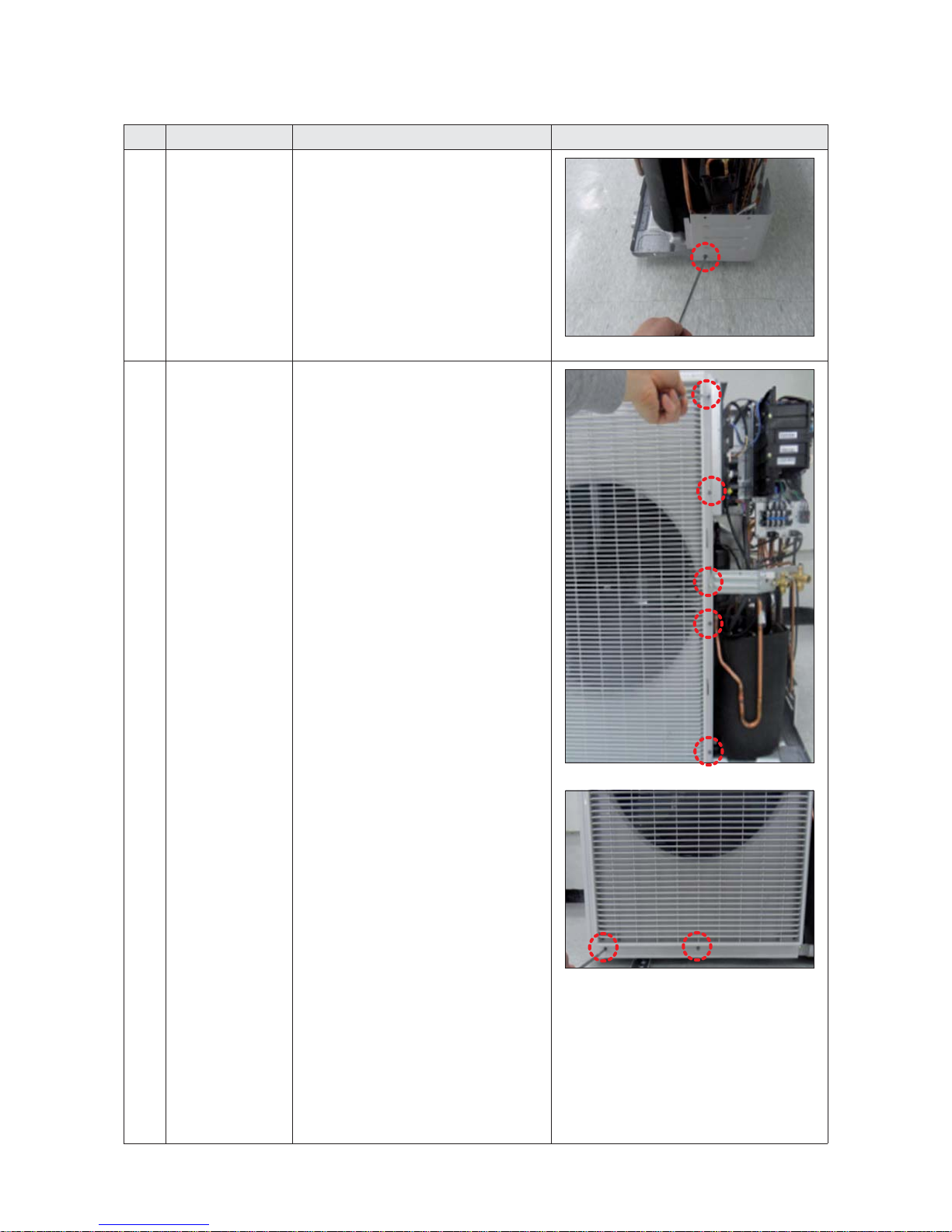
No. Parts Procedure Remark
6
Cabinet-Installation
Rear Part
1) Remove the 1 screw from the Cabinet-
Installation Rear Part and separate it.(Use +
Screw Driver)
7
Cabinet Front LF
1) Remove the 10 screws from the Cabinet
Front LF and separate it. (Use +Screw Driver)
Disassembly and Reassembly
3-14
No. Parts Procedure Remark
7
Cabinet Front LF
8
Fan
1) Remove the 2 fixing nuts like the picture
on the right side. (Use Hexagon Wrench,
Monkey Spanner, Hexagon Socket)
Disassembly and Reassembly
3-15
No. Parts Procedure Remark
9 Motor 1) Separate the Fan Propeller.
2) Remove the 8 screws which is fixed to
Motor. (Use +Screw Driver)
3) Separate the Motor Wire connector from the
Outdoor Unit Control Part.
10
Bracket Motor
1) Remove the 2 screws from the Bracket Motor
and separate it. (Use +Screw Driver)
Disassembly and Reassembly
3-16
No. Parts Procedure Remark
11
Control Part
1) Separate the 4 connectors from the Outdoor
Unit Control part.
2) Remove the 1 screw which is fixed to Control
Part. (Use +Screw Driver)
3) Separate the Control Part.
Disassembly and Reassembly
3-17
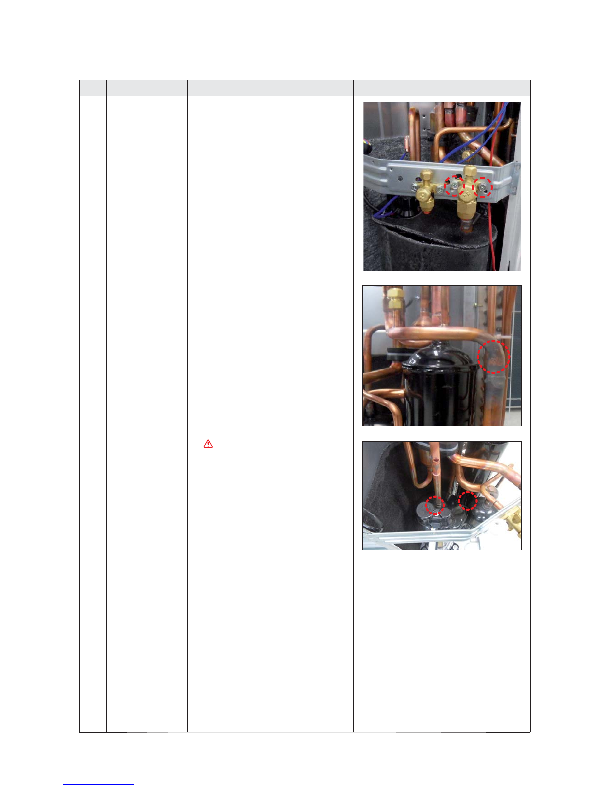
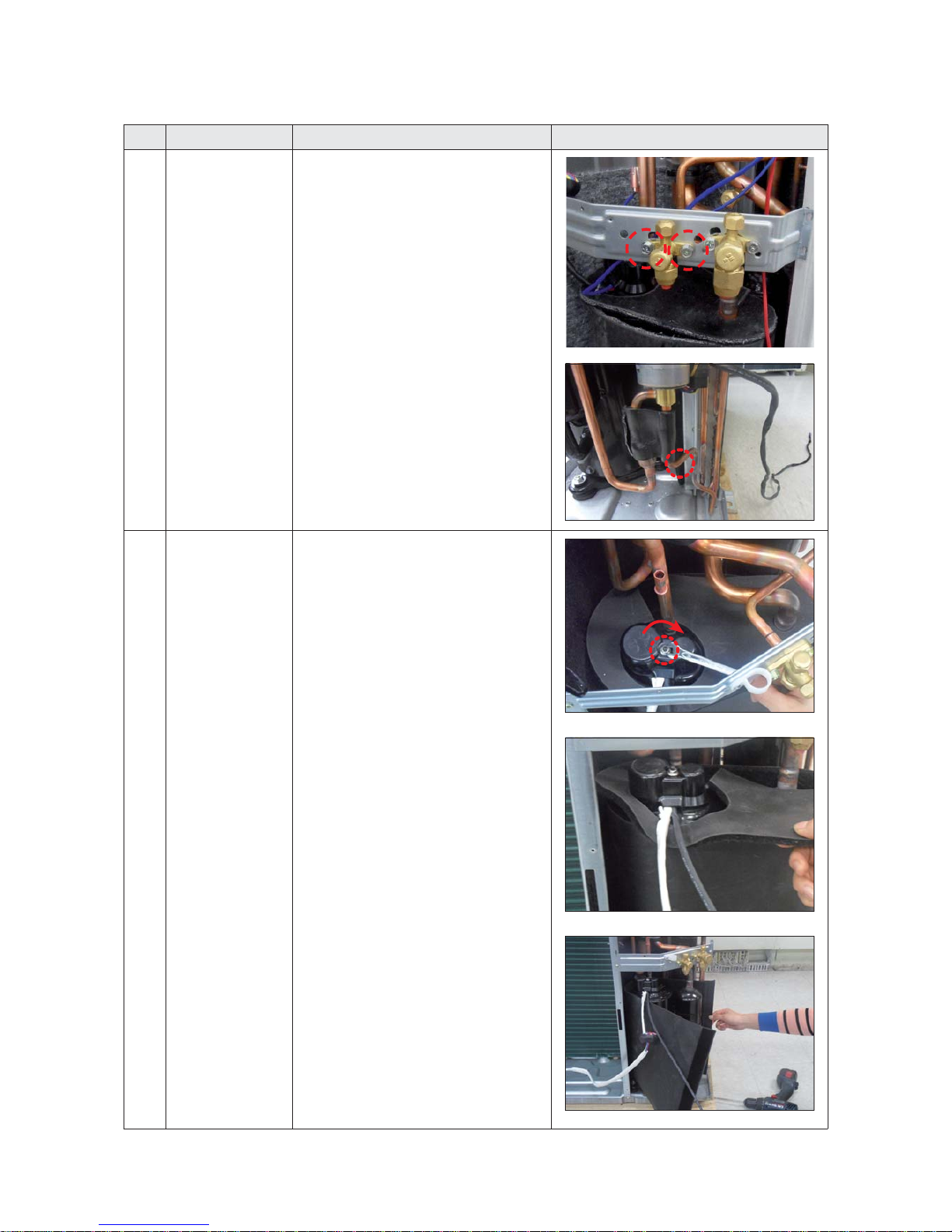
No. Parts Procedure Remark
12
4 Way Valve
1) First, discharge the refrigerant.
2) Remove the 2 screws which is fixed to
Service Valve and separate it. (Use +Screw
Driver)
3) Separate the inlet and outlet pipes by
welding torch.
If you separate the Compressor, Heat
Exchanger or Pipe, please fully discharge
refrigerant in the Compressor and then
separate the Pipe by welding torch.
Disassembly and Reassembly
3-18
No. Parts Procedure Remark
13
EEV Valve
1) Remove the 2 screws which is fixed to
Service Valve and separate it. (Use +Screw
Driver)
2) Separate the inlet and outlet pipes by
welding torch.
14
Compressor
1) Remove the 1 fixing nut from the end of
Cover and separate it. (Use Hexagon Wrench,
Monkey Spanner, Hexagon Socket)
2) Separate the Felt Compressor.
 Loading...