

Samsung AC100KXADEH, AC100KNPDEH, AC140KXADGH, AC140KXPDEH Installation Manual
Air conditgioner
User manual/Installation manual
AR✴✴HVSD✴✴
• Thank you for purchasing this Samsung air conditioner.
• Before operating this unit, please read this user manual carefully and retain it for future
reference.
Air conditioner
Installation manual
AC✴✴✴KNPDEH/AC✴✴✴KXAD✴H
• Thank you for purchasing this Samsung air conditioner.
• Before operating this unit, please read this user manual carefully and retain it for future
reference.

Contents
English
Contents
Safety Information 3
General information
Installing the unit
Power supply line, fuse or circuit breaker
Installation Procedure 6
Step 1 Choosing the installation location
Step 2 Unpacking
Step 3 Checking and preparing accessories
Step 4 Drilling a hole through a wall
Step 5 Taping the pipes, cables, and drain hose
Step 6 Connecting the refrigerant pipes
Step 7 Optional: Cutting and flaring the pipes
Step 8 Connecting the power and communication cables
Step 9 Optional: Extending the power cable
Step 10 Checking the earthing
Step 11 Performing gas leakage test
Step 12 Evacuating the air
Step 13 Charging the refrigerant
Step 14 Fixing and insulating the connection part for refrigerant pipes
Step 15 Installing and connecting the drain hose
Step 16 Performing drainage test
Step 17 Checking the earthing
Step 18 Performing the final check and trial operation
Appendix 25
COMMISSION DELEGATED REGULATION (EU) No 626/2011i)
PRODUCT FICHE (ENERGY LABELLING OF AIR CONDITIONERS)
Troubleshooting
For information on Samsung’s environmental commitments and product specific regulatory obligations e.g. REACH
visit: samsung.com/uk/aboutsamsung/samsungelectronics/corporatecitizenship/data_corner.html
2
ii)

English
Safety Information
Carefully follow the precautions listed as below because
they are essential to guarantee the safety of SAMSUNG
product.
WARNING
∙ Always disconnect the air conditioner from the power
supply before servicing it or accessing its internal
components.
∙ Verify that installation and testing operations are
performed by qualified personnel.
∙ Verify that the air conditioner is not installed in an
easily accessible area.
General information
∙ Carefully read the content of this manual before
installing the air conditioner and store the manual in
a safe place in order to be able to use it as reference
after installation.
∙ For maximum safety, installers should always
carefully read the following warnings.
∙ Store the manual in a safe location and remember to
hand it over to the new owner if the air conditioner is
sold or transferred.
∙ This manual explains how to install an indoor unit
with a split system with two SAMSUNG units. The use
of other types of units with different control systems
may damage the units and invalidate the warranty.
The manufacturer shall not be responsible for
damages arising from the use of non compliant units.
∙ The manufacturer shall not be responsible for
damage originating from unauthorized changes or
the improper connection of electric and hydraulic
lines. Failure to comply with these instructions or
to comply with the requirements set forth in the
“Operating limits” table, included in the manual, shall
immediately invalidate the warranty.
∙ The air conditioner should be used only for the
applications for which it has been designed: the
indoor unit is not suitable to be installed in areas
used for laundry.
∙ Do not use the units if damaged. If problems occur,
switch the unit off and disconnect it from the power
supply.
∙ In order to prevent electric shocks, fires or injuries,
always stop the unit, disable the protection switch
and contact SAMSUNG’s technical support if the unit
produces smoke, if the power cable is hot or damaged
or if the unit is very noisy.
∙ Always remember to inspect the unit, electric
connections, refrigerant tubes and protections
regularly. These operations should be performed by
qualified personnel only.
∙ The unit contains moving parts, which should always
be kept out of the reach of children.
∙ Do not attempt to repair, move, alter or reinstall the
unit. If performed by unauthorized personnel, these
operations may cause electric shocks or fires.
∙ Do not place containers with liquids or other objects
on the unit.
∙ All the materials used for the manufacture and
packaging of the air conditioner are recyclable.
∙ The packing material and exhaust batteries of the
remote control (optional) must be disposed of in
accordance with current laws.
∙ The air conditioner contains a refrigerant that has
to be disposed of as special waste. At the end of its
life cycle, the air conditioner must be disposed of in
authorized centers or returned to the retailer so that
it can be disposed of correctly and safely.
∙ This product has been determined to be in compliance
with the Low Voltage Directive (2006/95/EC), and the
Electromagnetic Compatibility Directive (2004/108/
EC) and the Machinery Directive (2006/42/EC) of the
European Union.
∙ This appliance is not intended for use by persons
(including children) with reduced physical, sensory
or mental capabilities, or lack of experience and
knowledge, without supervision or instruction
concerning use of the appliance by a person
responsible for their safety. Children should be
supervised to ensure that they do not play with the
appliance.
∙ For use in Europe: This appliance can be used by
children aged from 8 years and above and persons
with reduced physical, sensory or mental capabilities
or lack of experience and knowledge if they have
been given supervision or instruction concerning use
of the appliance in a safe way and understand the
hazards involved. Children shall not play with the
appliance. Cleaning and user maintenance shall not be
made by children without supervision.
Safety Information
3

Safety Information
English
Safety Information
Installing the unit
IMPORTANT: When installing the unit, always remember
to connect first the refrigerant tubes, then the electrical
lines. Always disassemble the electric lines before the
refrigerant tubes.
∙ Upon receipt, inspect the product to verify that
it has not been damaged during transport. If the
product appears damaged, DO NOT INSTALL it and
immediately report the damage to the carrier or
retailer (if the installer or the authorized technician
has collected the material from the retailer).
∙ After completing the installation, always carry out a
functional test and provide the instructions on how to
operate the air conditioner to the user.
∙ Do not use the air conditioner in environments with
hazardous substances or close to equipment that
release free flames to avoid the occurrence of fires,
explosions or injuries.
∙ Our units must be installed in compliance with
the spaces indicated in the manual to ensure
either accessibility from both sides or ability to
perform routine maintenance and repairs. The units’
components must be accessible and that can be
disassembled in conditions of complete safety either
for people or things. For this reason, where it is
not observed as indicated into the manual, the cost
necessary to reach and repair the unit (in safety, as
required by current regulations in force) with slings,
trucks, scaffolding or any other means of elevation
won’t be considered in-warranty and charged to end
user.
Power supply line, fuse or circuit
breaker
∙ For this reason, when provisions of the installation
manual are not complied with, the cost required to
access and repair the units (in SAFETY CONDITIONS,
as set out in prevailing regulations) with harnesses,
ladders, scaffolding or any other elevation system
will NOT be considered part of the warranty and will
be charged to the end customer.
∙ Always make sure that the power supply is compliant
with current safety standards. Always install the air
conditioner in compliance with current local safety
standards.
∙ Always verify that a suitable grounding connection is
available.
∙ Verify that the voltage and frequency of the power
supply comply with the specifications and that the
installed power is sufficient to ensure the operation
of any other domestic appliance connected to the
same electric lines.
∙ Always verify that the cut-off and protection switches
are suitably dimensioned.
∙ Verify that the air conditioner is connected to the
power supply in accordance with the instructions
provided in the wiring diagram included in the
manual.
∙ Always verify that electric connections (cable entry,
section of leads, protections…) are compliant with
the electric specifications and with the instructions
provided in the wiring scheme. Always verify that all
connections comply with the standards applicable to
the installation of air conditioners.
CAUTION
∙ Make sure that you earth the cables.
– Do not connect the earth wire to the gas pipe,
water pipe, lighting rod or telephone wire. If
earthing is not complete, electric shock or fire may
occur.
∙ Install the circuit breaker.
– If the circuit breaker is not installed, electric shock
or fire may occur.
∙ Make sure that the condensed water dripping from
the drain hose runs out properly and safely.
∙ Install the power cable and communication cable of
the indoor and outdoor unit at least 1m away from
the electric appliance.
∙ Install the indoor unit away from lighting apparatus
using the ballast.
– If you use the wireless remote control, reception
error may occur due to the ballast of the lighting
apparatus.
4

English
∙ Do not install the air conditioner in following places.
– Place where there is mineral oil or arsenic acid.
Resin parts flame and the accessories may drop or
water may leak. The capacity of the heat exchanger
may reduce or the air conditioner may be out of
order.
– The place where corrosive gas such as sulfurous
acid gas generates from the vent pipe or air outlet.
The copper pipe or connection pipe may corrode
and refrigerant may leak.
– The place where there is a machine that generates
electromagnetic waves. The air conditioner may not
operate normally due to control system.
– The place where there is a danger of existing
combustible gas, carbon fiber or flammable dust.
The place where thinner or gasoline is handled. Gas
may leak and it may cause fire.
∙ Be sure not to perform power cable modification,
midway wiring, and multiple wire connection.
– It may cause electric shock or fire due to poor
connection or insulation and current limit override.
– When midway wiring is required due to power line
damage, refer to "Step 9 Optional: Extending the
power cable" in the installation manual.
Safety Information
5
English
Installation Procedure
Strong wind
Rooftop
Outdoor UnitOutdoor Unit
Sea Sea
Sea breeze Sea breeze
Outdoor Unit
Protection wall
Sea
Sea breeze
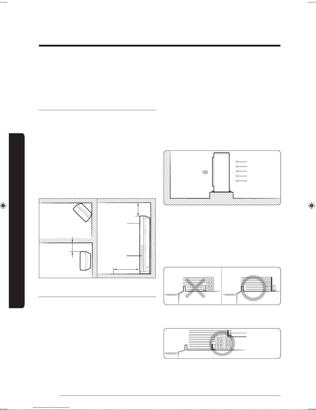
Step 1 Choosing the installation
location
∙ Install the unit where the pipes and cables can be
easily connected to the indoor unit.
∙ Maintain sufficient space for repairs and service.
Determine the installation location considering the
following conditions and obtain the user approval.
Indoor unit
∙ Make sure that condensed water dripping from the
drain hose is directed away safely.
∙ If there is any unavoidable reason to install the unit
at such a place, take the following measures:
∙ Install the unit where the pipes and cables can be
easily connected to the outdoor unit.
∙ Install the unit where there are no obstacles against
the wind around the air intake and air outlet.
∙ Install the unit on a flat and stable surface that can
– When installing the unit at a roadside concentrated
with buildings, install it parallel to the road.
– Install the unit so that the air outlet faces the wall
such as rooftop that may be subjected to strong
wind.
hold the unit’s weight. Otherwise, the unit may
generate noise and vibrations.
∙ Do not install the unit near highly frequented doors
and passages.
∙ Do not install the unit in a location exposed to direct
sunlight.
Installation Procedure
Top view Side view
More than 50cm
∙ When installing the outdoor unit near the seashore,
Air outlet
<Corner installation>
More than 60cm
Air intake
More than 100cm
<Wall installation>
make sure that it is not directly exposed to sea
breeze. If you cannot find an adequate place, a
protection wall should be constructed.
– Install the outdoor unit at a place (such as near
a building) where it can be protected from sea
breeze. Failure to do so may cause damage to the
outdoor unit.
Outdoor unit
∙ Install the unit where it will not experience oil
leakages, salt collection, gas exposure, or sulfide gas
risk, and keep it and safe from other dangers.
∙ Install the unit where does not disturb your neighbors
as they may be affected by the noise or airflow
coming from the unit.
∙ Install the unit where no rainwater can collect on or
near it.
∙ Install the unit in a well-ventilated location away
from direct sunlight or strong winds.
6
∙ If you cannot avoid a place near the seashore,
construct a protection wall around the outdoor unit.
English
∙ Construct a protection wall made of solid material
such as concrete to block sea breeze. Make sure that
its height and width are 1.5 times greater than the
size of the outdoor unit. In addition, secure a space
larger than 600 mm between the protection wall and
the outdoor unit for exhausted air to ventilate.
∙ Install the unit at a place where water can drain
smoothly.
∙ If you have any difficulty in finding an installation
location, contact your manufacturer.
∙ Be sure to clean sea water and dust on the heat
exchanger of the outdoor unit and apply a corrosion
inhibitor on it (at least once in a year).
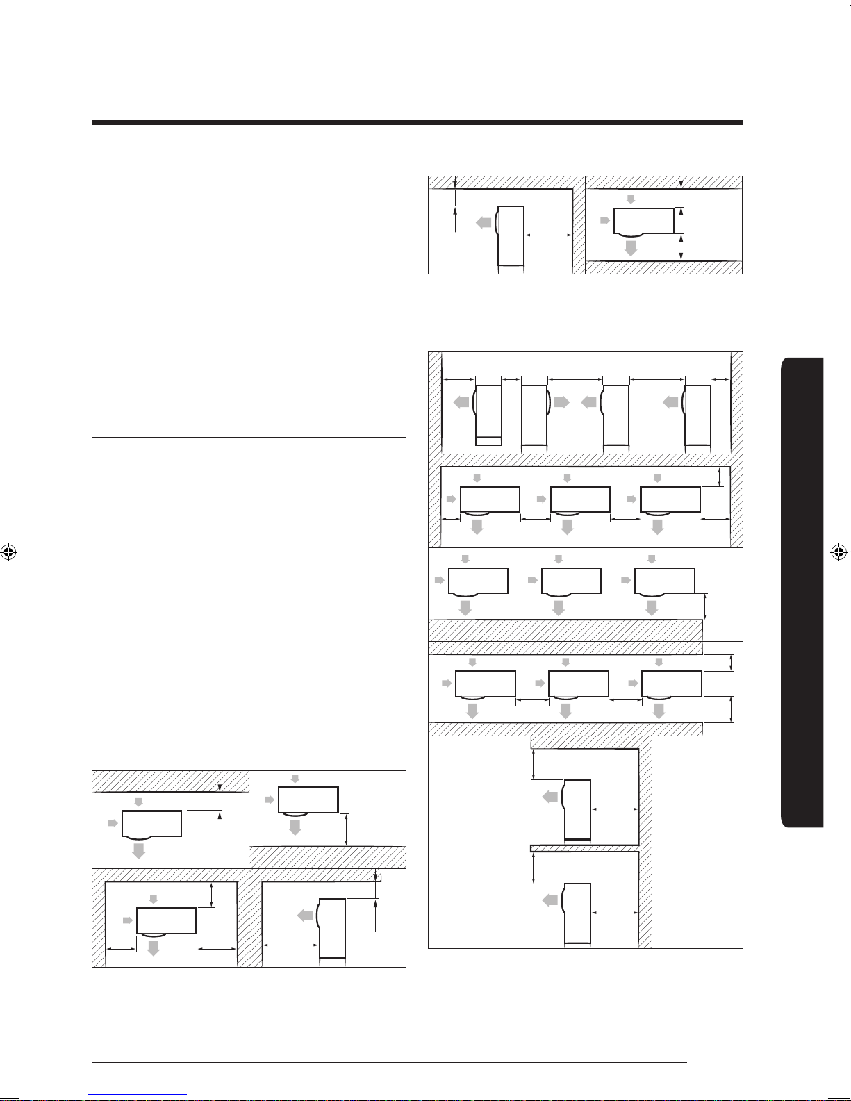
Outdoor unit installation request
∙ The suggested space is based on the outdoor
temperature of 35°C while in operation. If the outdoor
temperature is higher than 35°C, secure more space.
∙ Be sure to secure sufficient clearance for a person
and air flow passage.
∙ See the clearances and dimensions in Minimum
clearances for the outdoor unit (page 7) when
installing the outdoor unit.
∙ If you install multiple outdoor units in the same place,
be sure to secure enough space for ventilation and
free airflow.
∙ If the space for ventilation is insufficient, the air
conditioner may not perform well as designed.
600 or more
300 or
more
When installing more than 1 outdoor unit
1500 or
more
300 or
more
600 or
more
600 or
more
3000 or
more
600 or
more
3000 or
more
300 or more
1500 or more
(Unit: mm)
300 or
more
300 or
more
600 or
more
1500 or
more
300 or more
Installation Procedure
Minimum clearances for the outdoor unit
When installing 1 outdoor unit
300 or more
300 or
more
300 or
more
600 or
more
2000 or
more
(Unit: mm)
1500 or
more
1500 or more
600 or
500 or
more
500 or
more
more
600 or
more
300 or
more
300 or
more
1500 or more
7
Installation Procedure
English
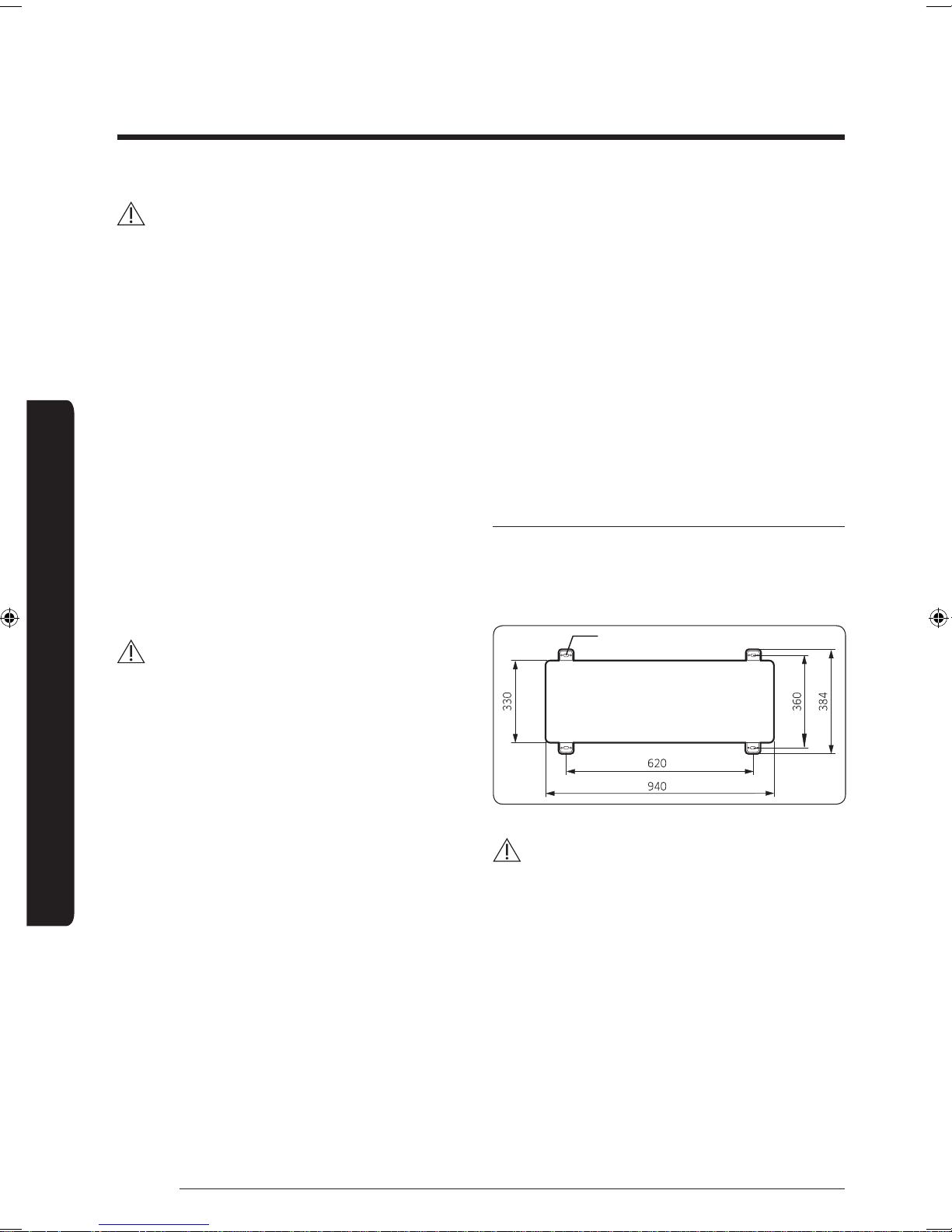
Anchor bolt hole
WARNING
∙ After installing the outdoor unit, apply rust inhibitor
on the internal pipes and heat exchanger.
– Airborne corrosive gas such as sulfur compounds,
hydrogen sulfide, and ammonia, or salty dust may
cause pipe corrosion. This corrosion may result in
refrigerant leakage.
– Inspect the outdoor unit at least once a year and
re-apply the rust inhibitor where it is damaged or
worn out.
∙ When applying rust inhibitor, be sure to follow the
instructions below:
– Turn off the power before spraying the rust
inhibitor.
– Wear protective goggles and a mask in advance.
– Clean the dusty surface with clean fabric or paper
before spraying the inhibitor.
Installation Procedure
– Make sure that wind is blowing from behind the
worker.
– Do not spray on the PCB panel and electric parts.
∙ A ventilation system is required when the outdoor
unit is installed in a closed space or room, even
though R-410A is not poisonous or flammable.
∙ Install the railing around the outdoor unit to prevent
falling when installed at a high place.
∙ Avoid installation near exhaust pipes and ventilating
openings exposed to corrosive gas, sulfur oxide,
ammonia, or sulfur gas herbicide. Installations near
these places require anticorrosive treatments. Contact
the manufacturer to avoid corrosion of copper pipes
or soldered parts.
∙ Depending on the power supply, electric noise or
unstable voltage may happen after malfunctions of
the electrical parts or the control system particularly
on ships or other places using generators.
Fixing the outdoor unit in place
Fix the outdoor unit with anchor bolts. Make sure that
the anchor bolts are 20 mm or higher from the base
surface.
(Unit: mm)
CAUTION
∙ Install the indoor unit away from any interference,
such as radios, computers, and stereo devices, and
also select the place where the electrical wiring work
is possible.
– Keep the unit at least 3 m away from electronic
devices that generate electromagnetic waves, and
install a protection tube for the main power cable
and communication cable.
– Make sure that there is no device that can generate
electromagnetic waves. Otherwise, a malfunction
of the control system may occur. For example, the
indoor unit remote control sensor may not properly
receive signals near fluorescent lamps because of
interference.
∙ Be sure to install the outdoor unit in a safe place
where it is not affected by snowfall. The frame should
be installed in a place where the air inlet and heat
exchanger of the unit are not buried under snow.
CAUTION
∙ Install a drain outlet at the lowest end around the
base for the outdoor unit drainage.
∙ When installing the outdoor unit on the roof,
waterproof the unit and check ceiling strength.
8
English
Step 2 Unpacking
Ø 60~65 mm
Outdoor
Indoor unit
Unpacking the indoor unit
M4 X L12 screws (4) M4 X L14 screws (4)
1 Open the indoor unit package.
2 Remove the top and middle cushions.
3 Remove the bottom cushion.
Unpacking the outdoor unit
1 Pull out the outdoor unit from the package.
2 Remove the top cushion.
3 Remove the 4 screws from the wooden pallet.
4 Remove the wooden pallet.
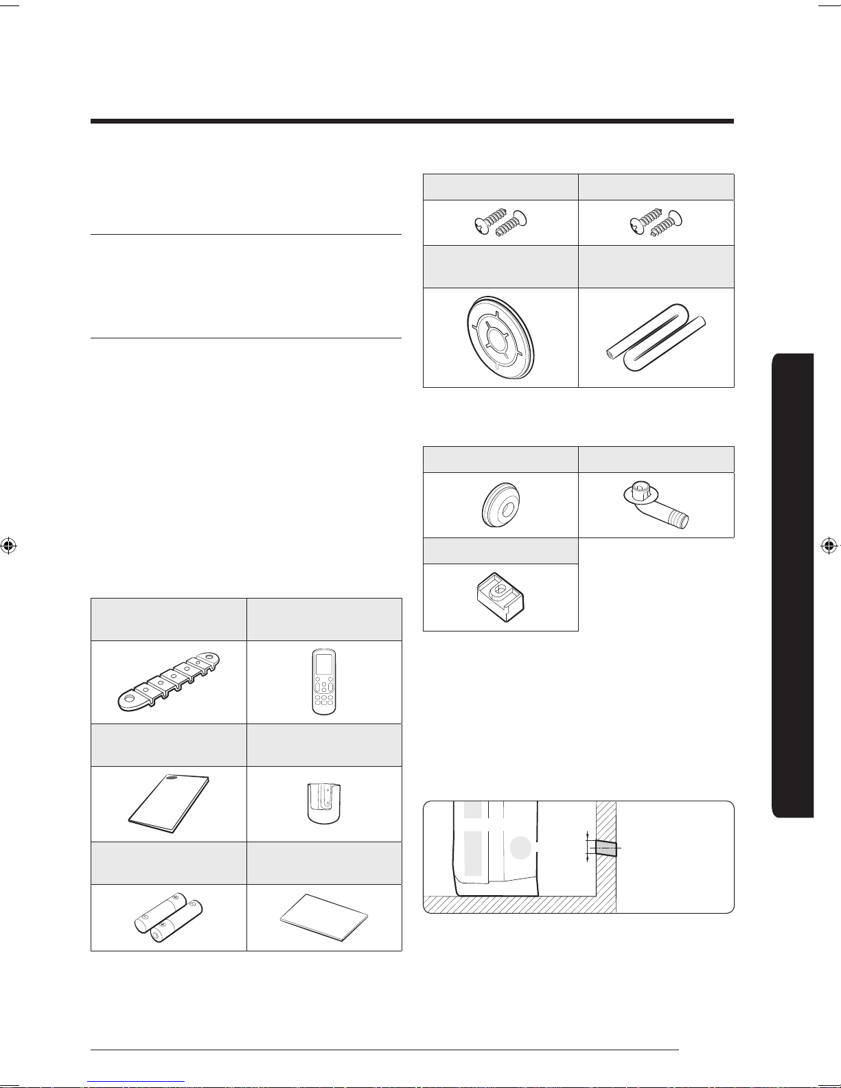
Step 3 Checking and preparing
accessories
The following accessories are supplied with the
air conditioner. Their type and quantity may differ
depending on the specifications.
Accessories in the indoor unit package
Fixing bracket for indoor
unit (1)
Remote control (1)
Pipe outlet protection
rubber (1)
Accessories in the outdoor unit package
Drain cap (3) Drain plug out (1)
Rubber leg (4)
Insulation for drain hose
(1)
Installation Procedure
MANUAL (2)
Batteries for remote
control (2)
Remote control holder
Insulation for piping(1)
(1)
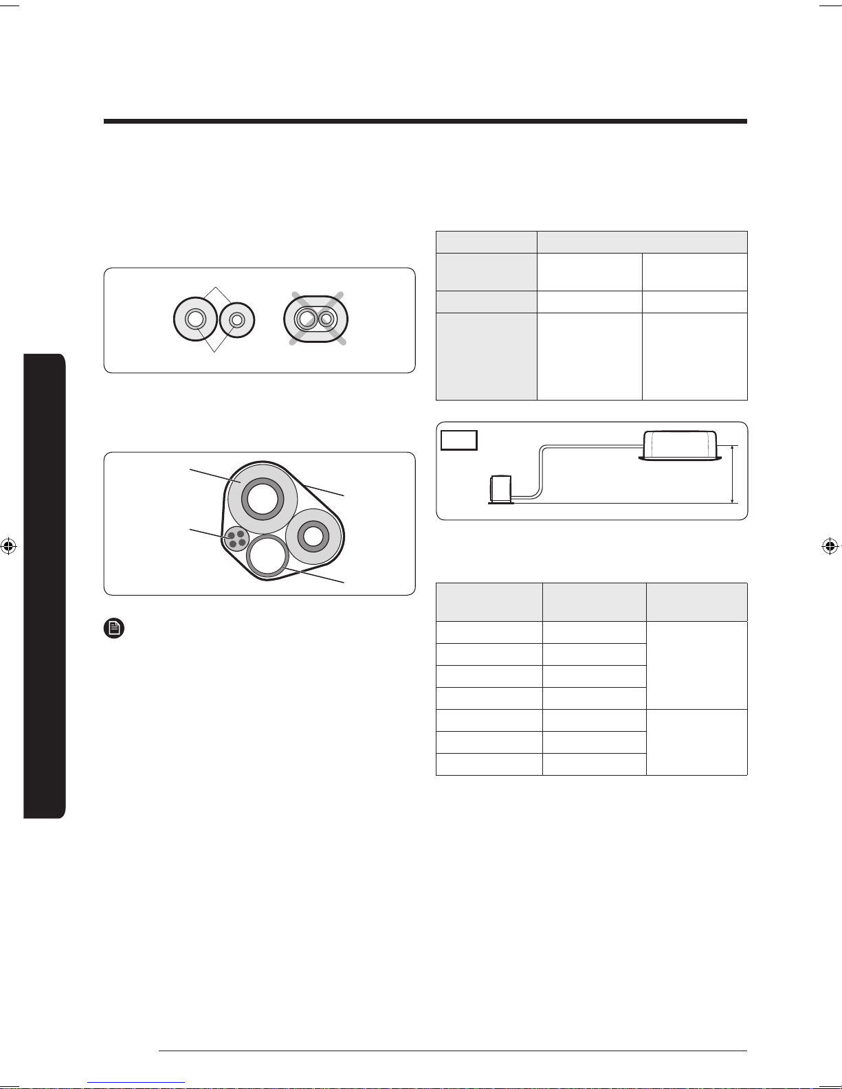
Step 4 Drilling a hole through a wall
1 Determine the position of a 60 to 65 mm hole
considering possible directions of the pipe bundle and
minimum distances between the hole and installation
plate.
2 Drill the hole that slopes slightly downward (15°).
9
Installation Procedure
English
Insulation
Refrigerant pipes
Pipe insulator
Vinyl tape
Drain hose
Indoor/outdoor
unit
communication
cable
L
1
h
1
n=1
indoor
Outdoor
Step 5 Taping the pipes, cables, and
drain hose
Step 6 Connecting the refrigerant
pipes
1 Wrap the refrigerant pipes with the provided
insulation. This wrapping minimises condensation.
Items Maximum allowable length
Outdoor unit
models
AC100KXADEH AC140KXADGH
Main pipe (L1) 50 m 75 m
Max. height
difference
between outdoor
30 m 30 m
and indoor units
2 Wind the refrigerant pipes, power cable,
(h1)
communication cable, and drain hose with vinyl tape
to make a pipe bundle.
Installation Procedure
∙ Temper grade and minimum thickness of the
refrigerant pipe
NOTE
∙ Be sure to insulate the pipes without gaps or cracks,
and use adhesive between the connecting parts of the
insulation to prevent moisture from entering.
∙ When bending the pipe, try to secure a large bending
radius (over 100 mm) to prevent the copper pipe
from distorting.
∙ Use the polyethylene or EPDM foam insulation with a
thickness over 7 mm.
∙ If pipes are installed in a place with humidity
over 80% (such as in a building site pit, basement,
seashore, near hot springs, or lakes), use an insulation
of a thickness over 10 mm.
∙ Make sure that the thickness of the insulation does
not get thinner on the pipe's bending area.
∙ When the insulation thickness becomes thinner, use
extra insulation to maintain thickness.
∙ When installing the pipe hanger, use extra PE- foam
insulation (over 5 mm) to make the width of the
insulation 3 times wider than the hanger. Do not use
cable ties as a pipe hanger.
10
Outer diameter
[mm]
Minimum
thickness [mm]
Temper grade
ø6.35 0.7
ø9.52 0.7
ø12.70 0.8
C1220T-O
ø15.88 1.0
ø15.88 0.8
ø19.05 0.9
C1220T-1/2H OR
C1220T-H
ø22.23 0.9
English
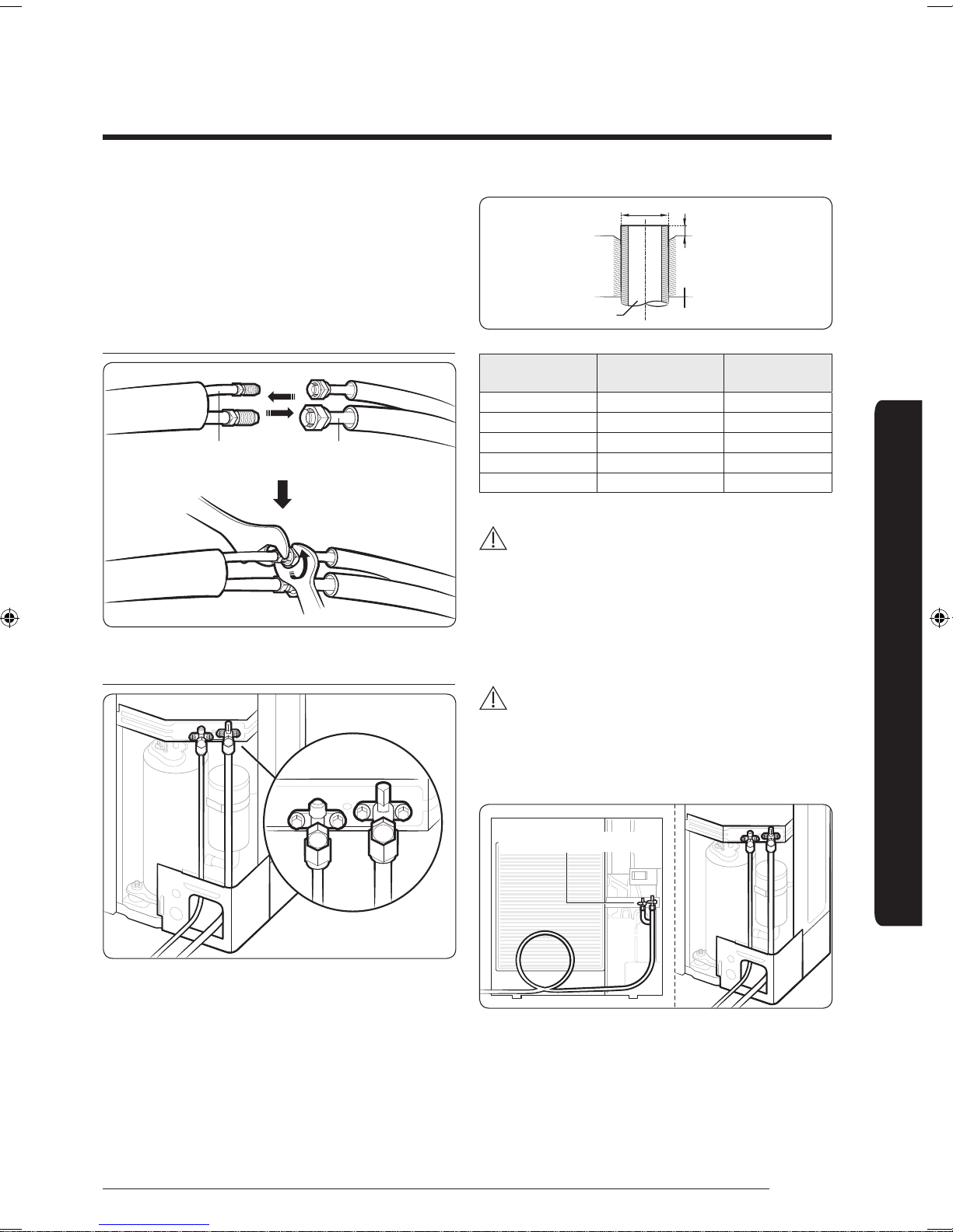
1 Connect each assembly pipe to the appropriate valves
Liquid side
service valve
Gas side
service valve
Liquid
Gas
D
A
Pipe Flare
Make at least one round:
It will reduce noise and vibration
on the indoor and outdoor units and fasten the flare
nuts.
2 As depicted in the illustration below, tighten the flare
nut manually, and then apply the following torque
with a torque wrench.
Indoor unit
Outdoor unit
Outer Diameter
(D, mm)
Fastening torque
(N·m)
Depth (A, mm)
6.35 14 to 18 1.3
9.52 34 to 42 1.8
12.7 49 to 61 2
15.88 68 to 82 2.2
19.05 100 to 120 2.2
WARNING
∙ During installation, make sure that there is no gas
leakage. When collecting refrigerant, first stop the
compressor. If the refrigerant pipe is not properly
connected and compressor runs with the service
valve open, the pipe takes in air and the pressure
rises, which may cause explosion or injury.
Installation Procedure
CAUTION
∙ Be sure to use C1220T-1/2H (Semi-hard) pipe for
more than Ø19.05 mm. If you use C1220T-O (Soft)
pipe for Ø19.05 mm, the pipe may be broken, which
can result in an injury.
∙ The appearance of the unit may be different from the
diagram depending on the model.
11
Installation Procedure
English
90°
Oblique
Rough Burr
Pipe
Reamer
Flaring tool
Correct Inclined Damaged
Surface
Cracked Uneven
Thickness
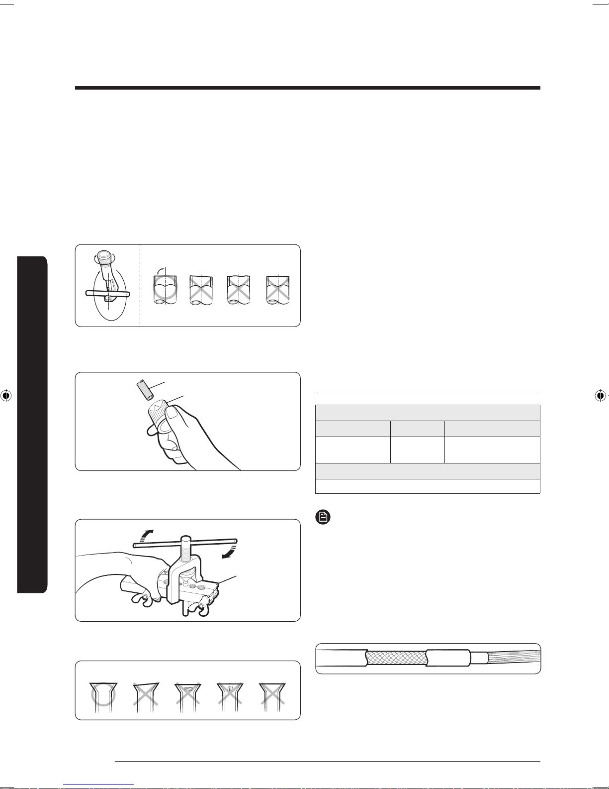
Step 7 Optional: Cutting and flaring
the pipes
1 Make sure that you have the required tools; pipe
cutter, reamer, flaring tool, and pipe holder.
2 If you want to shorten the pipes, cut it with a pipe
cutter, making sure that the cut edge remains at a
90° angle to the side of the pipe. See the illustrations
below for the correct edge cut.
3 To prevent gas leakage, remove all burrs at the cut
edge of the pipe with a reamer.
Installation Procedure
Step 8 Connecting the power and
communication cables
Electrical work must be done by the certified personnel.
∙ Wiring work should be performed in compliance with
related regulations following technical specifications
and installation guide.
∙ Be sure to install an exclusive power supply. If you
use a power strip for multiple electrical connections,
there is a risk of electric shock or fire.
∙ Be sure to install a circuit breaker with a rated current
sensitivity of over 30 mA.
∙ Fasten the screws on the terminal block to be within
the rated range and so that they do not loosen.
∙ Be sure to connect the ground wire. Install the power
wire and make sure it is shorter than 50 m. If the
length of the power wire exceeds 50 m, the product
may not work properly or the wire may be damaged.
Outdoor-to-indoor power and communication
cables specifications
Indoor power supply
Power supply Max/Min (V) Indoor power cable
1Φ, 220-240V,
50 Hz
4 Slide a flare nut onto the pipe.
5 Modify the flare with a flaring tool.
NOTE
∙ For outdoor use, the power supply cords of
the appliances must not be lighter than the
polychloroprene sheathed flexible cord. (Code
designation IEC: 60245 IEC 57 / CENELEC: H05RN-F
or IEC: 60245 IEC66 / CENELEC H07RN-F)
∙ When installing the indoor unit in a computer room
or net work room, use the double shielded (tape
aluminium / polyester braid + copper ) cable of
FROHH2R type.
6 Check that the flaring has been properly made,
referring to the illustrations below.
±10% 2.5 mm² ↑, 3 wires
Communication cable
0.75 to 1.5 mm², 2 wires
12
English
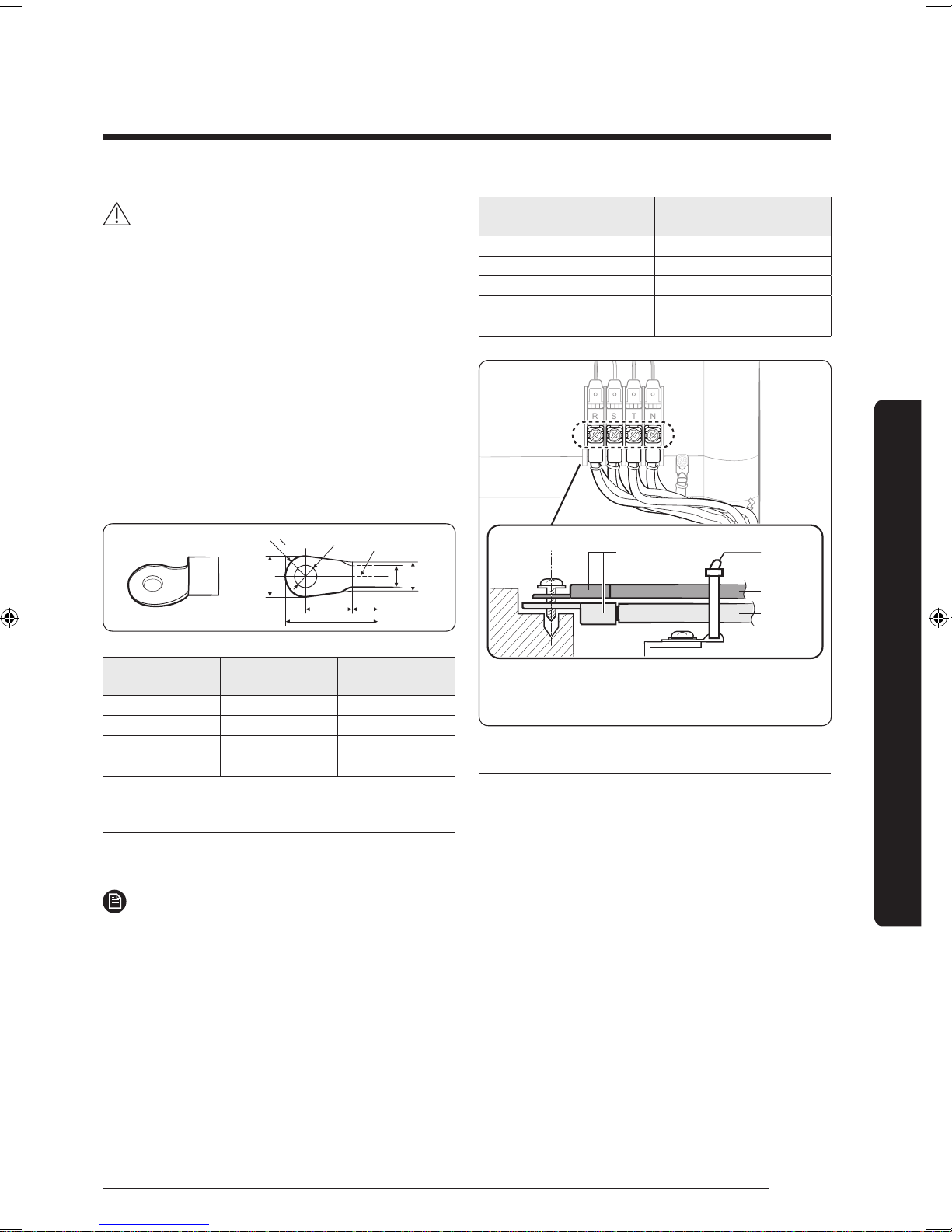
CAUTION
R
B
2
d2
d1
D
B
L
F E
Silver solder
R
S T N
When connecting two cables to a ring terminal, separate the ring
terminal up or down to prevent it from getting loose. Place the thin
cable upward and the thick cable downward. Fix the power cables
with a cable tie.
Solderless ring
terminal
Cable tie
Thin cable
Thick cable
∙ Use rated cables or products only, with heat
resistance over 105°C, as well as properly rated
switches or fuses in the cabinet panel.
∙ Make sure that the cables connected do not produce
sparks around the auxiliary power switch or that
they are not installed in a place subject to high
temperature. High ambient temperature decreases
allowable current.
∙ Install the auxiliary power switch in a dry place,
install the panel board or electrical component box,
and then install the circuit breaker in the panel board.
∙ When connecting the main power cable, press the
cable to the terminal for a secure connection.
∙ Select a ring terminal for use.
Screw
Tightening torque for
terminal (kgf∙cm)
M3 5 to 7.5
M3.5 8 to 12
M4 12 to 18
M5 20 to 30
M6 25 to 37.5
Installation Procedure
Thickness of the
wire (mm2)
B (mm) d2 (mm)
2.5 Less than 9.5 More than 4.5
4 Less than 9.5 More than 4.5
6 Less than 9.5 More than 4.5
10 Less than 15 More than 8.4
Connecting the cable to the power terminal
Connect the cables to the terminal board with the ring
terminals.
NOTE
∙ Be sure to use the certified and rated cables and
firmly connect them without applying any external
force to the ring terminal.
∙ Connect with a driver and wrench that can apply the
rated torque to the screws.
∙ Connect the terminal screws in compliance with the
rated tightening torques.
∙ If the terminal is loose, a fire may occur, caused by
arcing electricity. If the terminal is connected too
firmly, the terminal may be damaged.
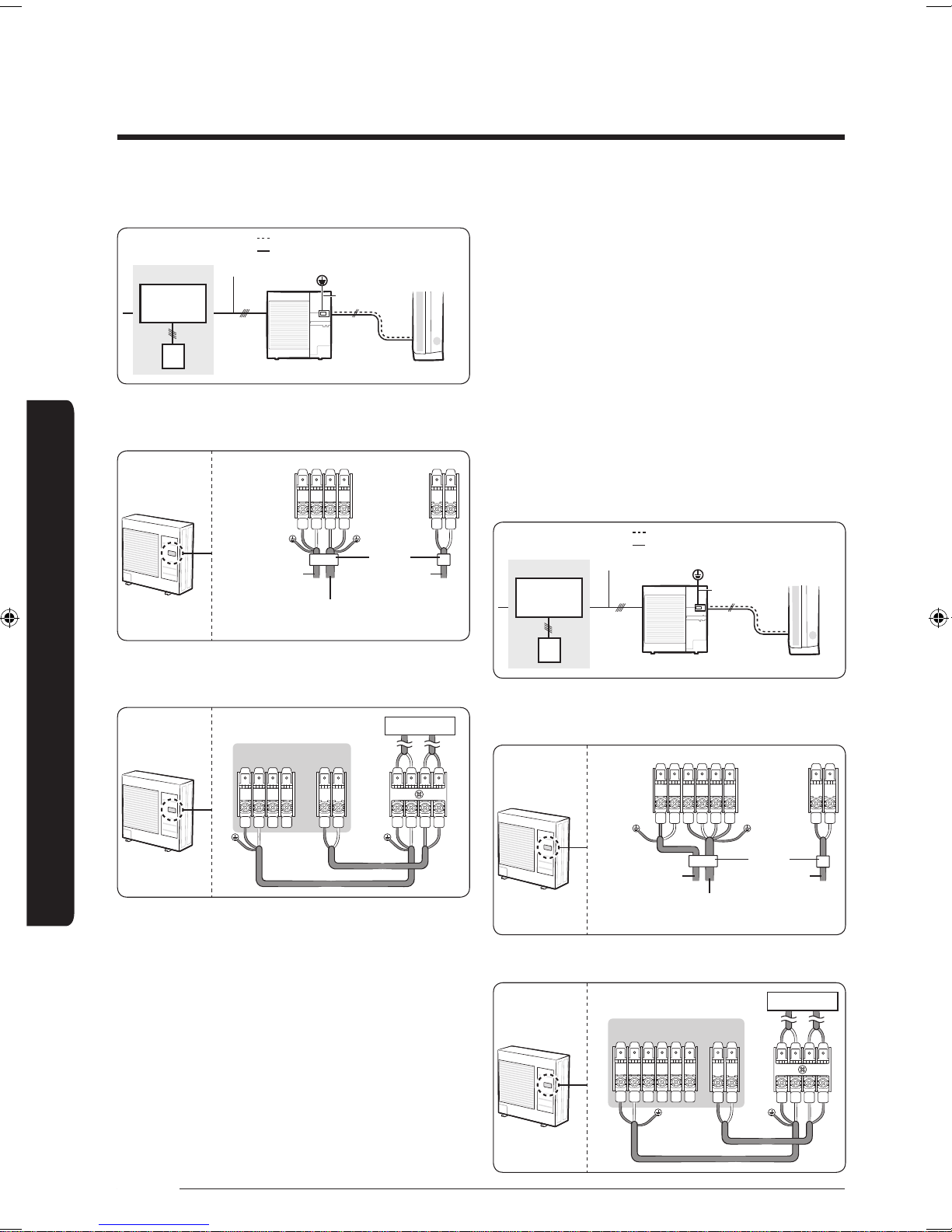
Connecting the cables
AC100KXADEH
∙ This product uses a single phase power, with 220 to 240V
supply.
∙ When connecting the outdoor-to-indoor power cables, be
sure to match the numbers (or letters) between the outdoor
and indoor units. Connect the communication cable to the
connector included in the electrical component box for each
unit. When the outdoor-to-indoor power cables are connected
incorrectly, a malfunction of the product may occur.
∙ When connecting the communication and outdoor-to-indoor
power cables, make sure these cables do not touch the
service valve on the refrigerant pipe on the gas side or the
pipes without proper insulation. Fix the outdoor-to-indoor
power cables to the insulated pipes.
∙ Be sure to comply with the wiring standards, as there may
be a risk of fire.
∙ Make sure to install the circuit breaker firmly inside the
electrical component box.
13
Installation Procedure
English
ELB
NFB Single
phase 220 to
240V, 50 Hz
Outdoor-to-indoor power cable
Main power cable
Outdoor unit Indoor unit
Electrical panel
Earthing
Ground wire
Communication cable
1(L)
2(N) L N
F1 F2
Outdoor-to-indoor
power cable
Communication
cable
cable tie
power supply cable (Single
phase AC 230V, should be
purchased on-site)
1(L)
2(N) L N
F1 F2
1(L) 2(N)
F1 F2
Outdoor unit
Indoor unit
ELB
NFB 3phase 4
wires, 380 to
415V, 50 Hz
Outdoor-to-indoor power cable
Main power cable
Outdoor unit Indoor unit
Electrical panel
Earthing
Ground wire
Communication cable
F1 F2
1(L)
2(N)
L1(R)
L2(S)
L3(T)
N
Outdoor-to-indoor
power cable
Communication
cable
cable tie
power supply cable (Single
phase AC 230V, should be
purchased on-site)
F1 F2
1(L) 2(N) F1 F2
1(L)
2(N)
L1(R)
L2(S)
L3(T)
N
Outdoor unit
Indoor unit
Entire system diagram
∙ When connecting the communication and outdoor-to-
indoor power cables, make sure these cables do not
touch the service valve on the refrigerant pipe on the
gas side or the pipes, without proper insulation. Fix the
outdoor-to-indoor power cables to the insulated pipes.
∙ Make sure to comply with the wiring standards, as
there may be a risk of fire.
∙ Make sure to install the circuit breaker firmly inside
the electrical component box.
∙ Install a 3-phase 4-wire circuit breaker.
∙ When using the power (R, S, T, N) with the NFB
Power wiring diagram
(overcurrent breaker), be sure to connect the main
power cable (R, S, T, N) to the R, S, T and N terminal on
the outdoor unit.
Entire system diagram
Installation Procedure
Indoor and outdoor unit connection diagram
AC140KXADGH
∙ This product uses a 3-phase 4-wire electrical system,
with 380 to 415V supply.
∙ When connecting the outdoor-to-indoor power cables,
be sure to match the numbers (or letters) between the
outdoor and indoor units. Connect the communication
cable to the connector included in the electrical
component box for each unit. When the outdoorto-indoor power cables are connected incorrectly, a
malfunction of the product may occur.
14
Power wiring diagram
Indoor and outdoor unit connection diagram
 Loading...