

Samsung AC026NNNDKH, AC052NNNDKH, AC035NNNDKH, AC071NNNDKH, AC026MXADKH Service Manual
...
SYSTEM AIR CONDITIONER
Mini 4 WAY CASSETTE SERIES
INDOOR UNIT OUTDOOR UNIT
Model :
AC026NNNDKH
AC035NNNDKH
AC052NNNDKH
AC060NNNDKH
AC071NNNDKH
AC026MXADKH
AC035MXADKH
AC052MXADKH
AC060MXADKH
AC071MXADKH
AIR CONDITIONER CONTENTS
AC026MXADKH
AC035MXADKH
AC071MXADKH
AC026NNNDKH
AC035NNNDKH
AC052NNNDKH
AC060NNNDKH
AC071NNNDKH
AC052MXADKH
AC060MXADKH
1. Precautions
2. Product Specifications
3. Disassembly and Reassembly
4. Troubleshooting
5. PCB Diagram
6. Wiring Diagram
7. Reference Sheet

Contents
1. Precautions .................................................................................................. 1-1
1-1 Precautions for the Service ........................................................................................................................... 1-1
1-2 Precautions related to static electricity and PL ..................................................................................... 1-1
1-3 Precautions related to product safety ...................................................................................................... 1-2
1-4 Other precautions ............................................................................................................................................. 1-2
2. Product Specifications ................................................................................ 2-1
2-1 The Feature of Product ................................................................................................................................... 2-1
2-2 Product Specifications (cont.) ...................................................................................................................... 2-2
2-2 Product Specifications (cont.) ...................................................................................................................... 2-4
2-3 Accessories .......................................................................................................................................................... 2-5
3. Disassembly and Reassembly .................................................................... 3-1
3-1 Indoor unit ........................................................................................................................................................... 3-2
3-2 Outdoor unit .....................................................................................................................................................3-10
4. Troubleshooting ......................................................................................... 4-1
4-1 Setting an indoor unit address and installation option .................................................................... 4-1
4-1-1 Common steps for setting the addresses and options ........................................................ 4-1
4-1-2 Setting the indoor unit addresses ................................................................................................. 4-6
4-1-3 Setting the installation options in a batch ................................................................................. 4-7
4-1-4 Changing the addresses and options individually ................................................................. 4-9
4-2 Items to check before diagnostics ...........................................................................................................4-10
4-2-1 Four directions cassette type ........................................................................................................4-10
4-2-2 Test run mode and View mode ....................................................................................................4-11
4-2-3 Troubleshooting for outdoor unit ...............................................................................................4-12
4-2-4 Wired remote controller ..................................................................................................................4-14
4-3 Troubleshooting by symptoms .................................................................................................................4-16
4-3-1 Indoor temperature sensor (open/short) .................................................................................4-16
4-3-2 Indoor heat exchanger temperature sensor (open/short) ................................................4-17
4-3-3 Indoor FAN error .................................................................................................................................4-18
4-3-4 Communication error after finishing Tracking.......................................................................4-19
4-3-5 Indoor unit float sensor error ........................................................................................................4-20
4-3-6 EEPROM circuit failure ......................................................................................................................4-21
4-3-7 Outdoor unit is not powered on – Initial diagnosis ............................................................4-22
4-4 Troubleshooting by symptoms ................................................................................................................4-24
4-4-1 Communication error ......................................................................................................................4-24
2 Samsung Electronics

4-4-2 Outdoor temperature sensor error ............................................................................................4-25
4-4-3 Outdoor Coil temperature sensor error ..................................................................................4-27
4-4-4 Outdoor Discharge temperature sensor error .......................................................................4-29
4-4-5 Outdoor Discharge over temperature error ...........................................................................4-31
4-4-6 Outdoor Fan motor error ................................................................................................................4-32
4-4-7 Compressor starting error ..............................................................................................................4-33
4-4-8 Compressor wire missing error/rotation error .......................................................................4-34
4-4-9 O.C(Over Current) error ...................................................................................................................4-35
4-4-10 DC_link voltage sensor error.......................................................................................................4-36
4-4-11 DC_link voltage under/over error,
Over voltage protection error/PFC over load ......................................................................4-37
4-4-12 DC_link voltage sensor error.......................................................................................................4-38
4-4-13 Current sensor error/Input current sensor error .................................................................4-39
4-4-14 Heatsink sensor error/Heatsink over heat .............................................................................4-40
4-4-15 Comp Vlimit error/Comp current limit error ........................................................................4-41
4-4-16 EEPROM error/OTP error ...............................................................................................................4-42
4-4-17 AC zero cross signal error .............................................................................................................4-43
4-4-18 Operation condition secession error .......................................................................................4-44
4-4-19 Capacity miss match error ...........................................................................................................4-45
4-4-20 Gas leak error .....................................................................................................................................4-46
MDS Error Flow chart .....................................................................................................................4-47
4-4-21
5. PCB Diagram ................................................................................................ 5-1
5-1 Indoor Unit ........................................................................................................................................................... 5-1
5-1-1 MAIN PBA ................................................................................................................................................ 5-1
5-1-2 Display PBA ............................................................................................................................................. 5-3
5-2 Outdoor Unit ....................................................................................................................................................... 5-4
5-2-1 MAIN PBA ................................................................................................................................................ 5-4
5-2-2 Display PBA ............................................................................................................................................. 5-6
6. Wiring Diagram ........................................................................................... 6-1
6-1 Indoor Unit ........................................................................................................................................................... 6-1
6-2 Outdoor Unit ....................................................................................................................................................... 6-2
7. Preference Sheet ......................................................................................... 7-1
7-1 Index of Model Name ...................................................................................................................................... 7-1
7-2 Refrigerating Cycle Diagram ........................................................................................................................ 7-3
7-3 Pressure Graph ................................................................................................................................................... 7-4
Samsung Electronics 3

1. Precautions
1-1 Precautions for the Service
■ Use the standard parts when replacing the electric parts.
– Confirm the model name, rated voltage, rated current of the electric parts.
■ When repairing the equipment, connection of the harness parts must be firm and solid.
– A loose connection may cause noise or other malfunction.
■ When assembling and disassembling the equipment while it is laid down, lay it on soft cloth.
– Otherwise it may scratch the back of the exterior of the product.
■ Remove dust or dirt completely from the housing block, wiring block and service parts during repair.
– This helps prevent the danger of fire caused by tracking or short circuit.
■ Fasten the valve caps of service valves and charging valves of outdoor unit as much as possible using adjustable wrenches.
■ Check the status of the components’ assembly after repair service.
– The status must be the same as before the repair service.
1-2 Precautions related to static electricity and PL
■ The PCB power supply block is susceptible to static electricity. Therefore, care must be taken during repair or measuring
while the power is on.
– Wear insulation gloves for PCB repair or measuring.
Check whether the installation location is at least two meters away from other electronic products such as TV, video, or audio.
■
– Otherwise, the video quality might be degraded or noise might be generated.
■ Do not let end users repair the products themselves.
– Unauthorized disassembly might cause electric shock or fire.
Samsung Electronics 1-1

1-3 Precautions related to product safety
■ Do not pull the power cord and do not touch the power plug or aux power switch with wet hands.
– It might cause electric shock or fire.
■ A damaged power line or power plug must be replaced to prevent danger.
■ Do not bend the power cable with excessive force, and do not place a heavy weight on the case as it might damage the cable.
– It might cause electric shock or fire.
■ Do not use multiple electric outlets.
– This might cause electric shock or fire.
■ C onnect the ground terminal when necessary.
– You must connect the ground terminal if you determine that there is a danger of electric leakage due to moisture or water.
■ Unplug the power cable or turn off the auxiliary power switch for electric part replacement and repair service.
– Otherwise it might cause electric shock.
■ Instruct end users to separate the batteries from the remote controllers and store them separately when the product is not
used for long time.
– Otherwise leakage from the dry cell may cause problems with the remote controller.
1-4 Other precautions
■ The pipes should have no leaks during installation, and the compressor must be stopped before removing connecting pipes
for pump down work. Operating the compressor while the service valve is open and coolant pipe is not properly connected
may cause explosion or injury due to abnormal high pressure created inside the coolant cycle as the air can be absorbed
through the pipe.
■ Pump Down work procedure (When uninstalling the product)
– Turn on the air conditioner, select cooling operation, and run the compressor for more than three minutes.
– Release the high pressure and low pressure valve caps.
– Close the high pressure valve completely using an L-wrench
– After about two minutes, close the low pressure valve completely.
– Stop running the air conditioner.
– Separate the connecting pipe.
1-2 Samsung Electronics

2. Product Specifications
2-1 The Feature of Product
■ Built-in Cassette Type
After installed, the air conditioner can be harmonized with a room interior.
■ High Performance & Energy Saving
With the advanced BLDC inverter technology, it makes a room cool with highly energy saving and arises the efficiency of
air conditioner.
■ Long Ambient Operation(In Low Temperature)
It can arise the reliability and the capacity of the air conditioner, especially operated in low temperature.
■ Eco-friendly Product(Lead-Free, RoHS, WEEE)
■ Easy installation of ultra-lightweight indoor unit
Samsung Electronics 2-1
2-2 Product Specifications (cont.)
ITEM
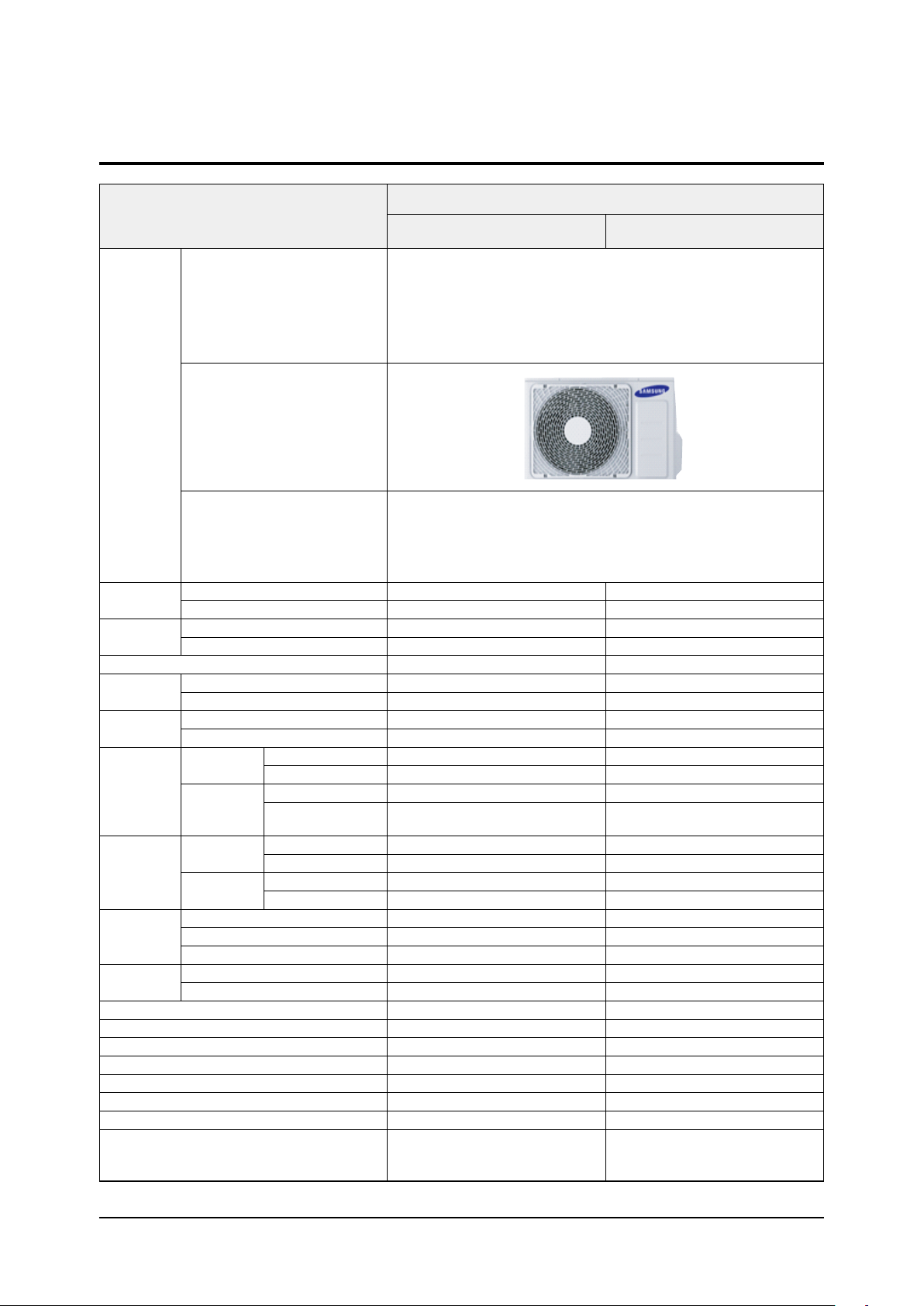
INDOOR UNIT
AC026NNNDKH
AC026MXADKH
Development Model
AC035NNNDKH
AC035MXADKH
IMAGE
Performance
Power
Consumption
Voltage / Frequency
Operating
Current
Noise
Net Dimension
Size
Dimension
Net Weight
Weight
Harness
Specifications
Piping
Factory Charging [g]
Additional Refrigerant (for every 1m) [g]
Basic Piping Length [m]
Max. Piping Length [m]
Max. Level Difference [m]
OUTDOOR UNIT
REMOTE CONTROLLER
Indoor Unit [dBA] (C/H)
Outdoor Unit [dBA] (C/H)
(WxDxH)
Shipping
(WxDxH)
Shipping
Weight
Indoor Fan Motor
Outdoor Fan Motor
High Pressure
PANEL
Refrigerant Type
Option Code
Cooling [W]
Heating [W]
Cooling [W]
Heating [W]
Cooling [A]
Heating [A]
Indoor Unit [mm]
Outdoor Unit [mm]
Indoor Unit [mm]
Outdoor Unit [mm]
Indoor Unit [kg]
Outdoor Unit [kg]
Indoor Unit [kg]
Outdoor Unit [kg]
Compressor
Low Pressure
2,600 3,500
3,400 4,000
680 1,090
900 1,200
1Φ, 220~240V, 50Hz 1Φ, 220~240V, 50Hz
3.8 5.6
4.8 5.8
38/39 41/42
51/51 53/53
575*575*250 575*575*250
790*285*548 790*285*548
623*653*298 623*653*298
926*384*640 926*384*640
11. 4 11. 4
32.8 32.8
13.7 13.7
35.8 35.8
DB31-00578C DB31-00578C
UG9AJ3090FER UG9AJ3090FER
DB31-00642B DB31-00642B
4.1 4.1
1.4 1.4
PC4SUFMAN PC4SUFMAN
R- 410A R- 410A
1,050 1,050
Chargeless Chargeless
5 5
20 20
15 15
01507F-1910C8-271A22-370000
020000-100001-200000-300000
030000-100000-200000-300000
01507F-1930F9-272328-370000
020000-100001-200000-300000
030000-100000-200000-300000
2-2 Samsung Electronics
ITEM
INDOOR UNIT
AC052NNNDKH
AC052MXADKH
Development Model
AC060NNNDKH
AC060MXADKH
IMAGE
OUTDOOR UNIT
REMOTE CONTROLLER
Performance
Power
Consumption
Voltage / Frequency
Operating
Current
Noise
Indoor Unit [dBA] (C/H)
Outdoor Unit [dBA] (C/H)
Net Dimension
(WxHxD)
Size
Shipping
Dimension
(WxHxD)
Net Weight
Weight
Shipping Weight
Harness
Specifications
Piping
Indoor Fan Motor
Outdoor Fan Motor
High Pressure
PANEL
Refrigerant Type
Factory Charging [g]
Additional Refrigerant (for every 1m) [g]
Basic Piping Length [m]
Max. Piping Length [m]
Max. Level Difference [m]
Option Code
Cooling [W]
Heating [W]
Cooling [W]
Heating [W]
Cooling [A]
Heating [A]
Indoor Unit [mm]
Outdoor Unit [mm]
Indoor Unit [mm]
Outdoor Unit [mm]
Indoor Unit [kg]
Outdoor Unit [kg]
Indoor Unit [kg]
Outdoor Unit [kg]
Compressor
Low Pressure
5,000 5,800
5,500 7,000
1,530 2,150
1,520 2,320
1Φ, 220~240V, 50Hz 1Φ, 220~240V, 50Hz
6.9 9.3
6.9 10
43/44 45/46
58/58 58/58
575*575*250 575*575*250
880*310*638 880*310*638
623*653*298 623*653*298
1024*413*73 0 1024*413*730
11. 4 11. 4
43.8 43.8
13.7 13.7
47. 5 47.5
DB31-00578C DB31-00578C
UG9TK3150FE4 UG9TK3150FE4
DB31-00658D DB31-00658D
4.1 4.1
1.4 1.4
PC4SUFMAN PC4SUFMAN
R- 410A R- 410A
1,300 1,300
10 10
5 5
30 30
20 20
01507F-19345D-27343C-370040
020000-100001-200000-300000
030000-100000-200000-300000
01507F-19446E-273C46 -37004 0
020000-100001-200000-300000
030000-100000-200000-300000
Samsung Electronics 2-3

2-2 Product Specifications (cont.)
ITEM
INDOOR UNIT
Development Model
AC071NNNDKH
AC071MXADKH
IMAGE
Performance
Power
Consumption
Voltage / Frequency
Operating
Current
Noise
Net Dimension
Size
Dimension
Net Weight
Weight
Harness
Specifications
Piping
Factory Charging [g]
Additional Refrigerant (for every 1m) [g]
Basic Piping Length [m]
Max. Piping Length [m]
Max. Level Difference [m]
OUTDOOR UNIT
REMOTE CONTROLLER
Cooling [Btu/h]
Heating [Btu/h]
Indoor Unit [dBA] (C/H)
Outdoor Unit [dBA] (C/H)
(WxHxD)
Shipping
(WxHxD)
Shipping
Weight
Indoor Fan Motor
Outdoor Fan Motor
High Pressure
PANEL
Refrigerant Type
Option Code
Cooling [W]
Heating [W]
Cooling [A]
Heating [A]
Indoor Unit [mm]
Outdoor Unit [mm]
Indoor Unit [mm]
Outdoor Unit [mm]
Indoor Unit [kg]
Outdoor Unit [kg]
Indoor Unit [kg]
Outdoor Unit [kg]
Compressor
Low Pressure
6,800
7,500
2,720
2,800
1Φ, 220~240V, 50Hz
11. 8
12.3
46/46
60/60
575*575*250
880*310*798
623*653*298
1023*413*911
11. 4
43.8
13.7
47. 5
DB31-00578C
UG4T200FUAE4
DB31-00658D
4.1
1.4
PC4SUFMAN
R- 410A
1,500
20
5
50
30
01507F-194581-274750 -37004 0
020000-100031-200000-300000
030000-100000-200000-300000
2-4 Samsung Electronics

2-3 Accessories
Item Description Code No. Q’ty Remark
Ass'y drain hose DB94 -03287A 1
Cable-tie DB 65-10 088C 6
Seal-drain ass'y DB62-11028A 1
Seal-drain ass'y DB62-11028H 1
Seal-drain ass'y DB62-11028J 1
USER MANUAL
INSTALLATION MANUAL
CARD WARRNATY DB68-02596B
INSTALLATION MANUAL
Drain Plug
DB68-06489A
DB68-06490A
DB68-05688A
DB67-00 477A
Essential Offer
1
1
1
Essential Offer (Outdoor
1
(Indoor Unit)
Unit)
Rubber Leg DB73-20134A 4
BO LT 6011-003975 4
Essential Offer
(Panel)
INSTALLATION MANUAL
DB 68-03837A 1
Samsung Electronics 2-5

3. Disassembly and Reassembly
■ Necessary Tools
Item Remarks
+SCREW DRIVER
Adjustable Wrench
(8mm, 10mm, 13mm)
M6, M8 Hex Wrench
Samsung Electronics 3-1
3-1 Indoor unit
■ AC026NNNDKH, AC035NNNDKH, AC052NNNDKH, AC060NNNDKH, AC071NNNDKH
No Parts Procedure Remark
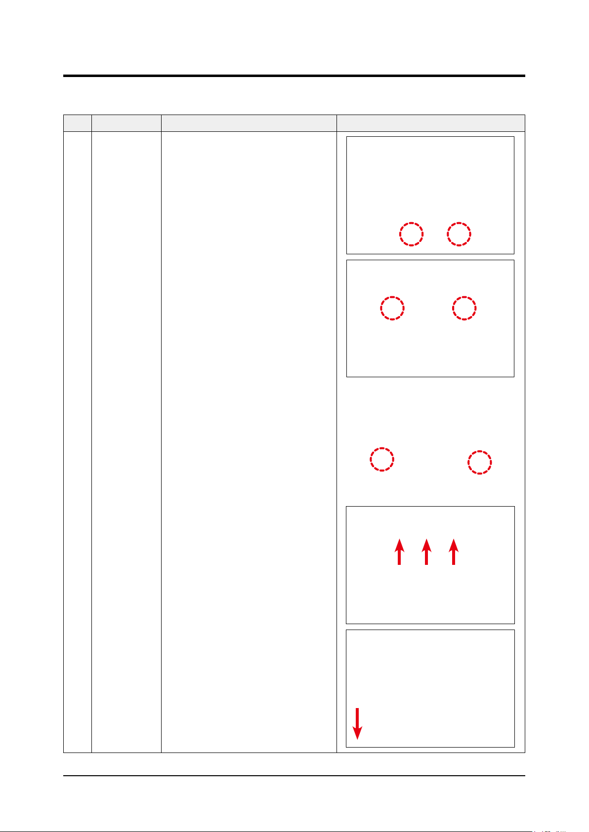
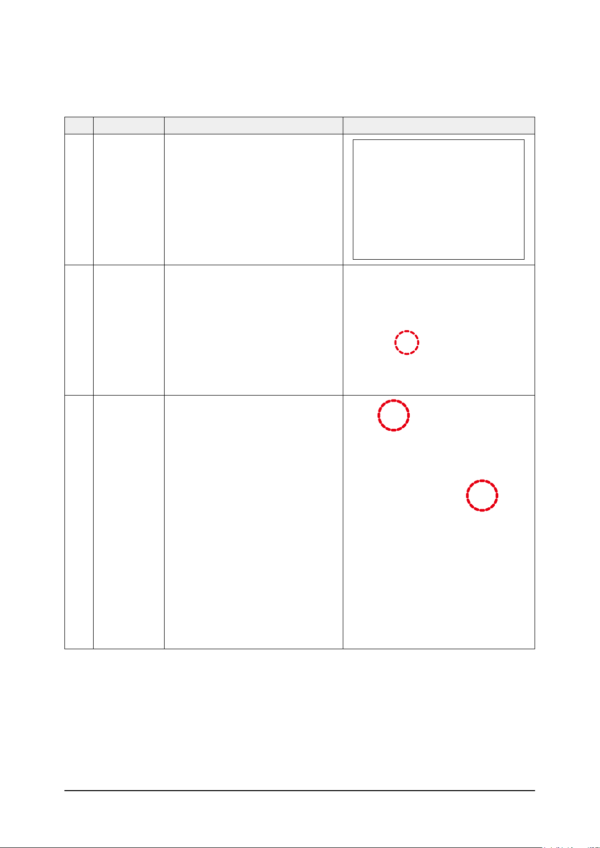
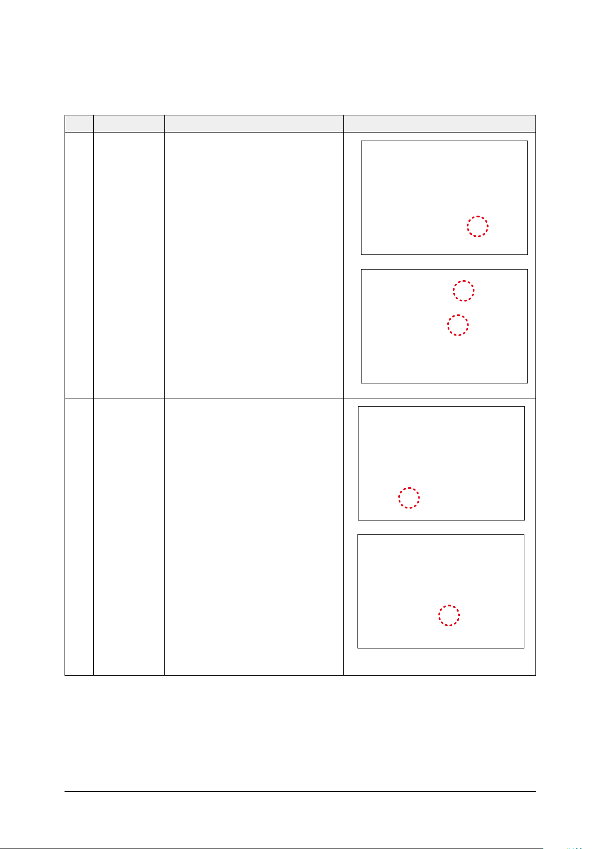
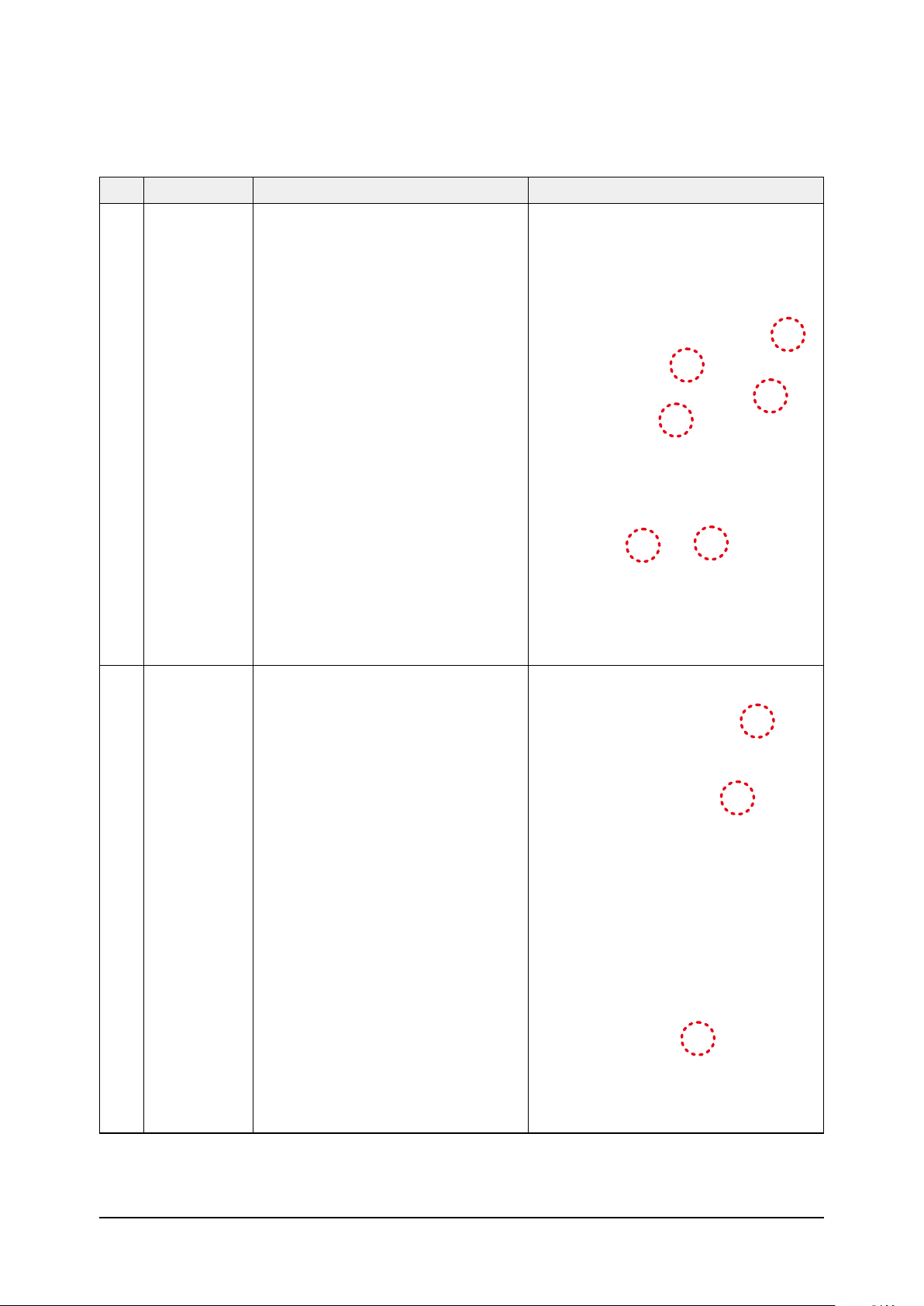
1 Panel 1) Pull both hooks and take the grille downward.
Two safety clips are mounted to the front grille
to prevent it from dropping.
2) Detach the safity clip and take up the grille.
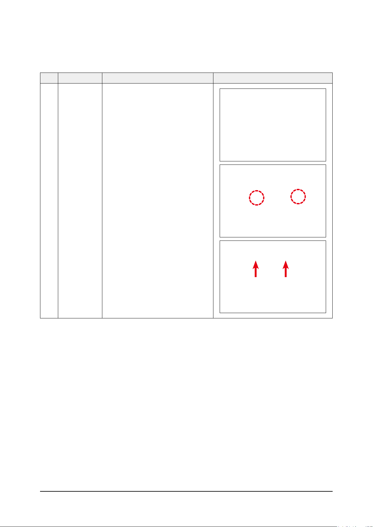
3) Remove the 2 fixed screws to remove the
Control-Box Cover. (Use +Screw Driver)
4) Remove the remote control-receiver , blade
conector and humidity sensor wires from the
PBA. (4EA)
5) Push the 4 panel corners and cover downwards
to remove it.
3-2 Samsung Electronics
No Parts Procedure Remark
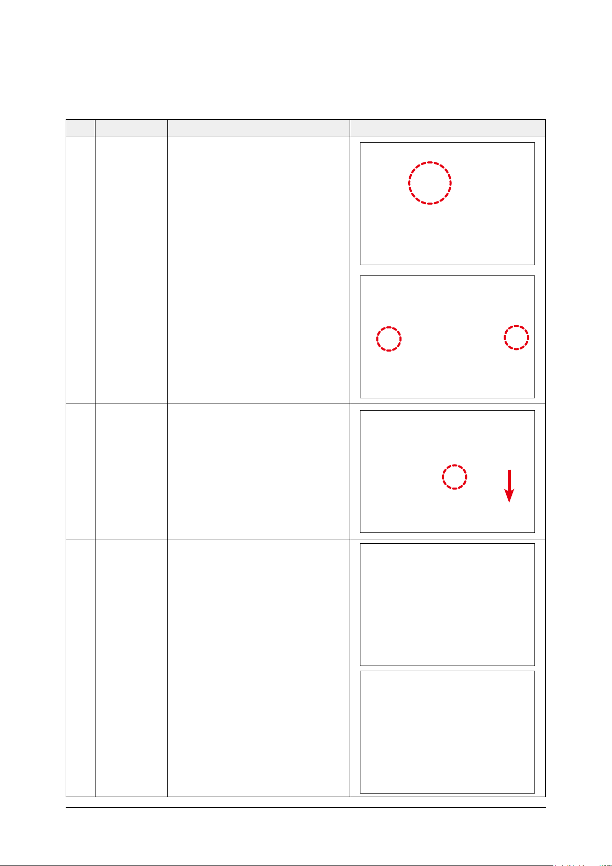
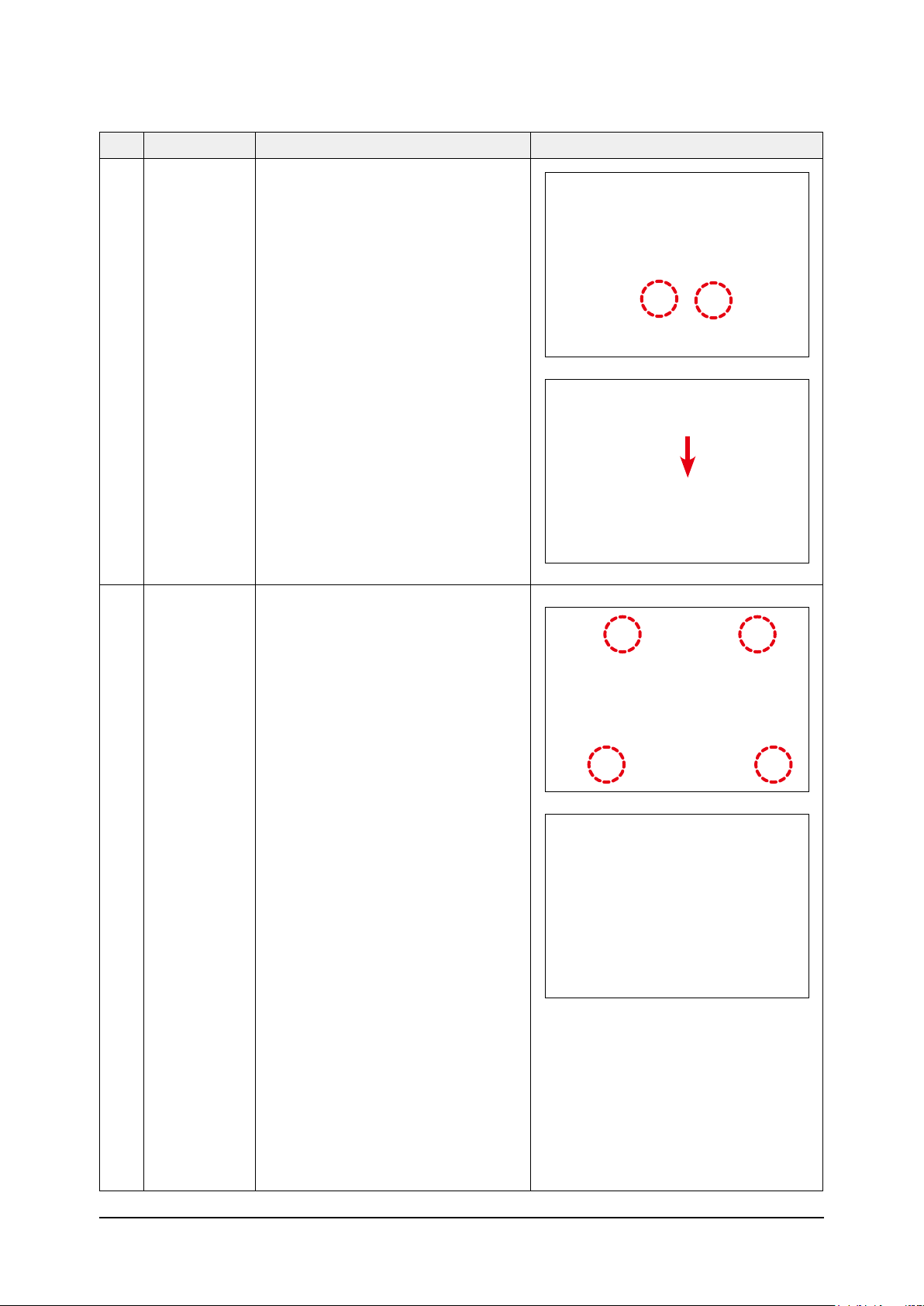
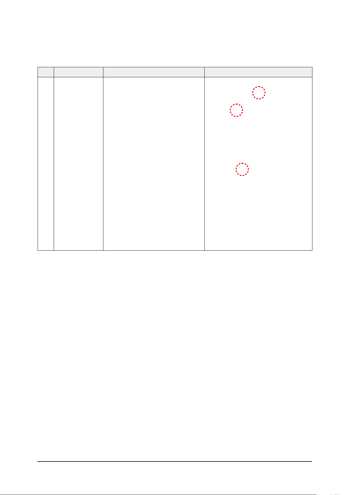
6) Disassemble the bolts that are assembled with
the indoor unit at the 4 panel corners.
7) Press the Hangers at both sides of the panel
inwards, to remove it from the indoor unit’s
hook.
Remove the panel from the indoor unit.
2
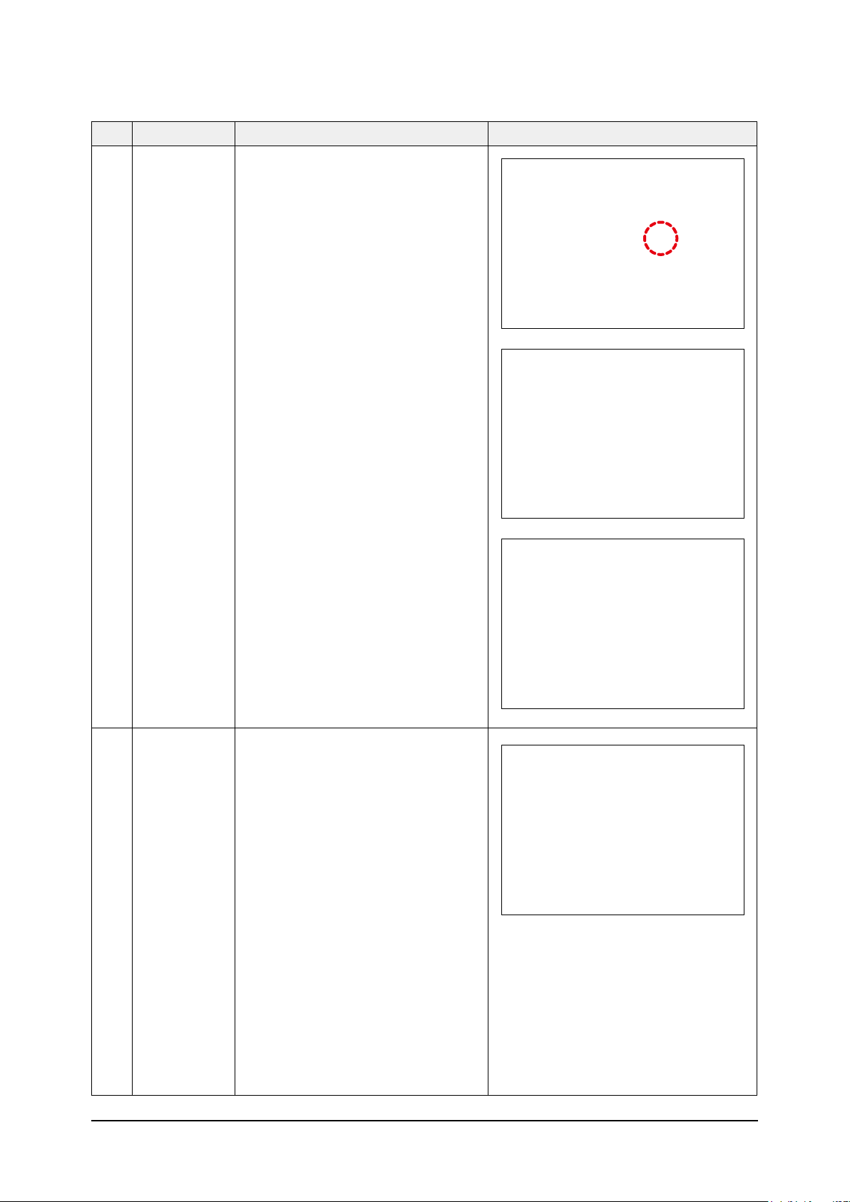
3 Display PBA
Blade 1) Remove the hinge-blade and blade.
1) Remove the cover display.
2) Remove the cover PBA from the cover display.
Samsung Electronics 3-3
No Parts Procedure Remark
3) Disconect the conector wire from the PBA.
Humidity Sensor 1) Remove the humidity sensor from the panel.
4
5
Step motor 1) Unscrew 2 screws on cover motor. (Use +Screw
Driver
2) Remove 2 cover motor.
Remove the 2 fixed screws and disassemble the step
3)
motor. (Use +Screw Driver)
3-4 Samsung Electronics
No Parts Procedure Remark
6 Control-Box 1) Disconnect the Connector Wire that is
connected to the indoor unit’s PBA
2) Unscrew the 2 fixed screws on both sides of the
Control Box, and disassemble the Control Box
from the indoor unit.(Use +Screw Driver)
Samsung Electronics 3-5
No Parts Procedure Remark
7 Bell-Mouth 1) Unscrew the screw fixed on the Bell-Mouth.
(Use +Screw Driver)
2) Push the Bell-Mouth in the direction
opposite to where it’s installed on the
Control-Box to remove it.
8 Drain Pan 1) Unscrew the screws on the 4 corners
of the indoor unit. (Use +Screw Driver)
2) Remove the Drain Pan from the indoor unit.
3-6 Samsung Electronics
No Parts Procedure Remark
9 Drain Pump
&
Hose
1) Remove the 2 fixed screws and
disconnect the white drainage hose from
the Drain Pump. (Use +Screw Driver)
2) Remove the 2 screws and take the
Drain-Hose out from the indoor unit to
disassemble the transparent Drain-Hose
fixed on the side of the indoor unit.
(Use +Screw Driver)
10 Evap.
Temperature
Sensor
1) Use your hand to remove the temperature
sensor attached to the Evap Pipe along with
the fixing clip.
Samsung Electronics 3-7
No Parts Procedure Remark
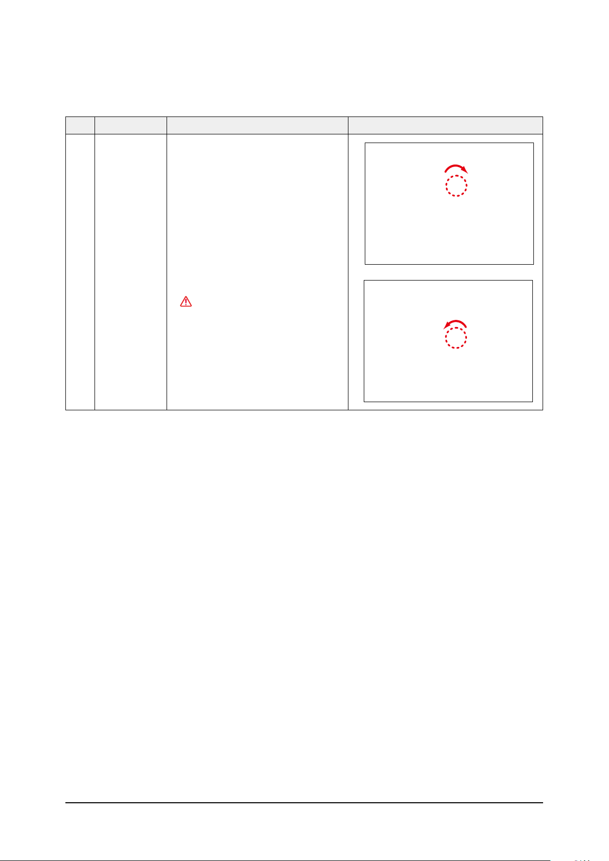
11 Fan
&
Motor
1) Turn the hexangular nut attached to the
top of the Fan counterclockwise to remove it.
Take the Fan out of the Motor.
2) Turn the three hexangular nuts on the
Motor counterclockwise to remove the nuts.
Take the Motor Wires attached to these
three locations out with your hands prior to
removing the Motor.
12 Evaporator 1) Remove the screws of the Steel Holder Evaps
that are used to fix the Heat Exchanger, and
then remove it. (Use +Screw Driver)
2) Remove the 2 fixing screws of the Partition
Evap at the Heat Exchanger’s In/Out Pipe.
(Use +Screw Driver)
3-8 Samsung Electronics

No Parts Procedure Remark
3) Remove the screw of the Cover Pipe
that is used to fix the In/Out Pipe.
Remove the In/Out Pipe. (Use +Screw Driver)
4) Remove the Heat Exchanger from the
indoor unit’s cabinet.
Samsung Electronics 3-9
3-2 Outdoor unit
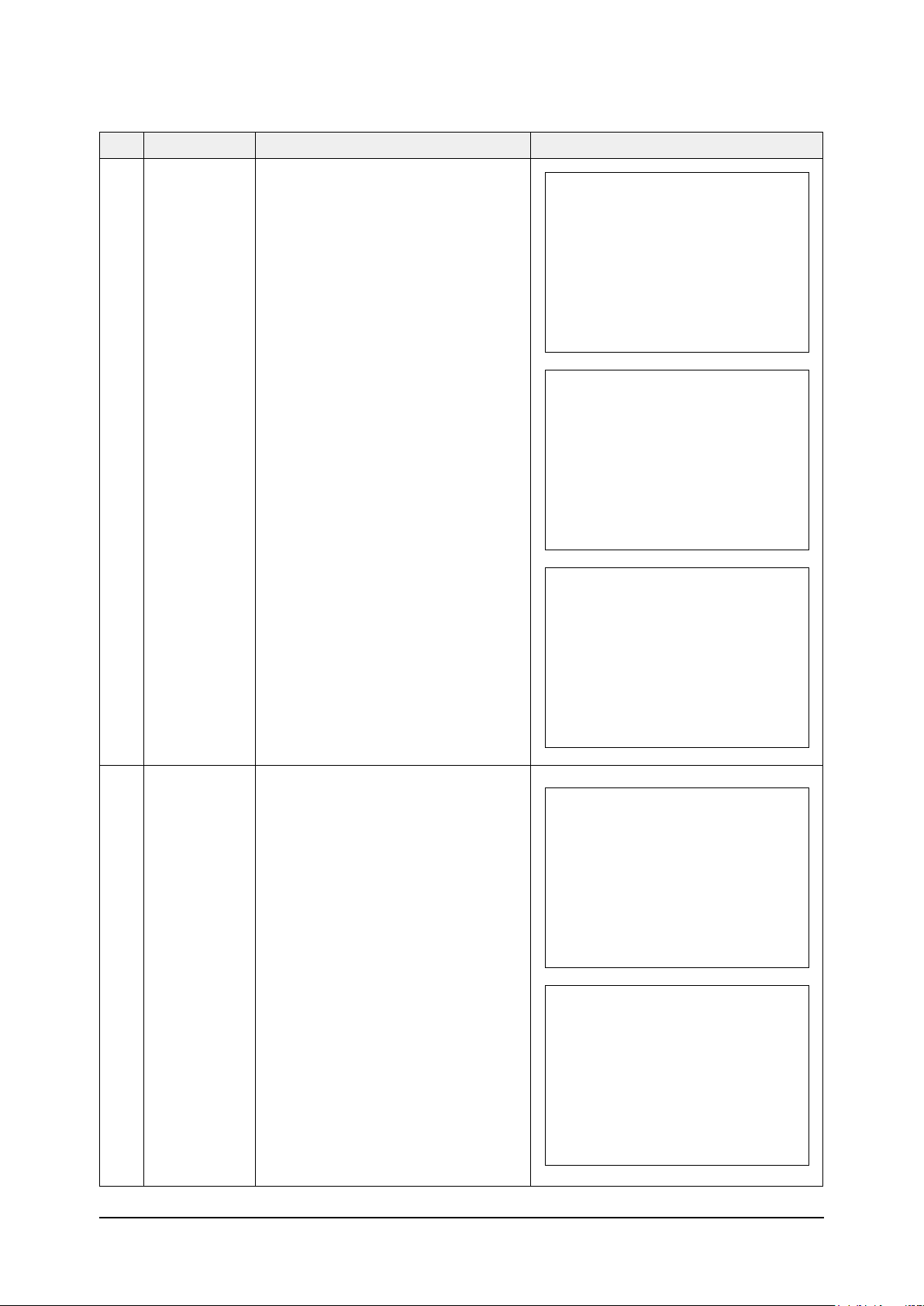
■ AC026MXADKH / AC035MXADKH
No Parts Procedure Remark
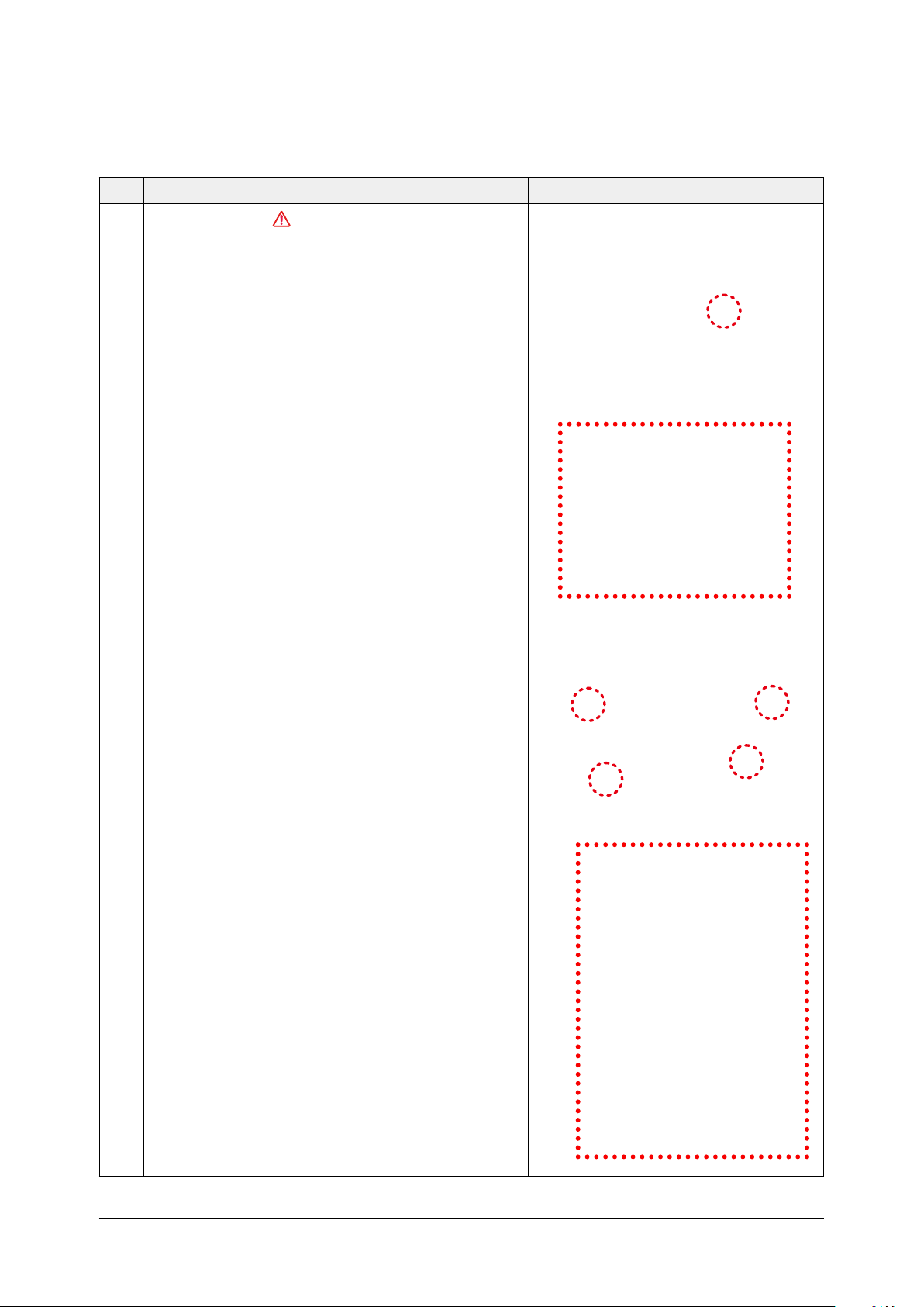
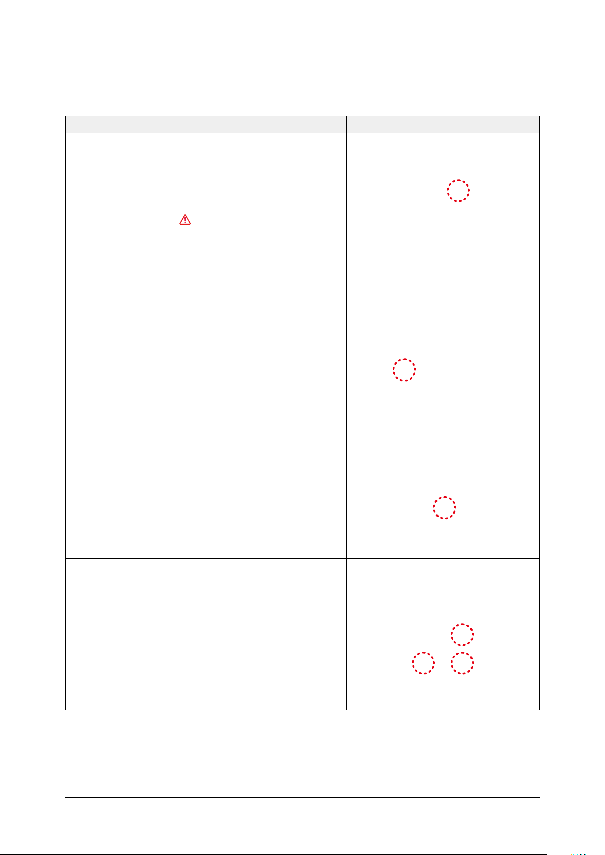
1 common work You must turn off the Power
CAUTION
before disassembly.
1) loosen 1 pcs screw of cover control,and
detach it.
2) loosen 5 pcs screws on both right and
left cabniet side edges and to detach the
cover-top
3) Loosen 7 screwsfixed to disassemble
cabi-front , and detach it.
3-10 Samsung Electronics
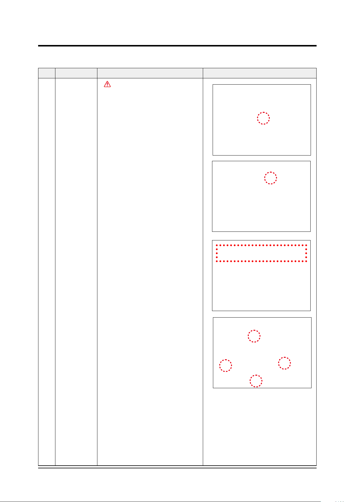
No Parts Procedure Remark
common work
4) loosen 2 screws to disassemble steel-bar.
5) Loosen 2 screws to disassemble the cabi left
and detach it.
Samsung Electronics 3-11
No Parts Procedure Remark
common work 6) Loosen 7 screws to disassemble the cabi right
and detach it.
2 fan&motor 1) loosen 1 screw as indication and detached
the fan.
2) loosen 4 pcs motor screws and disconnect
the wire betwwen assy control out and motor.
3) loosen 2 pcs bracket-motor screw and
detach it.
3-12 Samsung Electronics
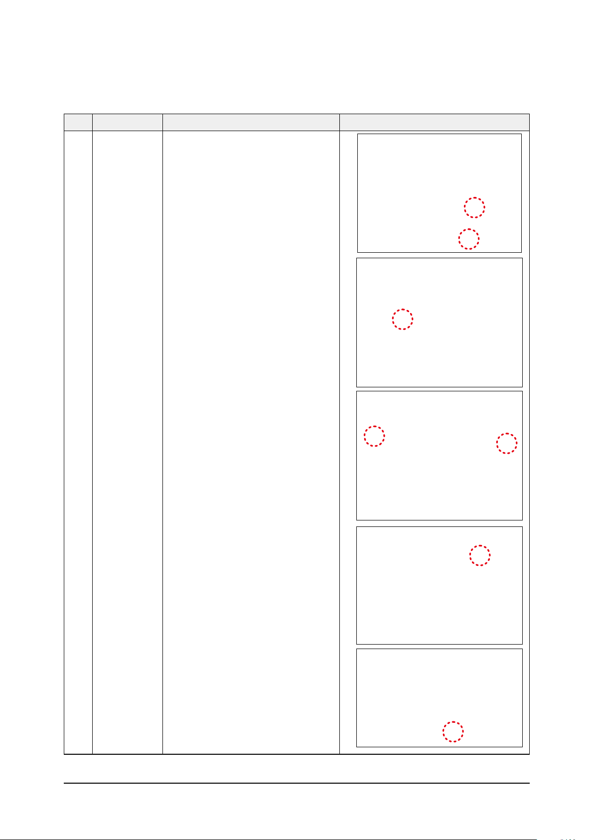
No Parts Procedure Remark
3 assy control out 1) lossen fixing 1 screw from cover -control
2) detach several connections from assy control
out, take out assy control out.
4 Heat exchanger 1) Release the refrigerant at first
2) Looosen fixing screw on both side.
3) disaessembly the pipes in both inlet and
outlet with welding torch.
4) detach the heat exchanger.
Samsung Electronics 3-13
No Parts Procedure Remark
CAUTION
5 compressor 1) disconnect the compressor lead wire .
2)disassembly the felt comp sound.
loosen the 3 bolts at the bottom .
When removing the compres-
sor, Heat Exchanger, and Pipe, purge the
Coolant inside the Compressor completely
and remove the pipe with a welding flame.
3-14 Samsung Electronics
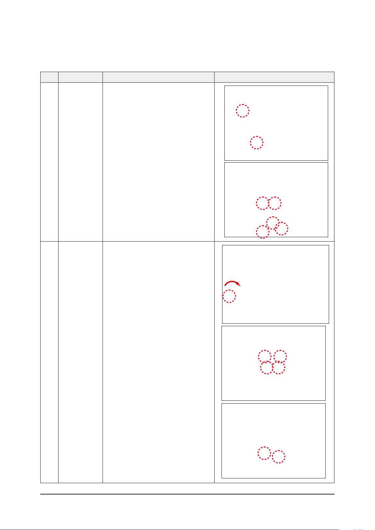
■ AC052MXADKH / AC060MXADKH
No Parts Procedure Remark
1 common work You must turn off the Power before
CAUTION
disassembly.
1) Loosen 1 pcs screw of cover control
2) Loosen 8 pcs screw of the cabi top
cover.
3) Loosen 4 pcs screw of the bar steel.
4) Loosen 10 pcs screw of the cabi side
front.
Samsung Electronics 3-15
No Parts Procedure Remark
1 common work
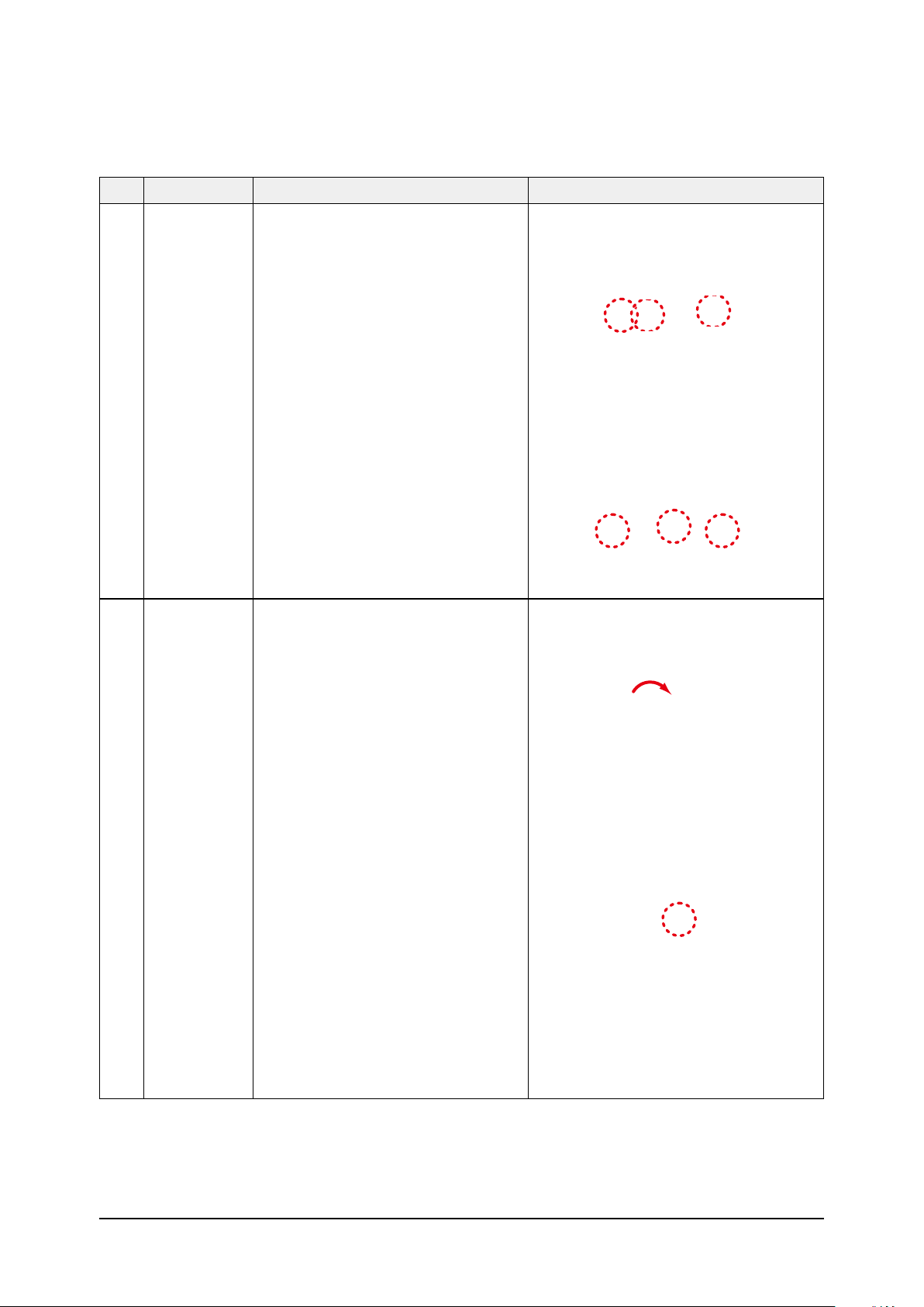
2 Fan& motor 1) Loosen the fan screw according the indi
-
cation and detach the fab propeller
2)Disconnect the wire between assy control out
and motor.
3-16 Samsung Electronics
No Parts Procedure Remark
2
3) Loosen 4 pcs motor screw.
4) Loosen 2 pcs screw of bracket motor.
3 Assy control out
1)Loosen the screws that connected partition
and case control then get the control out.
2) Loosen the screw of the cover termimal
Samsung Electronics 3-17
No Parts Procedure Remark
3
3) Loosen 2 screws , disassemble the Coil
Harmonic.
4) Loosen the screw of the cover terminal.
3-18 Samsung Electronics
No Parts Procedure Remark
CAUTION
4 Heat exchanger 1) Release the refrigerant at first
2) Loosen fixing screw on both side..
3) Disassemble the pipes in both inlet and
outlet with welding torch.
4) Detach the heat exchanger.
When removing the compres-
sor, Heat Exchanger, and Pipe, purge the
Coolant inside the Compressor completely
and remove the pipe with a welding flame.
5 Compressor
1)Loosen the 3 bolts at the bottom of compres-
sor.
Samsung Electronics 3-19
 Loading...