

Samsung AC036KXQPCC, AC048KNPPCC, AC036KNPPCC, AC048KXQPCC, AC140KNPDEH Service Manual
...
AIR CONDITIONER
CONTENTS
FLOOR STAND TYPE AIR CONDITIONER
Basic : AF55JV1MAEE
CCPQXK840CA / CCPPNK840CA : ledoM
AC036KNPPCC / AC036KXQPCC
AC140KNPDEH / AC140KXADGH
AC100KNPDEH / AC100KXADEH
AC048KNPDEC / AC048KXADGC
AC036KNPDEC / AC036KXADEC
Model Code : AC048KNPPCC/MG AC048KXQPCC/MG
AC036KNPPCC/MG AC036KXQPCC/MG
AC140KNPDEH/EU AC140KXADGH/EU
AC100KNPDEH/EU AC100KXADEH/EU
AC048KNPDEC/TL AC048KXADGC/TL
AC036KNPDEC/TL AC036KXADEC/TL
1. Precautions
2. Product Specications
3. Disassembly and Reassembly
4. Troubleshooting
5. PCB Diagram
6. Wiring Diagram
7. Reference Sheet
AC048KXQPCC
AC036KXQPCC
AC140KXADGH
AC048KXADGC
AC048KNPDEC/SV AC048KXADGC/SV
AC048KNPPCC
AC036KNPPCC
AC140KNPDEH
AC100KNPDEH
AC048KNPDEC
AC036KNPDEC
AC100KXADEH
AC036KXADEC

Contents
1. Precautions ······································································································································· 1-1
1-1 Precautions for the Service ············································································································ 1-1
1-2 Precautions for the Static Electricity and PL ··············································································· 1-1
1-3 Precautions for the Safety ·············································································································· 1-1
1-4 Others ················································································································································ 1-1
2. Product Specifications ·············································································································· 2-1
2-1 The Feature of Product ··················································································································· 2-1
2-1-1 Features ·································································································································· 2-1
2-1-2 Changes in comparison to basic model ············································································ 2-2
2-2 The Comparative Specifications of Product ················································································ 2-3
2-3 Accessory and Option Specifications ··························································································· 2-5
2-3-1 Filter·········································································································································· 2-5
2-3-2 Accessory ································································································································· 2-5
3. Disassembly and Reassembly ······························································································ 3-1
3-1 Indoor Unit ······································································································································· 3-2
3-2 Outdoor Unit ···································································································································· 3-10
4. Troubleshooting ···························································································································· 4-1
4-1 Indoor Display Error and Check Method ····················································································· 4-1
4-1-1 Indoor unit LED display at error detecting ······································································· 4-1
4-2 Outdoor Trouble shooting ············································································································· 4-2
4-3 Troubleshooting by symptoms ····································································································· 4-5
4-3-1 Communication error after finishing tracking (E202) ······························································ 4-5
4-3-2 Outdoor's service valve(Clog) ············································································································ 4-6
4-3-3 No Power(completely dead) - Initial diagnosis ································································· 4-7
4-3-4 E102 : Communication error between indoor and outdoor unit
E201 : Unit quantity miss matching beween Indoor and Outdoor
E202 : Abnormal state, no communication between Indoor and Outdoor Main PCB
E203 : 1min Time out of communication error(MainļInverter) ········································· 4-11
4-3-5 External Sensor Error (Error Code: E221, E231, E251, E320) ·················································· 4-12
4-3-6 E403 : Freezing control causes comp. down ··············································································· 4-13
4-3-7 E416 : Dischage temperature sensor error ··················································································· 4-14
4-3-8 E440, E441 : Abnormal outside temperature halts operation of the compressor ······· 4-15
4-3-9 Outdoor unit BLDC Fan1 or Fan2 error (E458 : Fan1 error, E475 : Fan2 error) ··············· 4-16

Contents
4-3-10 E461: Compressor start error
E467: Compressor wire missing error ·························································································· 4-17
4-3-11 E462 : Current protection control causes comp. down
E484 : PFC overload error ·················································································································· 4-18
4-3-12 E463 : OLP protection control caused comp. down ······························································ 4-19
4-3-13 E464 : O.C. (Over Current) error······································································································· 4-20
4-3-14 E466: DC Link Over voltage/ Low voltage error······································································· 4-21
4-3-15 Pipe Blocking Error (Error Code: E422) ························································································ 4-22
4-3-16 The others ················································································································································ 4-23
4-3-17 Setting an indoor unit installation option ················································································· 4-24
5. PCB Diagram ··································································································································· 5-1
5-1 Indoor unit ········································································································································ 5-1
5-1-1 Main PCB ································································································································ 5-1
5-1-2 Power PCB ······························································································································ 5-3
5-1-3 Panel PCB ································································································································ 5-4
5-2 Outdoor unit ···································································································································· 5-5
5-2-1 Main PCB Diagram ················································································································ 5-5
5-2-2 Inverter PCB ··························································································································· 5-6
5-2-3 EMI PCB ··································································································································· 5-10
6. Wiring Diagram ····························································································································· 6-1
6-1 Indoor unit ········································································································································ 6-1
6-2 Outdoor unit ···································································································································· 6-2
7. Reference Sheet ···························································································································· 7-1
7-1 Index for Model Name ···················································································································· 7-1
7-2 Refrigerating Cycle Diagram ·········································································································· 7-2

Samsung Electronics 1-1
1. Precautions
1-1 Precautions for the Service
O Use the standard parts when replacing the electric parts.
– Confirm the model name, rated voltage, rated current of the electric parts.
O Repair the disconnection of HARNESS securely when repairing the break down.
– If there is any connection error, it causes an abnormal noise and incorrect operation.
O In case that you assemble or disassemble the products with laying it on the side, do work on the work cloth.
– If not, the exterior of products can be scratched.
O
Remove dust and foreign materials from harness, connection part, and inspection part thoroughly when repairing the break down.
– It protects the danger of fire such as tracking and short.
O Tighten tightly the service valve of outdoor unit and the cap of charging valve with a monkey spanner.
O Check the assembly status of parts after repairing the break down.
– It should be same as the status before repairing.
1-2 Precautions for the Static Electricity and PL
O As the PCB power terminal has a weakness for the static electricity, pay attention to it during the repair and measurement.
– Work with insulation gloves during the repair and measurement of PCB.
O
Check the distance between the product and the other electronic appliances such as TV, video, and audio. It should be over 2m.
– If not, it causes a bad picture quality or a noise.
O Repairing the products by consumer should be strictly prohibited.
– There is a danger of electric shock or fire due to incorrect disassembly.
1-3 Precautions for the Safety
O Do not pull any electric wires and do not touch an auxiliary power switch with a wet hand.
– There is a danger of electric shock or fire.
O In case any wire or power plug has been damaged, replace it to eliminate any possible danger.
O Do not bend the power cord by force and do not put any heavy object on the power cord.
– There is a danger of electric shock or fire.
O Do not use multi socket.
– There is a danger of electric shock or fire.
O Ground the product if necessary.
– Be sure to ground the product if there is any danger of electric leakage due to water or moisture.
O Be sure to turn off the auxiliary power switch or pull out the power plug during replacement or repair of electric parts.
– There is a danger of electric shock.
O In case the product will not be in use for a long time, the battery of remote control should be kept separately.
– Leakage of inside fluid can cause break down of remote control.
1-4 Others
O Never store or load the air conditioner upside down or sideways to prevent the damage to the compressor.
O Young children or infirm persons should be always supervised when they use the air conditioner.
O Max current is measured according to IEC standard for safety.
O Current is measured according to ISO standard for energy efficiency.
O
When installing, make sure there is no leakage. When recovering the refrigerant, ground the compressor first before removing the
connection pipe. If the refrigerant pipe is not properly connected and the compressor works with the service valve open, the pipe
inhales the air and it makes the pressure inside of the refrigerant cycle abnormally high. It may cause explosion and injury.
O Pump Down Procedure (When removing the product)
- Turn on the air conditioner and select Cool mode to run the compressor for 3 minutes.
- Release the valve caps on High and Low pressure side.
- Use L wrench to close the valve on the high pressure side.
- Approximately 2 minutes after, close the valve on the low pressure side.
- Stop operation of the air conditioner.
- Disconnect the pipes.

Product Specifications
Samsung Electronics 2-1
2. Product Specifications
2-1 The Feature of Product
2-1-1 Features
O Strong Turbo/convenient long-distance operation
Quicker and more consistent air cooling/warming is guaranteed by turbo operation that provides strong
cooling/warming for 30 minutes or by long-distance operation that ensures cooling/warming even in places a
long way from the air conditioner.
O Stylish, high quality design
Neat and luxurious style boasts high-quality interior design that ts naturally into any place.
O Compact Remote Controller
A small hand-size remote control makes it even easier to use.
O Long Piping(Length & Height)
It can give the benet to the installers and aries the reliability of the air conditioner.
O Long Ambient Operation(In Low Temperature)
It can arise the reliability and the capacity of the air conditioner, especially operated in low temperature.
O Eco-friendly Product (Lead-Free, RoHS, WEEE)
O
High Performance & Energy Saving
With the advanced BLDC inverter technology, it makes a room cool with highly energy saving and arises the efficiency of air
conditioner.
Product Specifications
2-2 Samsung Electronics
Changed part Changed item and feature Basic After changed
Indoor Unit Wi-Fi Function added.
Outdoor Unit
(AC048KXQPCC
AC036KXQPCC
AC140KXADGH
AC048KXADGC)
Inverter controller changed.
Outdoor Unit
(AC100KXADEH
AC036KXADEC)
--
2-1-2 Changes in comparison to basic model
2-3 Samsung Electronics
Product Specifications
Samsung Electronics 2-4
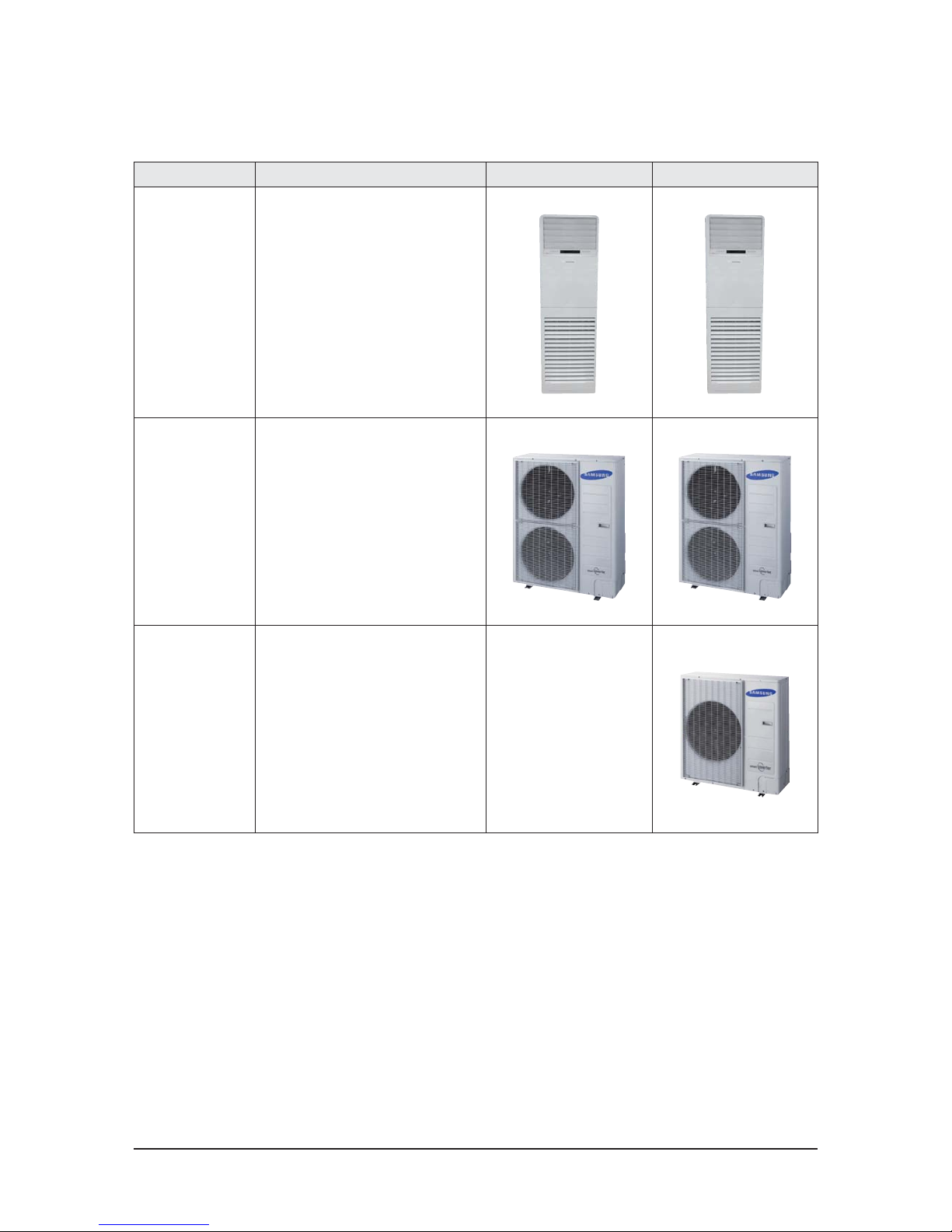
Item
Development Model Basic Model
AC048KNPPCC
AC048KXQPCC
AC036KNPPCC
AC036KXQPCC
AC140KNPDEH
AC140KXAPGH
AC100KNPDEH
AC100KXAPEH
AC048KNPDEC
AC048KXAPGC
AC036KNPDEC
AC036KXAPEC
AF55JV1MAEEN
AF55JV1MAEEX
Design
Indoor Unit
Outdoor Unit
Wireless Remote Controller
DB93-15883B DB93-15883B DB93-15883B DB93-14643X
Performance
Cooling (T1) [Btu/h or W] 15 000/48 000/60 000 12 300 / 36 000 / 45 700 4 200 / 13 400 / 16 700 3 500 / 10 000 / 12 300 3 600 / 14 000 / 16 700 3 400 / 10 000 / 13 000 15000/48000/60000
Cooling (T3) [Btu/h] 42 000 32 000 - - - - 42000
Heating [W] - - 4 000 / 15 500 / 20 000 4 200 / 11 200 / 14 000 - - -
Power Consump-
tion
Cooling (T1) [W] 890 / 4,050 / 6,600 1,100 / 3,030 / 4,000 900 / 4,320 / 5,900 1,100 / 3,700 / 4,900 820 / 5,040 / 5,600 880 / 3,270 / 4,900 890/3930/6600
Cooling (T3) [W] 4,920 3,700 - - - - 4950
Heating [W] - - 700 / 4,500 / 6,600 900 / 3,390 / 4,500 - - -
EER/COP
Cooling (T1) [Btu/h·W or W/W] 11.85 11.88 3.10 11.88 2.78 3.06 12.21
Cooling (T3) [Btu/h·W] 8.54 8.65 - 8.65 - - 8.48
Heating [W/W] - - 3.44 - - - -
SEER [W/W] - - - A+ (5.8) - - -
SCOP[ [W/W] - - - A+ (4.1) - - -
Voltage / Frequency 230V, 60Hz 3Φ 380-415V, 50Hz 220-240V, 50Hz 3Φ 380-415V, 50Hz 220-240V, 50Hz 230V, 60Hz
Operating Current
Cooling (T1) [A] 4.7 / 18.2 / 28.5 5.7 / 13.5 / 18.3 1.9 / 6.8 / 9.5 4.3 / 16.4 / 23.2 1.6 / 7.8 / 9.0 4.4 / 14.4 / 22.5 4.7/17.2/28.5
Cooling (T3) [A] 21.3 16.7 - - - - 21.1
Heating [A] - - 1.4 / 6.7 / 10.7 4.1 / 14.9 / 20.5 - - -
Noise
Indoor Unit [dBA] 51 / - 47 / - 51 / 51 47 / 47 51 / - 45 / - -
Outdoor Unit [dBA] 55 / - 51 / - 53 / 54 53 / 55 53 / - 51 / - -
Size
Net Dimension
(WxHxD)
Indoor Unit [mm] 610*1850*400 610*1850*400 610*1850*400 610*1850*400 610*1850*400 610*1850*400 610*1850*400
Outdoor Unit [mm] 940*1420*330 940*1210*330 940*1210*330 940*998*330 940*1210*330 940*998*330 940*1420*330
Shipping Dimension
(WxHxD)
Indoor Unit [mm] 705*1963*493 705*1963*493 705*1963*493 705*1963*493 705*1963*493 705*1963*493 705*1963*493
Outdoor Unit [mm] 995*1597*426 995*1388*426 995*1388*426 995*1096*426 995*1388*426 995*1096*426 995*1597*426
Weight
Net Dimension
Indoor Unit [kg] 46 46 46 42 46 42 46
Outdoor Unit [kg] 92 81 91 72 81 69 90
Shipping Dimension
Indoor Unit [kg] 52 52 52 49 52 49 51
Outdoor Unit [kg] 102 90 101 77 90 74 100
Harness
Specications
Indoor Fan Motor FMAF031SSA FMAF031SSA FMAF031SSA FMC9731SSC FMAF031SSA FMC9731SSC FMAF031SSA
Compressor UG5T450FXAJX UG5TK1450FJX UG5TK1450FJX UG8T300FUBJU UG5TK1450FJX UG8T300FUBJU UG5T450FXAJX
Outdoor Fan Motor DAO335130ZRD ATB125FGA DAO335130ZRD DAO335130ZRD DAO335130ZRD
Piping
High Pressure 3/8" 3/8" 3/8" 3/8" 3/8" 3/8" 3/8"
Low Pressure 3/4" 5/8" 5/8" 5/8" 5/8" 5/8" 3/4"
Exterior Display LED LED LED LED LED LED LED
Refrigerant Type R410A R410A R410A R410A R410A R410A R410A
Factory Charging [g] 2600 2400 3500 3000 2900 2400 2600
Additional Refrigerant (for every 1m) [g] 30 30 50 50 30 30 30
Basic Piping Length [m] 5 5 5 5 5 5 5
Max. Piping Length [m] 75 75 75 50 75 50 50
Max. Level Dierence [m] 30 30 30 30 30 30 30
Option Code 01146A-1900D7-278C00-370000 01146A-190096-276900-370000 01146A-1950C7-278C9B-370000 01146A-195085-276470-370000 01146A-1900C7-278C00-370000 01146A-190085-276400-370000 01144A-1900C7-279100-370010
2-2 The Comparative Specifications of Product
2-5 Samsung Electronics
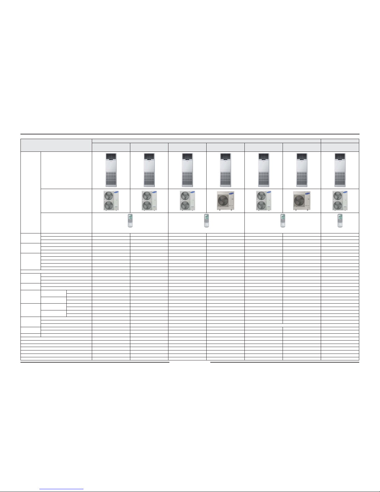
2-3-1 Filter
2-3-2 Accessory
2-3 Accessory and Option Specifications
Item Descriptions Code-No. Remark
Air Filter DB63-02928B
Basic/
Water Washing
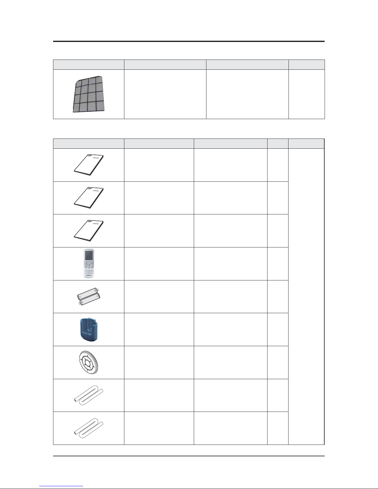
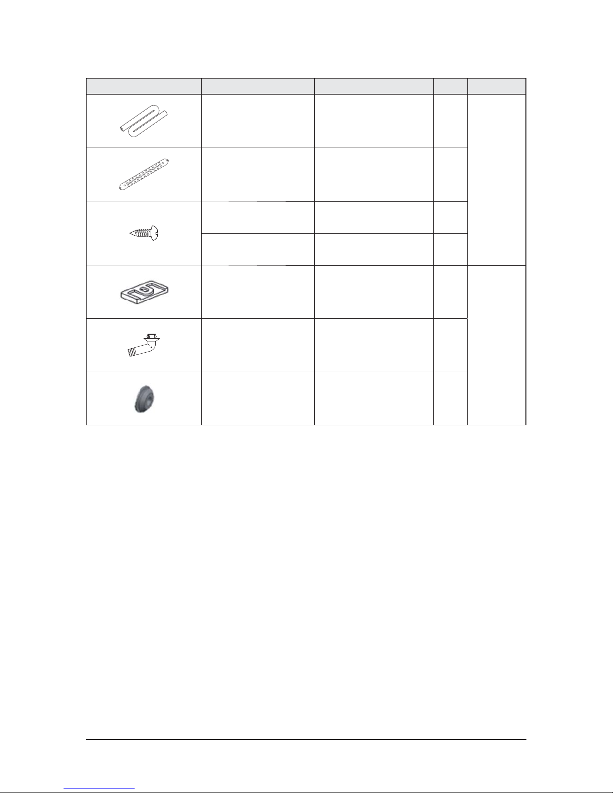
Item Descriptions Code-No. Q'ty Remark
Manual
(AC048/036KNPPCC)
DB68-04872A 1
Indoor Unit
Manual
(AC140/100KNPDEH)
DB68-06271A
DB68-06272A
1
Manual
(AC048/036KNPDEC)
DB68-06270A 1
Wireless Remocon DB93-15883B 1
Battery DB47-90024A 2
Holder Remocon DB61-06087A 1
Rubber Cabi Hole DB73-00195A 1
Insulation Tube DB62-10944A 1
Insulation
(AC048/036KN*)
DB72-50300A 1
Product Specifications
Samsung Electronics 2-6
Item Descriptions Code-No. Q'ty Remark
Insulation
(AC140/100KN*)
DB72-50300C 1
Indoor Unit
Holder Top DB61-40042B 1
Screw (L14) 6002-000538 4
Screw (L12) 6002-000231 4
Rubber leg DB73-20134A 4
Outdoor Unit
Drain Plug DB67-00806A 1
CAP Drain DB63-10355C 3
Samsung Electronics 3-1
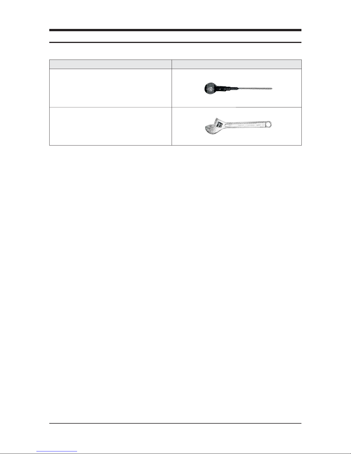
Item Remark
+Screw driver
Monkey spanner
QNecessary Tools
3. Disassembly and Reassembly
3-2 Samsung Electronics
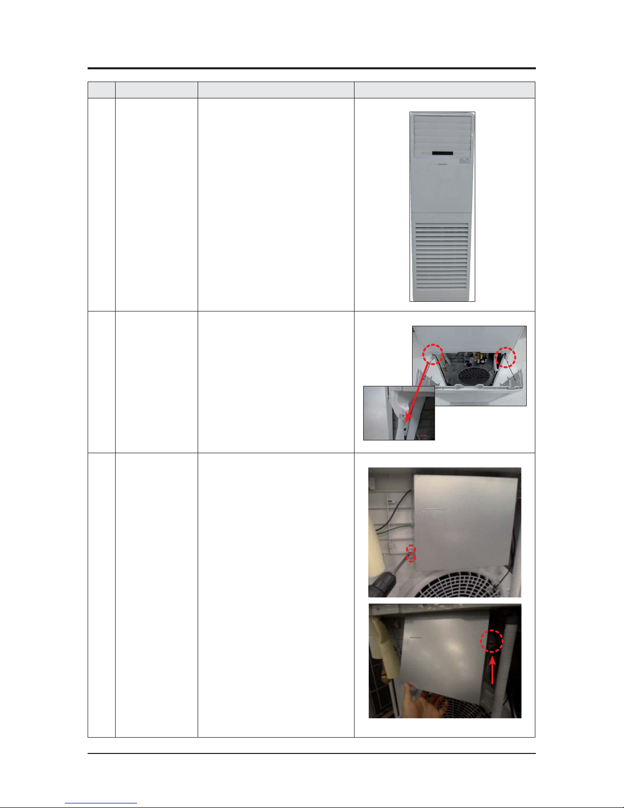
No Parts Procedure Remark
1 Indoor unit 1) Stop the operation of the air conditioner
and disconnect the main power supply.
2 Ass'y Inlet Part 1) Open the Ass'y Inlet and remove the
safety clips.
3 Ass'y Cover Control 1) Loosen one fixing screw of Ass'y Cover
Control. (Use +Screw driver) and detach
the cover.
2) Lift up the Ass'y Cover Control and detach
it by pulling the bottom outward.
3-1 Indoor Unit
Disassembly and Reassembly
Samsung Electronics 3-3
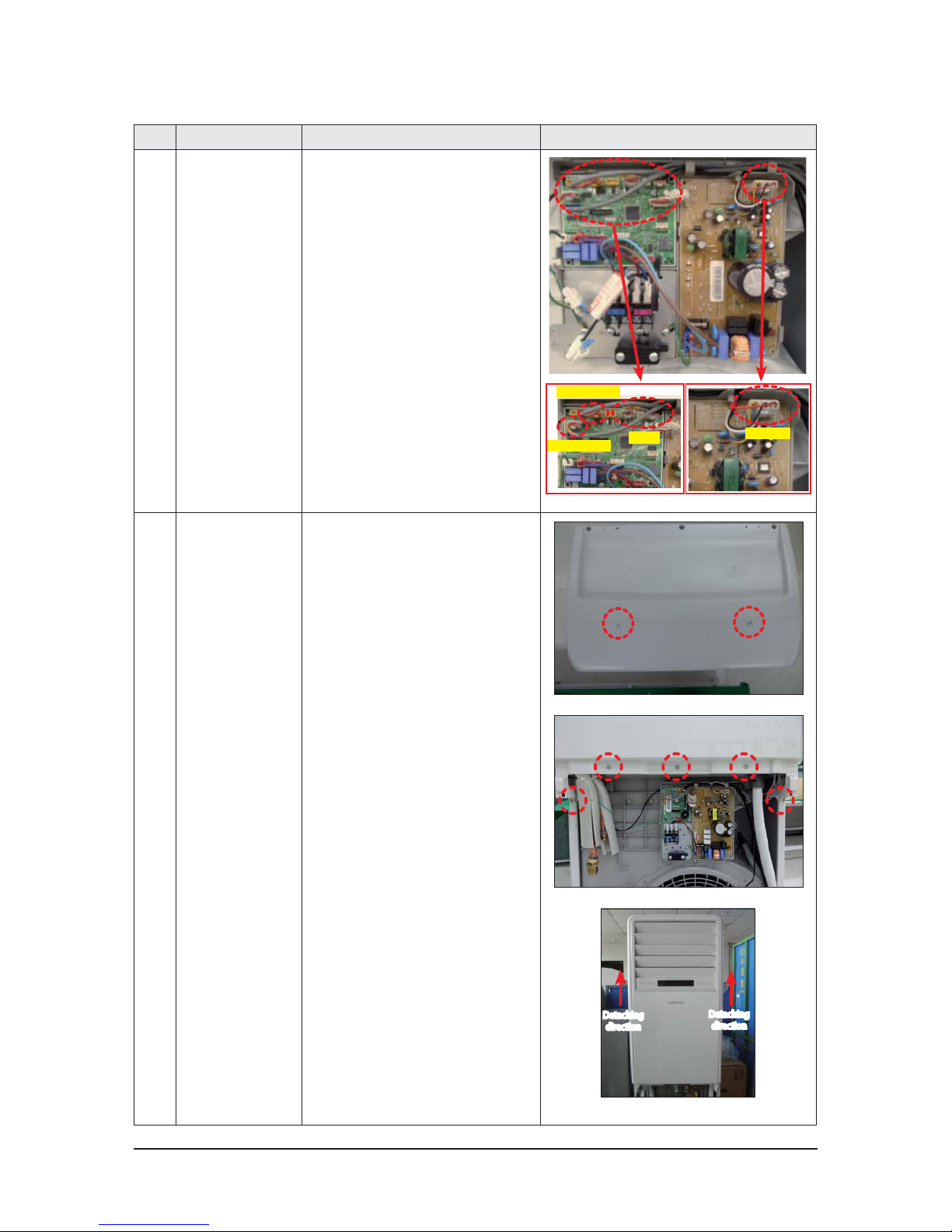
No Parts Procedure Remark
3) Detach the connectors connected to
Panel-Outlet and the Motor Connector.
Motor-In
Panel
Horizontal blade
Vertical blade
4 Ass'y Panel-outlet 1) Loosen the 7 fixing screws of
Ass'y Panel-Outlet and detach the
panel outlet by pushing upwards.
(Use +Screw driver)
Detaching
direction
Detaching
direction
Disassembly and Reassembly
3-4 Samsung Electronics
No Parts Procedure Remark
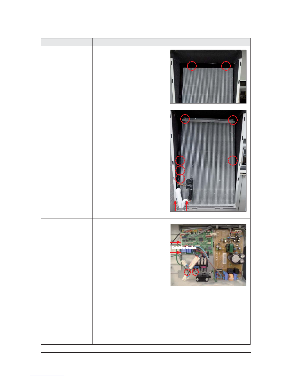
5 Ass’y Eva 1) Loosen the 2 fixing screws of Cover EVA
Top and detach the Top.
2) Loosen the 4 fixing screws of EVA.
3) Loosen the grounding screw.
4) Pull out the sensor cable.
5) Pull out the Bracket Pipe upward.
6) Pull the upper part of the Heat
Exchanger toward you and lift up the
Heat Exchanger to detach.
6 Ass'y Control In 1) Loosen the 1 fixing screw of Ass'y
Control.
2) Loosen the EVA grounding fixing screw.
3) Detach the Ass'y Control In by pushing
it to the right.
Detaching direction
❷
❶
Disassembly and Reassembly
Samsung Electronics 3-5
No Parts Procedure Remark
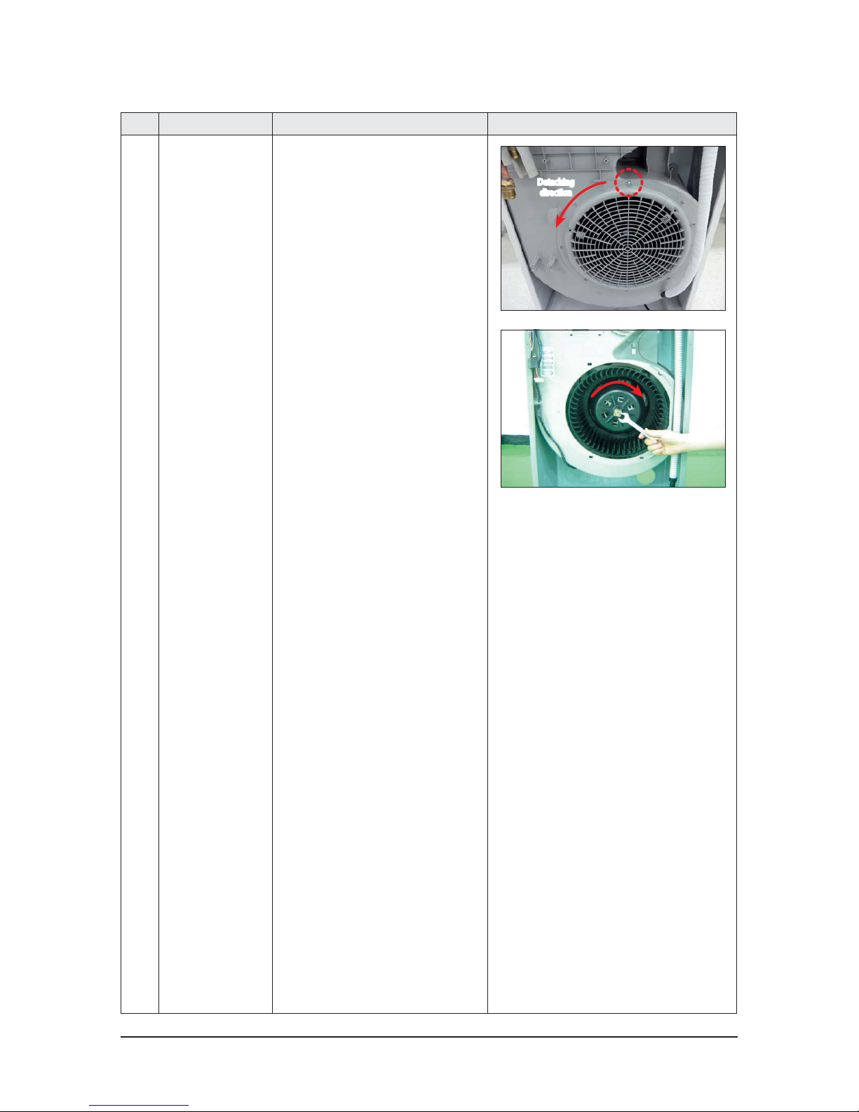
7 Ass’y Blower 1) Loosen the 1 fixing screw of Guard Fan.
(Use +Screw driver)
2) Push the Guard Fan in the arrow
direction and detach the guard.
3) Loosen the Blower nut clockwise and
pull the Blower toward you and detach
it. (Use a monkey spanner.)
Detaching
direction
Disassembly and Reassembly
3-6 Samsung Electronics
No Parts Procedure Remark
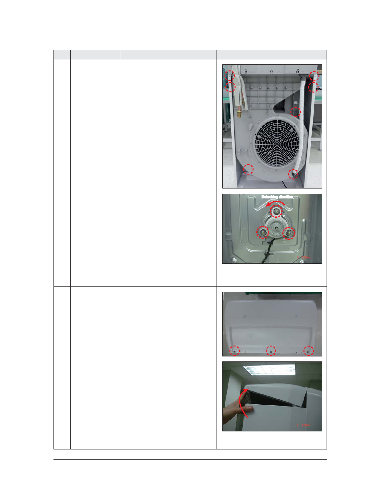
8 Ass’y Motor Blower 1) Loosen the 5 fixing screws of
Ass'y Duct Case and detach the case.
(Use +Screw driver)
2) Loosen the 3 fixing screws of
Motor and ground fixing screw.
(Use a monkey spanner.)
(Remove the connectors before
detaching the Motor.)
9 Cover Top 1) Loosen the 3 fixing screws of
Cover-Top and detach the cover.
(Use +Screw driver),
(Screw : TH type2 M4, L10, BLK)
2) Lift up the rear of Cover Top and
detach it.
Detaching direction
Disassembly and Reassembly
Samsung Electronics 3-7
No Parts Procedure Remark
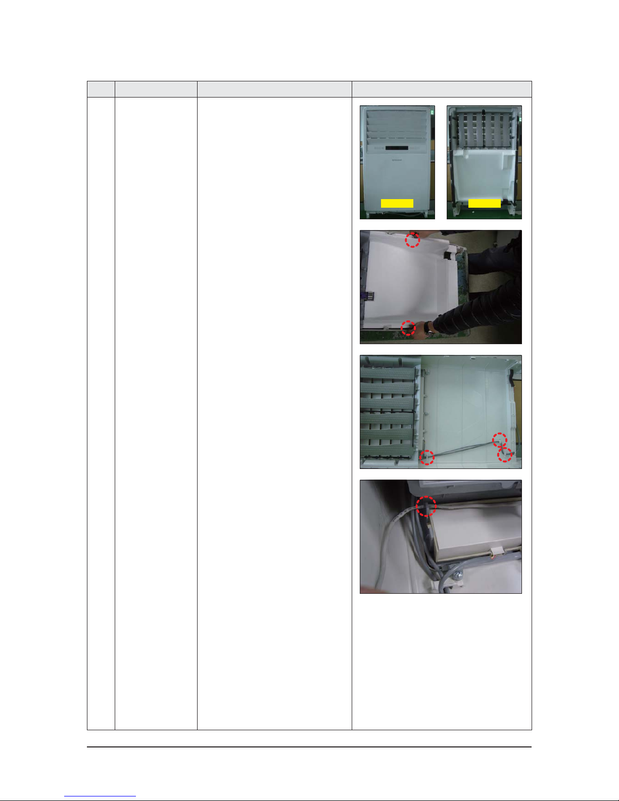
10 Ass'y Panel-Outlet
1) Panel-Outlet
2) As you push the 2 hooks on each side of
Panel outward, detach the bottom part
of Partition by lifting it toward you.
3) Detach the wire positioned with
Holder Wire.
4) Detach the wire positioned with
Holder Wire.
Rear sideFront side
Disassembly and Reassembly
3-8 Samsung Electronics
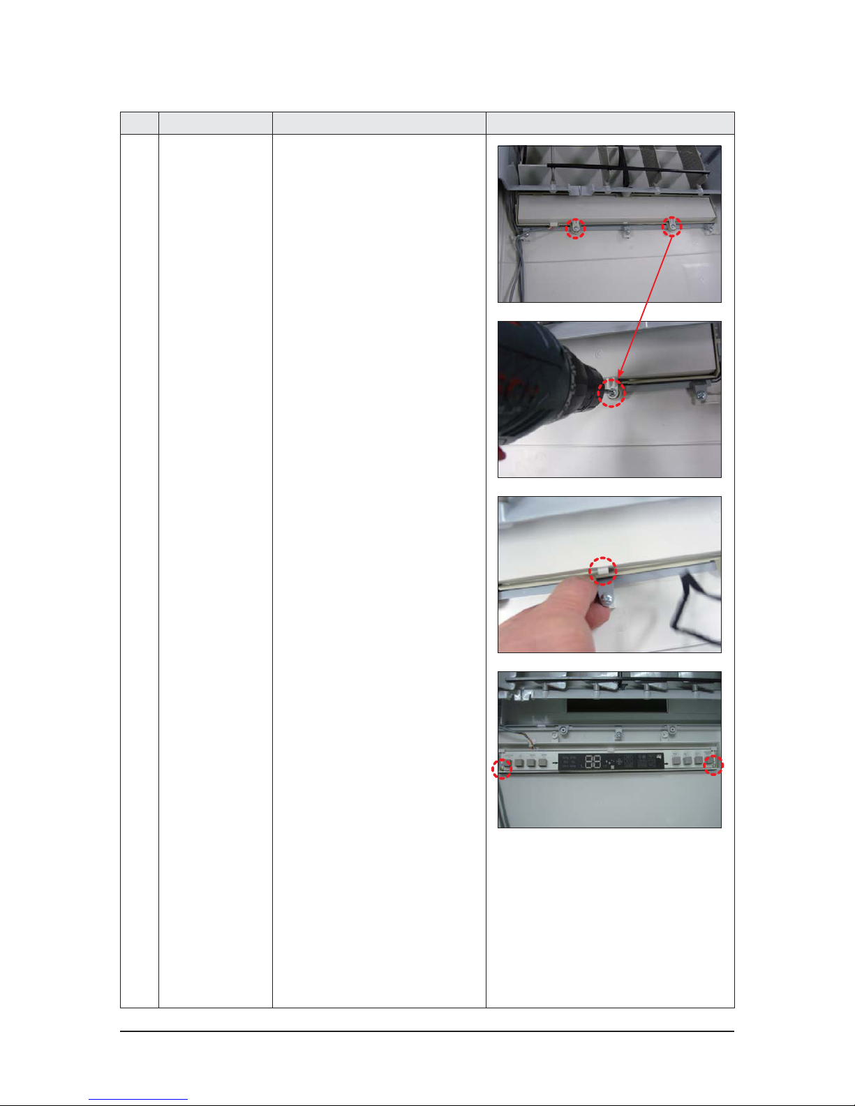
No Parts Procedure Remark
11 Ass'y Panel-outlet
- Seperate Display PBA
1) Loosen the 2 fixing screws of Case
Display PBA and detach the case.
(Use +Screw driver)
2) Unlink the fixing hook placed in the
middle of Case Display PBA.
3) Loosen the 2 fixing screws of PBA and
detach the PBA. (Use +Screw driver)
Disassembly and Reassembly
Samsung Electronics 3-9
No Parts Procedure Remark
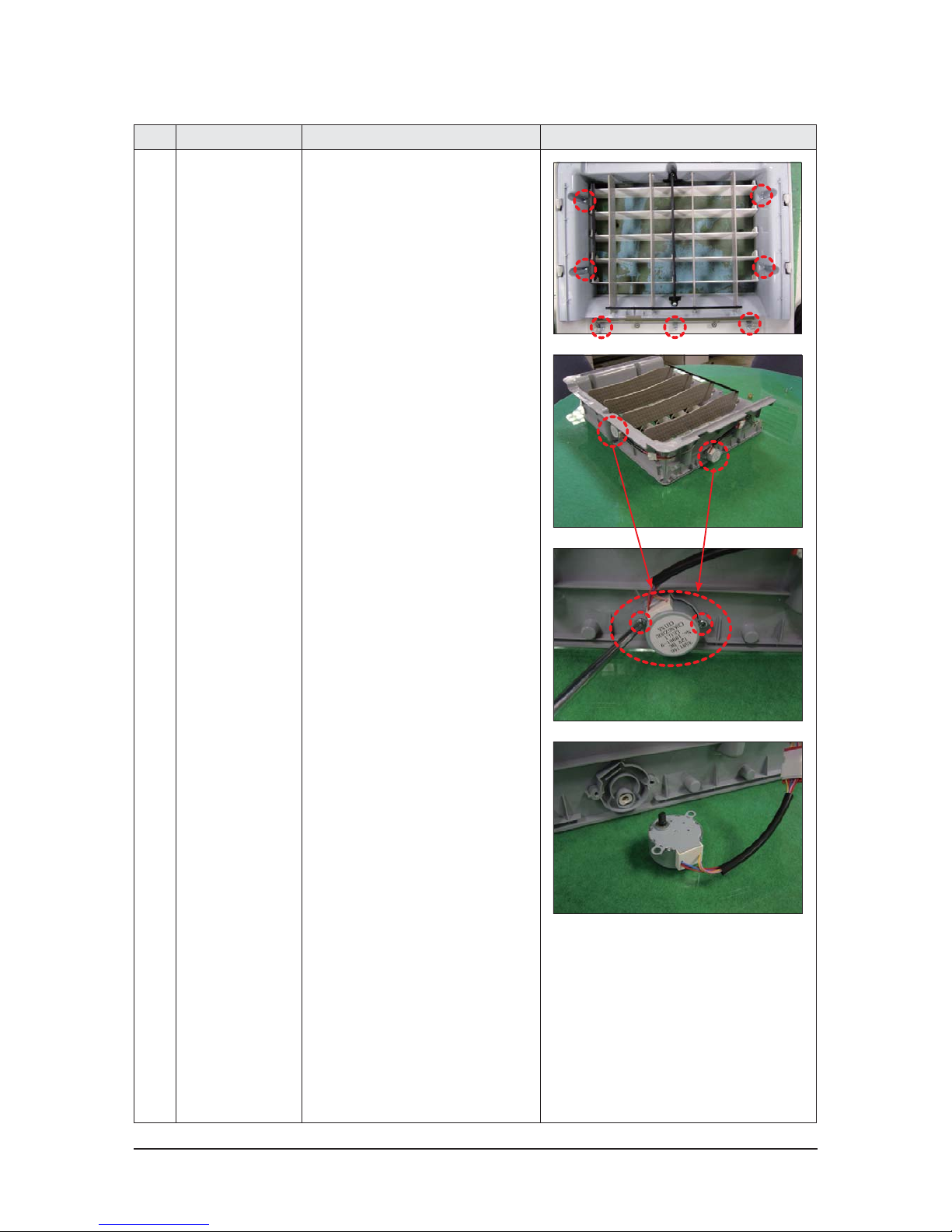
12 Ass'y Panel-outlet
- Motor Step
1) Loosen the 8 fixing screws of
Holder Blade and detach the holder.
(Use +Screw driver)
2) Loosen the 2 fixing screws of
Step Motor and detach the motor.
(Use +Screw driver)
3) The detached Step Motor.
3-10 Samsung Electronics
3-2 Outdoor Unit
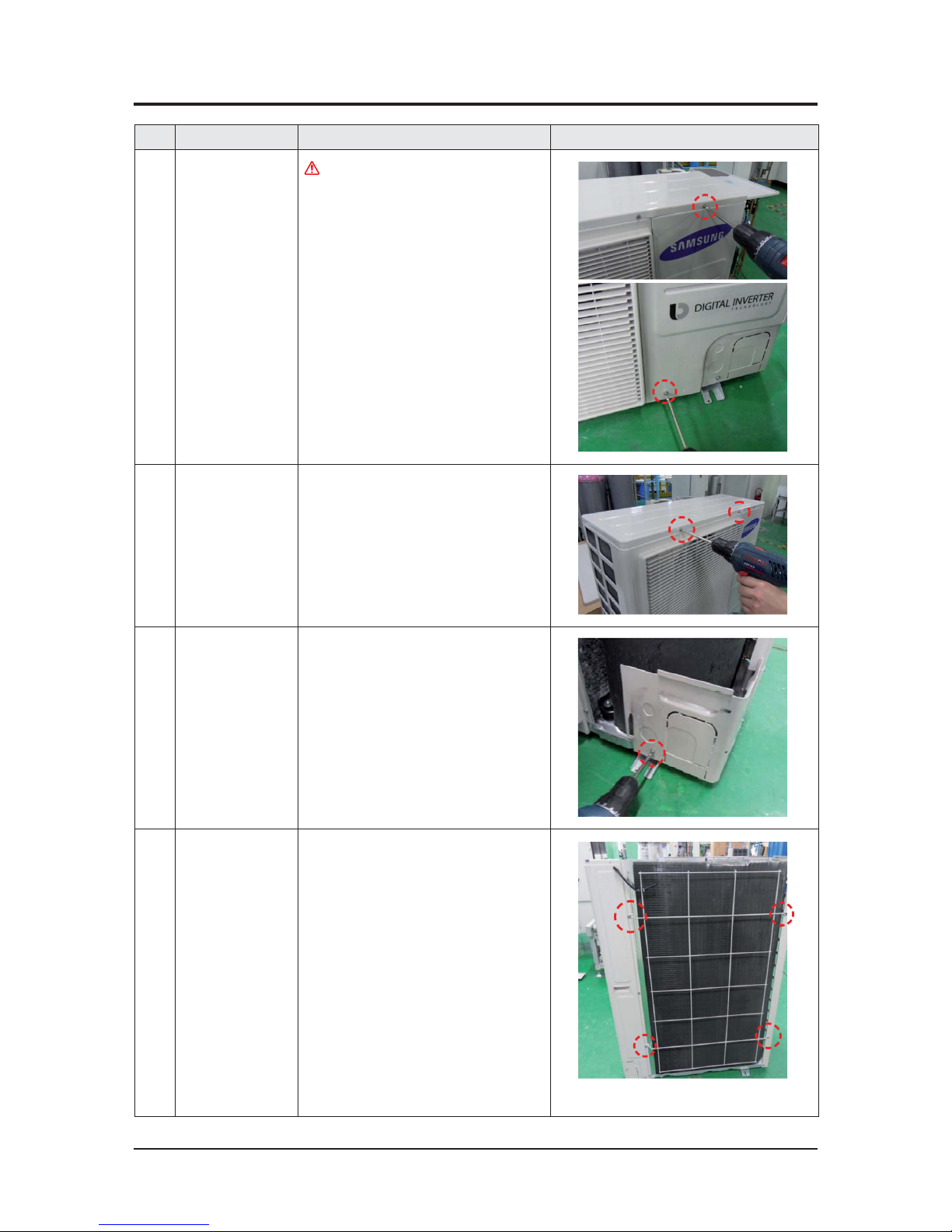
No Parts Procedure Remark
1 Cabi Front RH
You must turn off the Power before
disassembly.
1) Unscrew and remove two mounting
screw in the Cabinet Front RH.
(Use +Screw Driver)
2 Cabi Top
1) Unscrew and remove 9 screws
on each side of the Cabinet-Top.
(Use +Screw Driver)
3 Cabi Install Front
1) Unscrew and remove 1 screw
in the Cabinet-Install Front.
(Use +Screw Driver)
4 Guard Cond
1) Pull the sensor from Guard Cond.
2) Unscrew and remove 4 screws
in the Guard Cond.
(Use +Screw Driver)
Disassembly and Reassembly
Samsung Electronics 3-11
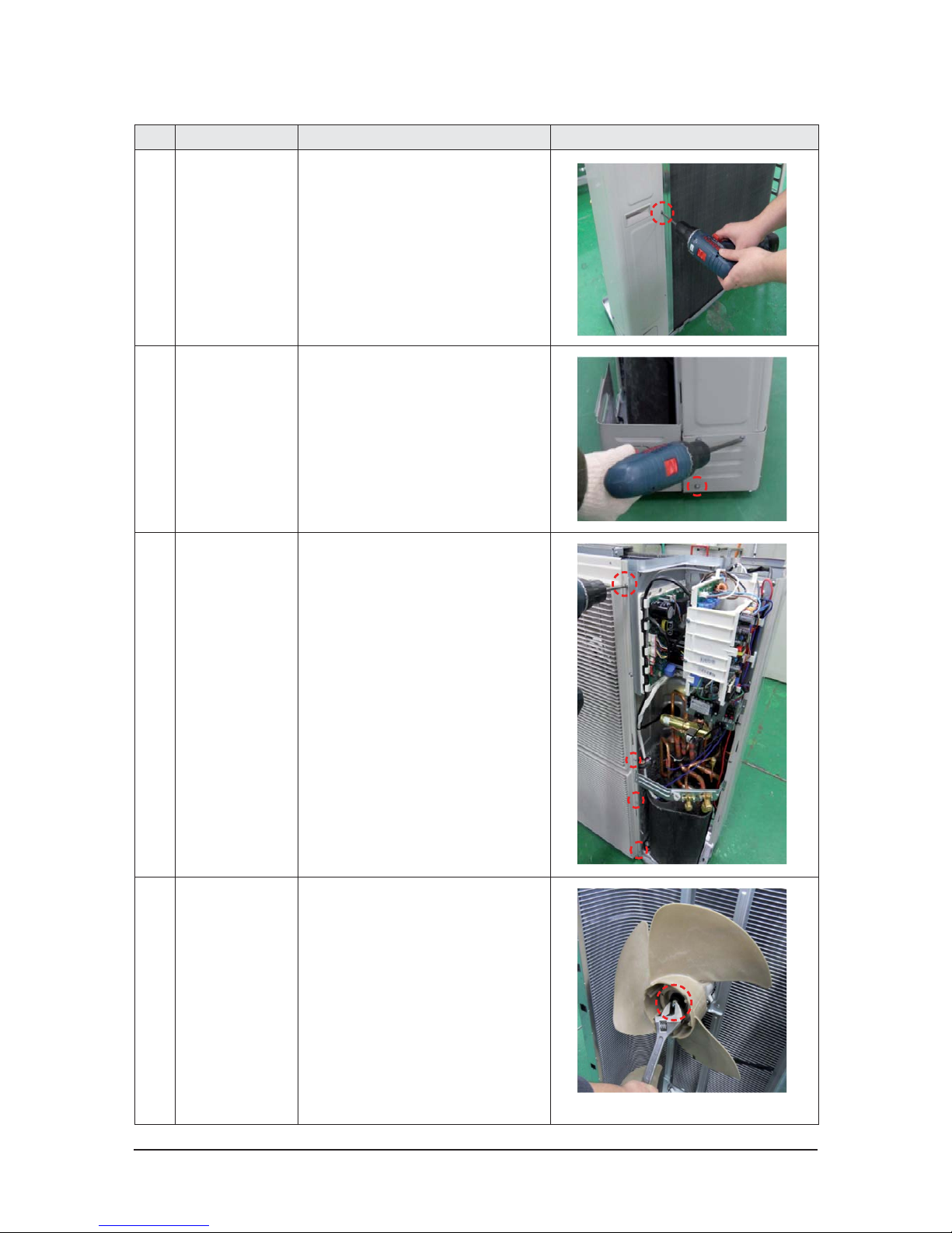
No Parts Procedure Remark
5 Cabi Back RH
1) Pull the sensor from Cabi Back RH.
2) Unscrew and remove 4 screws
on each side of the Cabinet Back RH.
(Use +Screw Driver)
6 Cabi Install Back
1) Unscrew and remove 1 screw
in the Cabinet-Install Back.
(Use +Screw Driver)
7 Cabi Front LF
1) Unscrew and remove 10 screws
in the Cabinet-Front LF.
(Use +Screw Driver)
8 Fan
1) Turn 2 mounting nuts as shown in
the picture and remove it.
(Use Adjustable Wrench)
 Loading...