

Samsung AC024MNADCH/AA, AC018JXADCH/AA, AC018MNADCH/AA, AC012KXADCH/AA, AC024JXADCH/AA Service Manual
...
Refer to the service manual in the GSPN(see the rear cover) for the more information.
AIR CONDITIONER CONTENTS
SYSTEM AIR CONDITIONER
1. Precautions
2. Product Specifications
3. Disassembly and Reassembly
4. Troubleshooting
5. PCB Diagram
6. Wiring Diagram
7. Reference Sheet
AC012/018/024MNADCH
INDOOR UNIT OUTDOOR UNIT
Model :
AC012MNADCH/AA
AC018MNADCH/AA
AC024MNADCH/AA
AC030MNTDCH/AA
AC036MNTDCH/AA
AC012KXADCH/AA
AC018JXADCH/AA
AC024JXADCH/AA
AC030JXADCH/AA
AC036JXADCH/AA
AC012KXADCH
AC024JXADCH
AC030JXADCH
AC018JXADCH
AC036JXADCH
AC030/036MNTDCH

2 Samsung Electronics
Contents
11. Precautions
........................................................................................................................................
1-1
1-1 Precautions for the Service
..............................................................................................................
1-1
1-2 Precautions related to static electricity and PL
............................................................................
1-1
1-3 Precautions related to product safety
...........................................................................................
1-2
1-4 Other precautions
..............................................................................................................................
1-2
12. Product Specifications
...............................................................................................................
2-1
2-1 The Feature of Product
.....................................................................................................................
2-1
2-2 Product Specifications
......................................................................................................................
2-2
2-3 Accessories
..........................................................................................................................................
2-5
13. Disassembly and Reassembly
...............................................................................................
3-1
3-1 Indoor Unit
.........................................................................................................................................
3-2
3-2 Outdoor Unit
.....................................................................................................................................
3-18
14. Troubleshooting
............................................................................................................................
4-1
4-1 Troubleshooting for indoor unit
..................................................................................................
4-1
4-2 Troubleshooting for outdoor unit
.................................................................................................
4-11
4-3 Troubleshooting by symptoms
.....................................................................................................
4-13
4-3-1 Indoor temperature sensor (open/short)
..........................................................................
4-13
4-3-2 Indoor heat exchanger temperature sensor (open/short)
.............................................
4-14
4-3-3 Indoor FAN error
.....................................................................................................................
4-15
4-3-4 Communication error after finishing Tracking
.................................................................
4-16
4-3-5 Indoor unit float sensor error
...............................................................................................
4-17
4-3-6 EEPROM circuit failure
...........................................................................................................
4-18
4-3-7 Outdoor unit is not powered on
.........................................................................................
4-19
4-4 Troubleshooting by symptoms
................................................................................................................... 4-21
4-4-1 Communication error
..........................................................................................................
4-21
4-4-2 Outdoor temperature sensor error
....................................................................................
4-22
4-4-3 Outdoor Coil temperature sensor error
............................................................................
4-24
4-4-4 Outdoor Discharge temperature sensor error
.................................................................
4-26
4-4-5 Outdoor Discharge over temperature error
.....................................................................
4-28
4-4-6 Outdoor Fan motor error
.................................................................................................................... 4-29
4-4-7 Compressor starting error .................................................................................................................. 4-30
4-4-8 Compressor wire missing error/rotation error .......................................................................... 4-31
4-4-9 O.C(Over Current) error ....................................................................................................................... 4-32
4-4-10 DC_link voltage sensor error .......................................................................................................... 4-33
4-4-11 DC_link voltage under/over error, Over voltage protection error/PFC over load ..... 4-34

Samsung Electronics 3
4-4-12 DC_link voltage sensor error ........................................................................................................... 4-35
4-4-13 Current sensor error/Input current sensor error .................................................................... 4-36
4-4-14 Heatsink sensor error/Heatsink over heat ................................................................................. 4-37
4-4-15 Comp Vlimit error/Comp current limit error ............................................................................ 4-38
4-4-16 EEPROM error/OTP error .................................................................................................................. 4-39
4-4-17 AC zero cross signal error ................................................................................................................. 4-40
4-4-18 Operation condition secession error............................................................................................ 4-41
4-4-19 Capacity miss match error ............................................................................................................... 4-42
4-4-20 Gas leak error ........................................................................................................................................ 4-43
15. PCB Diagram
.....................................................................................................................................
5-1
5-1 Indoor Unit
.........................................................................................................................................
5-1
5-2 Outdoor Unit
.....................................................................................................................................
5-4
16. Wiring Diagram
..............................................................................................................................
6-1
6-1 Indoor Unit
........................................................................................................................................
6-1
6-2 Outdoor Unit
....................................................................................................................................
6-2
7. Reference Sheet
.............................................................................................................................
7-1
7-1 Index for Model Name
......................................................................................................................
7-1
7-2 Refrigerating Cycle Diagram
............................................................................................................
7-2

Samsung Electronics 1-1
1. Precautions
1-1 Precautions for the Service
XUse the standard parts when replacing the electric parts.
– Confirm the model name, rated voltage, rated current of the electric parts.
XWhen repairing the equipment, connection of the harness parts must be firm and solid.
– A loose connection may cause noise or other malfunction.
XWhen assembling and disassembling the equipment while it is laid down, lay it on soft cloth.
– Otherwise it may scratch the back of the exterior of the product.
XRemove dust or dirt completely from the housing block, wiring block and service parts during repair.
– This helps prevent the danger of fire caused by tracking or short circuit.
XFasten the valve caps of service valves and charging valves of outdoor unit as much as possible using adjustable wrenches.
XCheck the status of the components’ assembly after repair service.
– The status must be the same as before the repair service.
1-2 Precautions related to static electricity and PL
X The PCB power supply block is susceptible to static electricity. Therefore, care must be taken during repair or measuring
while the power is on.
– Wear insulation gloves for PCB repair or measuring.
X Check whether the installation location is at least two meters away from other electronic products such as TV, video, or
audio.
– Otherwise, the video quality might be degraded or noise might be generated.
X Do not let end users repair the products themselves.
– Unauthorized disassembly might cause electric shock or fire.

1-2 Samsung Electronics
1-3 Precautions related to product safety
X Do not pull the power cord and do not touch the power plug or aux power switch with wet hands.
– It might cause electric shock or fire.
X A damaged power line or power plug must be replaced to prevent danger.
X Do not bend the power cable with excessive force, and do not place a heavy weight on the case as it might damage the
cable.
– It might cause electric shock or fire.
X Do not use multiple electric outlets.
– This might cause electric shock or fire.
X Connect the ground terminal when necessary.
– You must connect the ground terminal if you determine that there is a danger of electric leakage due to moisture or water.
X Unplug the power cable or turn off the auxiliary power switch for electric part replacement and repair service.
– Otherwise it might cause electric shock.
X Instruct end users to separate the batteries from the remote controllers and store them separately when the product is not
used for long time.
– Otherwise leakage from the dry cell may cause problems with the remote controller.
1-4 Other precautions
X The pipes should have no leaks during installation, and the compressor must be stopped before removing connecting
pipes for pump down work. Operating the compressor while the service valve is open and coolant pipe is not properly
connected may cause explosion or injury due to abnormal high pressure created inside the coolant cycle as the air can be
absorbed through the pipe.
X Pump Down work procedure (When uninstalling the product)
– Turn on the air conditioner, select cooling operation, and run the compressor for more than three minutes.
– Release the high pressure and low pressure valve caps.
– Close the high pressure valve completely using an L-wrench
– After about two minutes, close the low pressure valve completely.
– Stop running the air conditioner.
– Separate the connecting pipe.

Samsung Electronics 2-1
X Built-in Cassette Type
After installed, the air conditioner can be harmonized with a room interior.
X High Performance & Energy Saving
With the advanced BLDC inverter technology, it makes a room cool with highly energy saving and arises the efficiency of air conditioner.
XLong Ambient Operation(In Low Temperature)
It can arise the reliability and the capacity of the air conditioner, especially operated in low temperature.
X Eco-friendly Product(Lead-Free, ROHS, WEEE)
X Easy installation of ultra-lightweight indoor unit
2. Product Specifications
2-1 The Feature of Product
2-2 Samsung Electronics
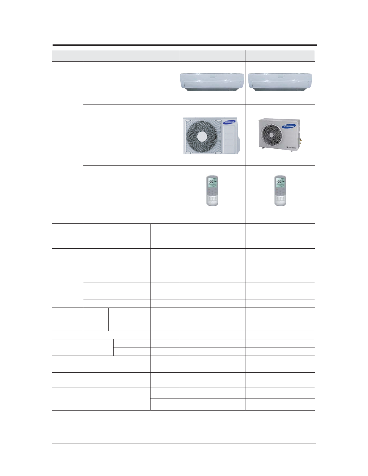
ITEM
AC012MNADCH
AC012KXA DCH
AC018MNAD CH
AC018JXAD CH
IMAGE
Indoor Unit
Outdoor Unit
Remote Controller
Power Product 1Φ, 220~240V, 50Hz 1Φ, 220~240V, 50Hz
Indoor L x H x D mm 750*246*249
896*261*261
Outdoor L x H x D mm 790*285*548 880*310*638
Indoor Product kg(Net) 7.6 10.6
Outdoor Product kg(Net) 36.2 45.0
Capacity
Cooling(STD) Btu/h 12 000
18 000
Heating(STD) Btu/h
14 000 20 000
Power
Consumption
Cooling(STD) W
122 0 216 0
Heating(STD) W
1680 1960
Operation
current
Cooling(STD) A
5.7 9.4
Heating(STD) A
7. 4 8 . 5
Noise
(Cooli ng/
Heating)
Indoor unit
In case of strongest air
blow
dBA
43/43 48/48
Outdoor unit
In case of strongest air
blow
dBA
54/54 58/58
Refrigerant (R410A) g 1050 1300
Connecting Pipe
Liquid mm 6.35
6.35
Gas mm
9.52 12.70
Additional Refrigerant (R410A) g/m
10 10
Standard m
7. 5 7. 5
Extension length(Total) m 20
30
Extension length(Elevation) m
15 15
Option Code
Product
Option
0100FC-19548C-272328-371708
0100 FC-19548 E-27343 E-3C170 D
Installation
Option
020000-100000-200000-300000
020000-100000-200000-300000
2-2 Product Specifications
Samsung Electronics 2-3
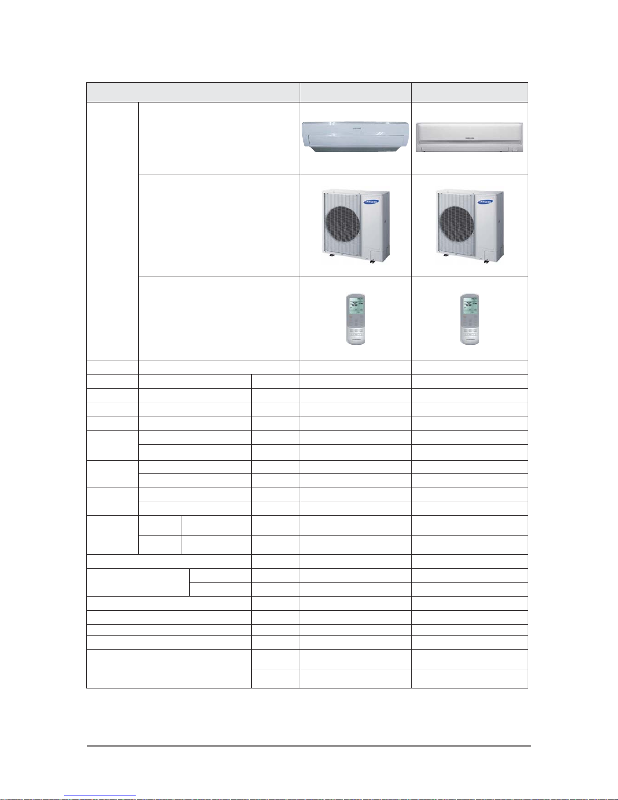
ITEM
AC024MNADCH
AC024JXADCH
AC030M NTDCH
AC030JX ADCH
IMAGE
Indoor Unit
Outdoor Unit
Remote Controller
Power Product 1Φ, 220~240V, 50Hz 1Φ, 220~240V, 50Hz
Indoor L x H x D mm
1065*294*301 1280*345*253
Outdoor L x H x D mm 940*330*998 940*330*998
Indoor Product kg(Net) 14.5 18.5
Outdoor Product kg(Net) 64.5 70.0
Capacity
Cooling(STD) Btu/h 24 000
30 000
Heating(STD) Btu/h
27 000 32 000
Power
Consumption
Cooling(STD) W
2350 3150
Heating(STD) W
2560 3360
Operation
current
Cooling(STD) A
10.4 13.7
Heating(STD) A
11. 4 14 . 7
Noise
(Cooli ng/
Heating)
Indoor unit
In case of strongest air
blow
dBA
51/51 55/55
Outdoor unit
In case of strongest air
blow
dBA
60/60 60/60
Refrigerant (R410A) g 2100 2600
Connecting Pipe
Liquid mm 6.35
9.52
Gas mm
15. 88 15. 88
Additional Refrigerant (R410A) g/m
10 22
Standard m
7. 5 7. 5
Extension length(Total) m 50
50
Extension length(Elevation) m
30 30
Option Code
Product
Option
0100 FC-19547 F-274750-37 17 0D
0110FC-193573-275A64-37770D
Installation
Option
020000-100000-200000-300000
020000-100000-200100-300000
2-4 Samsung Electronics
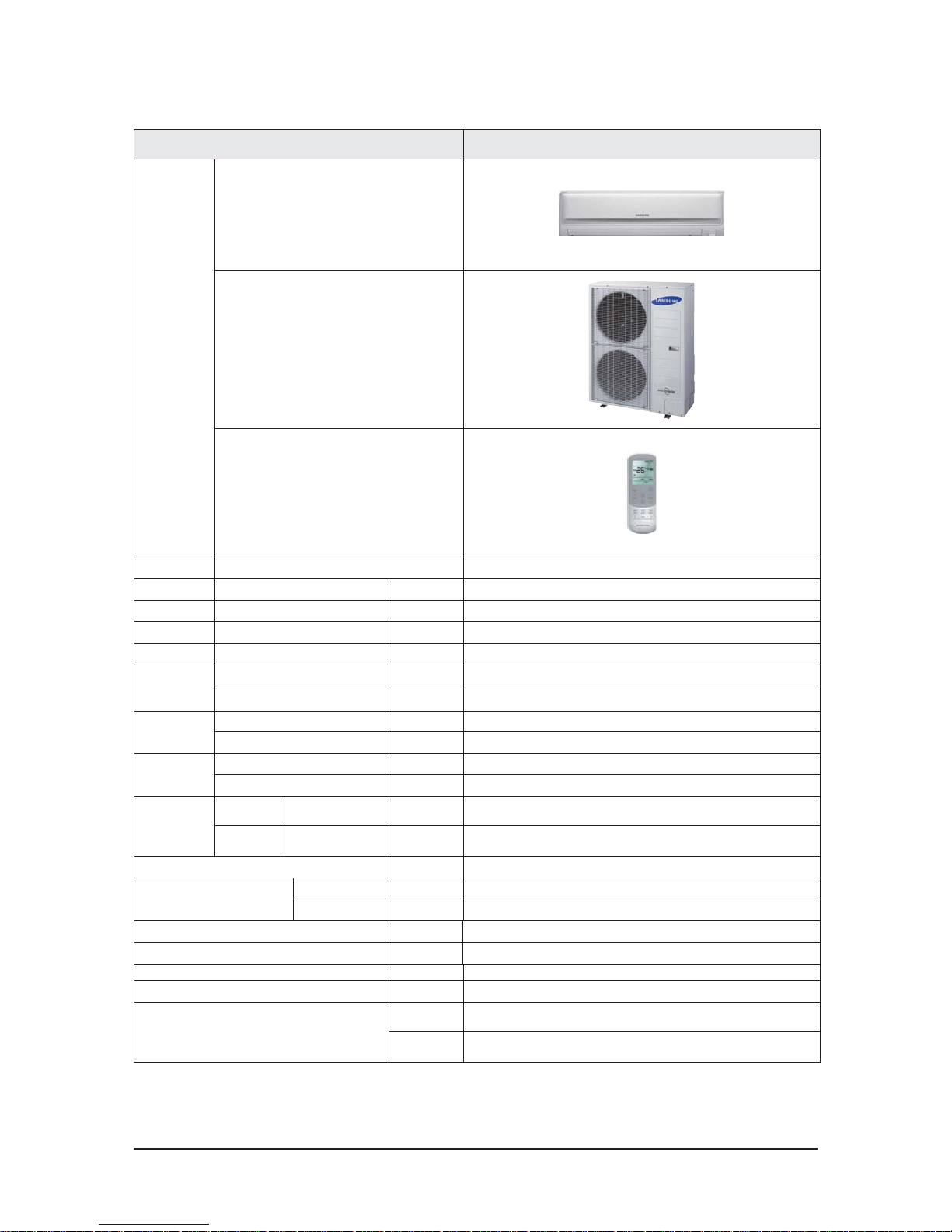
ITEM
AC036MNTDCH
AC036JX ADCH
IMAGE
Indoor Unit
Outdoor Unit
Remote Controller
Power Product 1Φ, 220~240V, 50Hz
Indoor L x H x D mm
128 0* 34 5*2 53
Outdoor L x H x D mm 940*330*1210
Indoor Product kg(Net) 18.5
Outdoor Product kg(Net) 88.0
Capacity
Cooling(STD) Btu/h
36 000
Heating(STD) Btu/h
40 000
Power
Consumption
Cooling(STD) W
3870
Heating(STD) W
4120
Operation
current
Cooling(STD) A
16. 5
Heating(STD) A
17.8
Noise
(Cooli ng/
Heating)
Indoor unit
In case of strongest air
blow
dBA
55/55
Outdoor unit
In case of strongest air
blow
dBA
60/60
Refrigerant (R410A) g 2800
Connecting Pipe
Liquid mm
9.52
Gas mm
15. 88
Additional Refrigerant (R410A) g/m
33
Standard m
7. 5
Extension length(Total) m
75
Extension length(Elevation) m
30
Option Code
Product
Option
0110FC-19459 4-276 470-39 670D
Installation
Option
020000-100000-200100-300000
Samsung Electronics 2-5
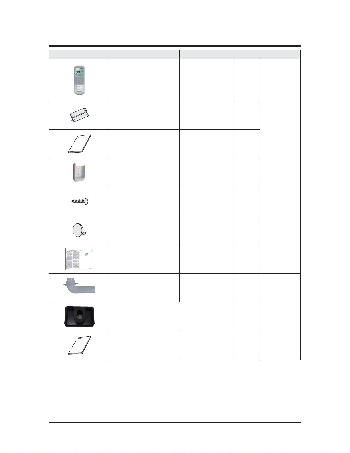
Item Description Code No. Q’ty Remark
Remote Control
DB93-15882S
1
Essential Offer
(Indoor Unit)
Batteries for Remote Control
4301-00 0121
2
USER &
INSTALLATION
MANUAL DB68-07119A
1
Remote Control Holder
DB61-06087A
1
M4 x 16 Tapped Screws
6002-000234
2
Cap Screws
DB67-01404B
(AC012/018/024MNADCH)
3
CARD WARRNATY DB68-02596B
1
Drain Plug
DB67-20011A
1
Essential Offer
(Outdoor Unit)
Rubber Leg DB67-01533A 4
INSTALLATION MANUAL DB68-06488A 1
2-3 Accessories
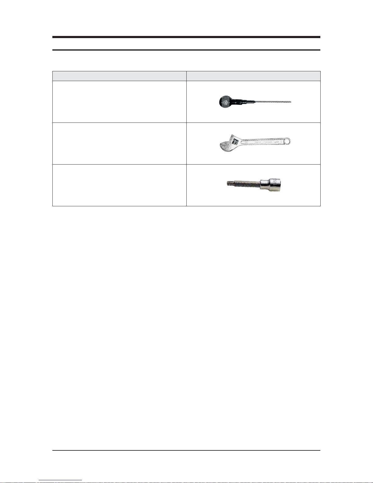
Samsung Electronics 3-1
Item Remarks
+SCREW DRIVER
Adjustable Wrench
(8mm, 10mm, 13mm)
M6, M8 Hex Wrench
XNecessary Tools
3. Disassembly and Reassembly
3-2 Samsung Electronics
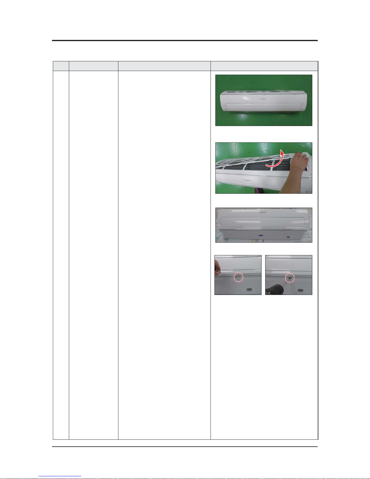
3-1 Indoor unit
XAC012MNADCH / AC018MNADCH / AC024MNADCH
No Parts
Procedure Remark
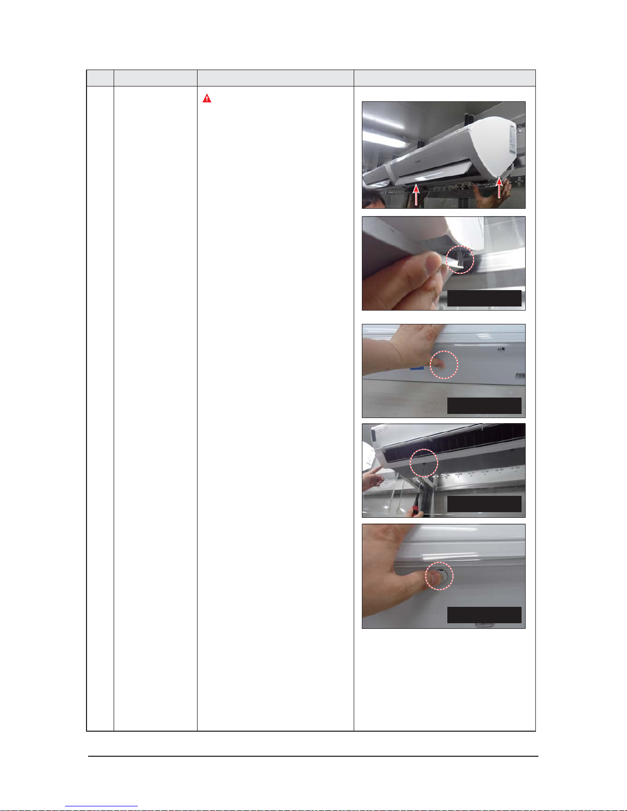
1 PANEL-FRONT 1) Stop the driving of air conditioner and shut off
main power supply.
2) Detach FILTER PRE from the PANEL FRONT.
3) Cover Panel is assembled on bottom of indoor
unit as shown in the figure.
Remove the Cap Screw as shown on the right
side and then remove the screw and separate
the Cover Panel.
Samsung Electronics 3-3
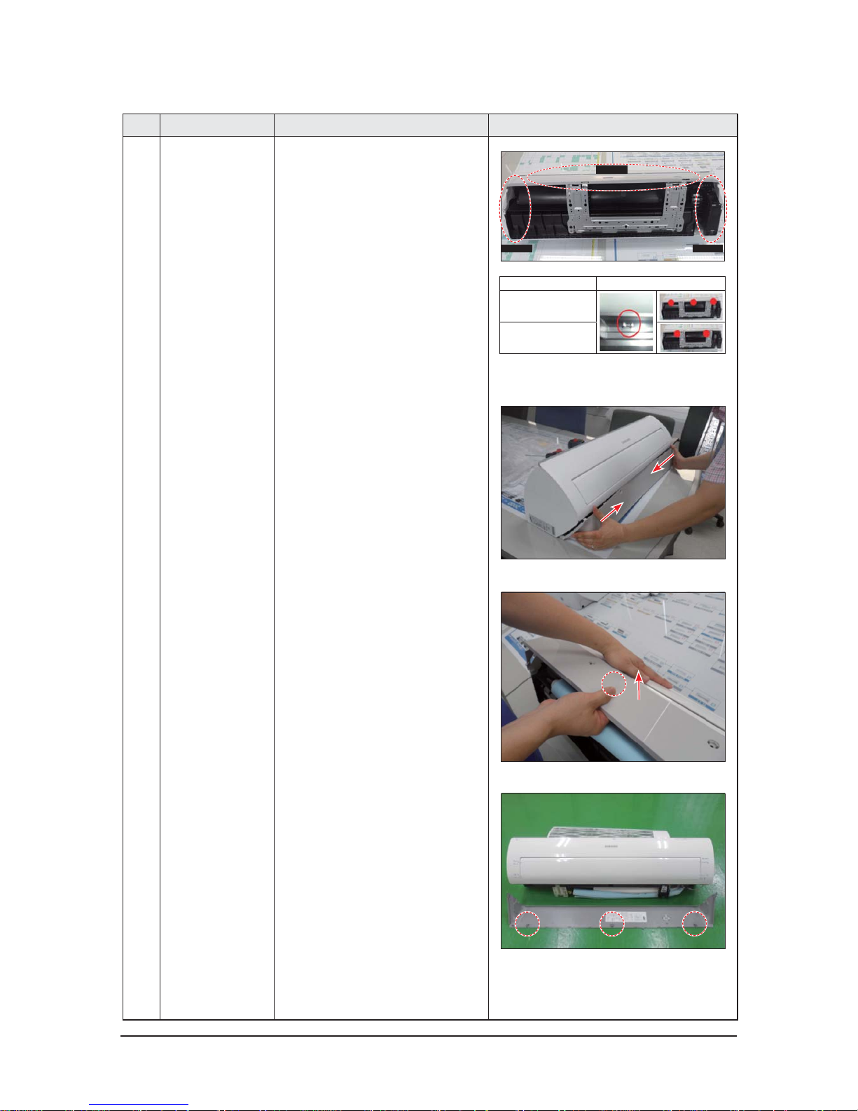
No Parts
Procedure Remark
4) Cover Panel is fixed to body by Hook in center area and
side area.
5) Separate the hook after pushing both end of Cover
Panel as shown in the figure.
(Watch out for the damage of the hook)
6) Raise front part upward obliquely as shown in the
figure and then remove the hooks.
Center area
Side area
Side area
HOOK
026/035
052/071
3-4 Samsung Electronics
No Parts
Procedure Remark
Caution:
Assembly of Cover Panel after service end.
-
Reassembly is in the reverse order of the
removal.
- Piping and drain hose must be careful not to
damage and Progress must be done with both
hands.
Hook (Side)
Hook (Center)
Screw
Cap Screw
Samsung Electronics 3-5
No Parts
Procedure Remark
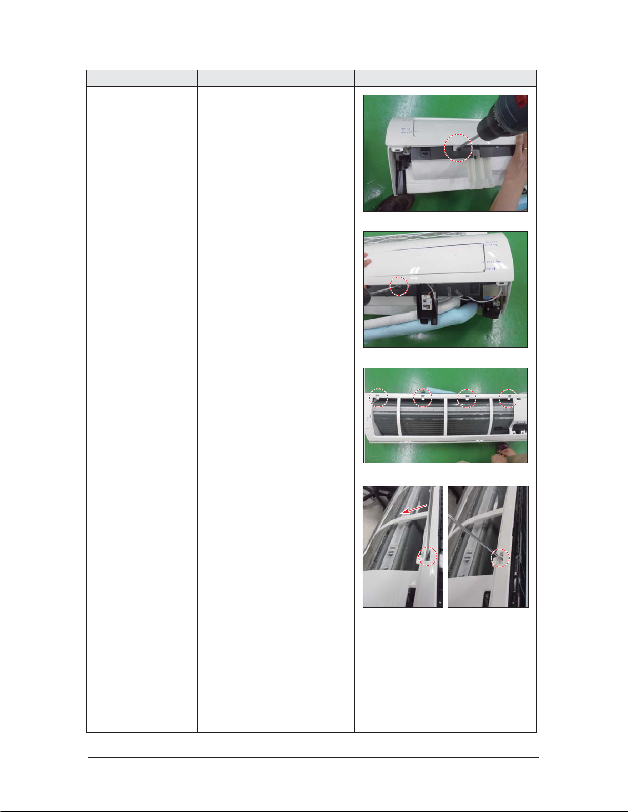
7) To detach the PANEL-FRONT from the main
frame, unfasten 2 screws at the bottom.
(use + Screw Driver)
8) To detach the COVER-PANEL from the main
frame, loosen 4 HOOK Structures.
When separate the hook :
Use the (-) screw Driver.
(-)Screw Driver Insert the hook and then pull the
hook as shown on the right side.
(Watch out for the damage of the hook)
3-6 Samsung Electronics
No Parts
Procedure Remark
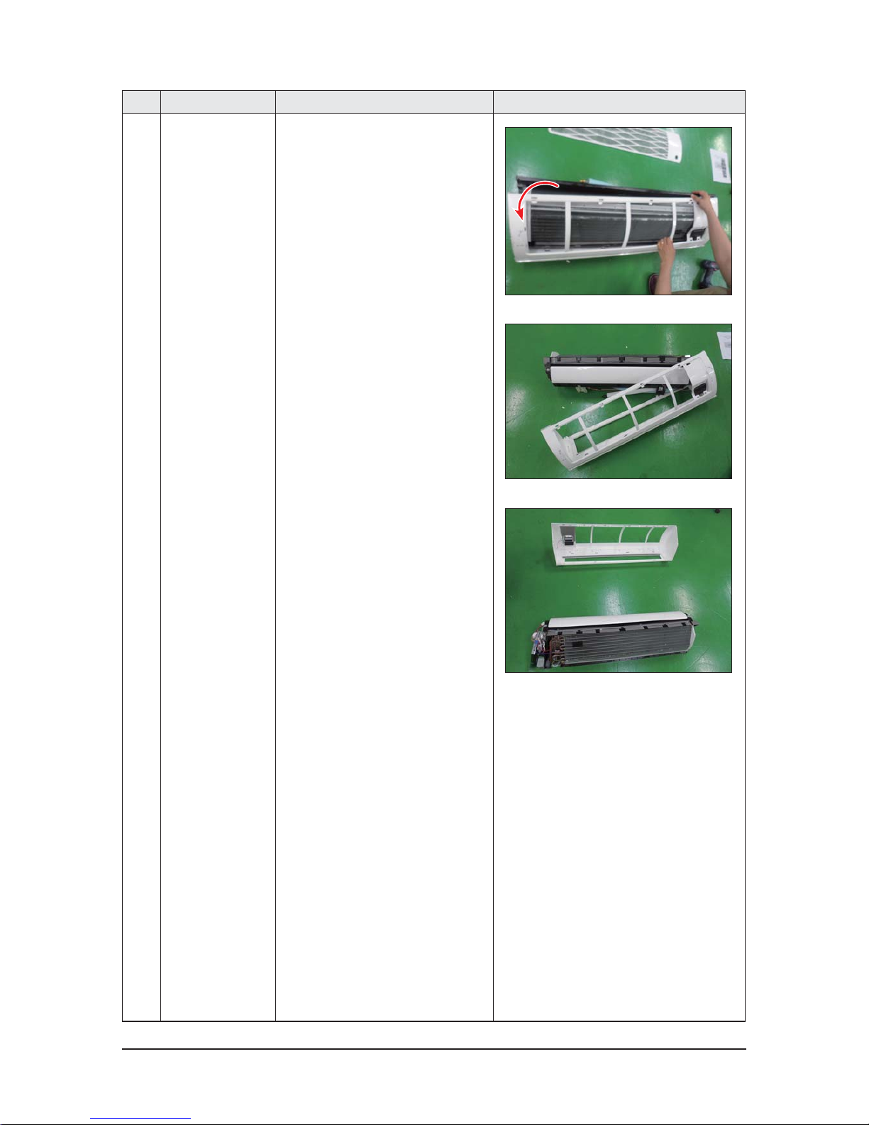
9) Remove the Panel Frame from the Main
Frame as shown on the right side.
Samsung Electronics 3-7
No Parts
Procedure Remark
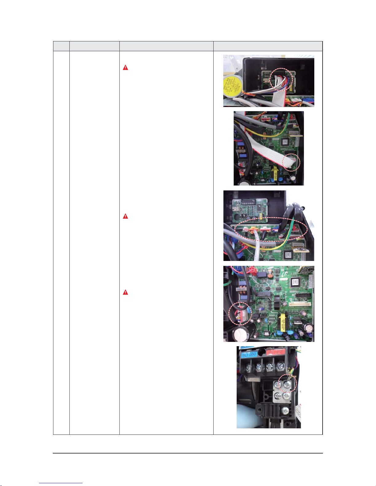
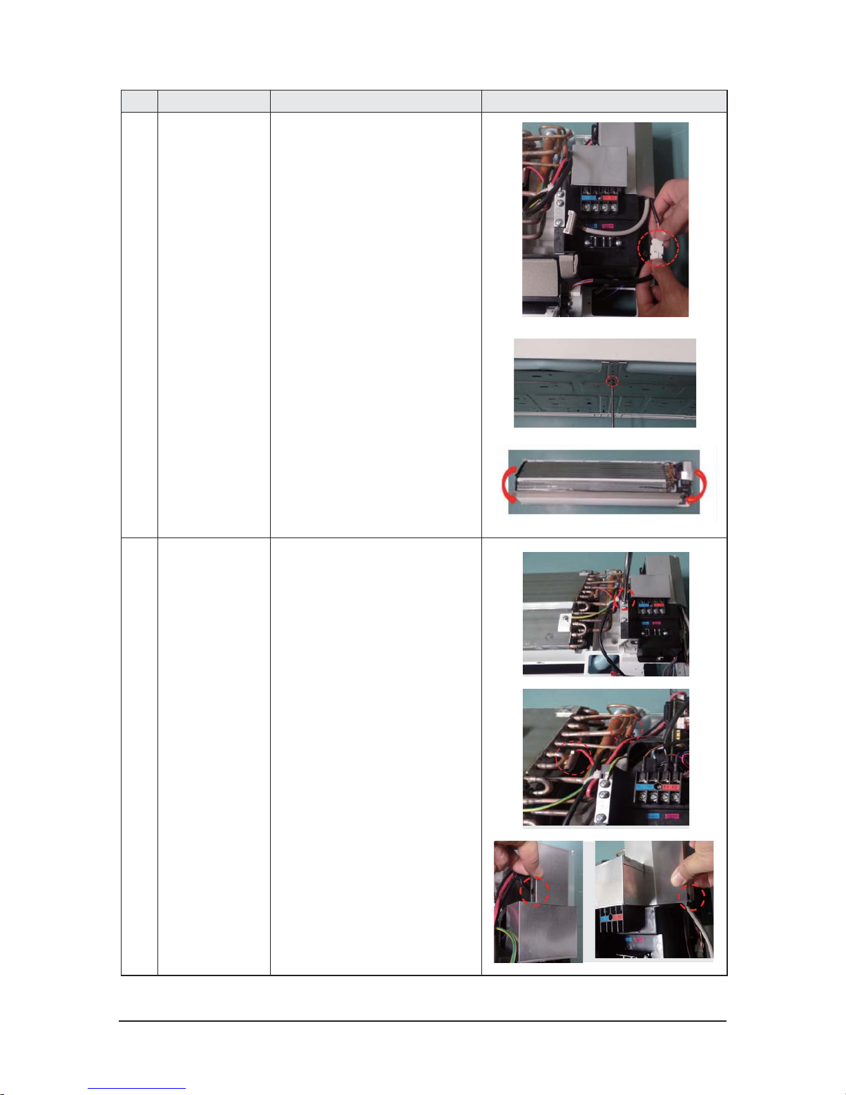
2
CONTORL IN
1) Lossen Sub PBA Wire.
Caution:
When you separate the connector,
pull pressing the locking button.
2) Lossen Stepping Motor, EEV, Display,
Sensor, SPI, Fuse Wire.
Caution:
When you separate the connector,
pull pressing the locking button.
3) Lossen Motor, Terminal Wire.
Caution:
When you separate the connector,
pull pressing the locking button.
4) Loosen Earth Wire.
3-8 Samsung Electronics
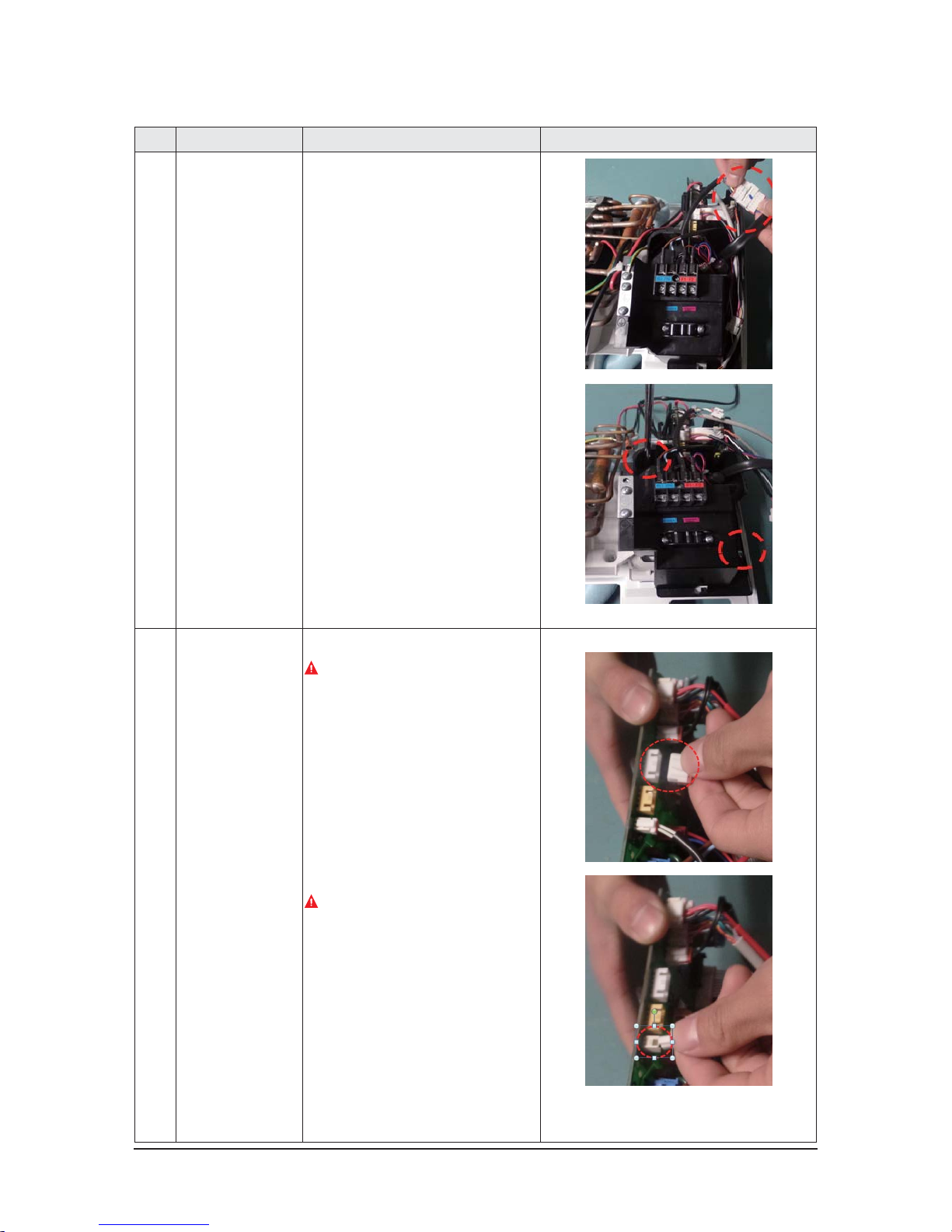
No Parts
Procedure Remark
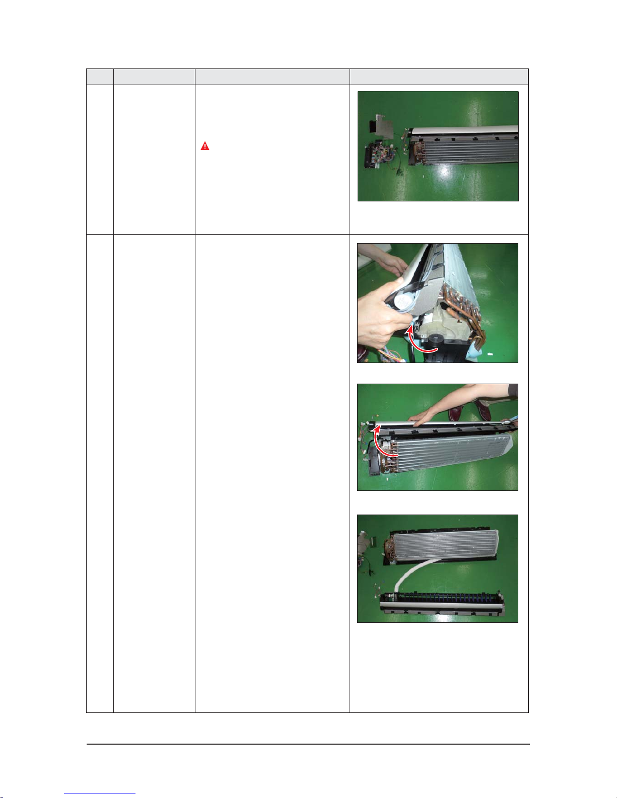
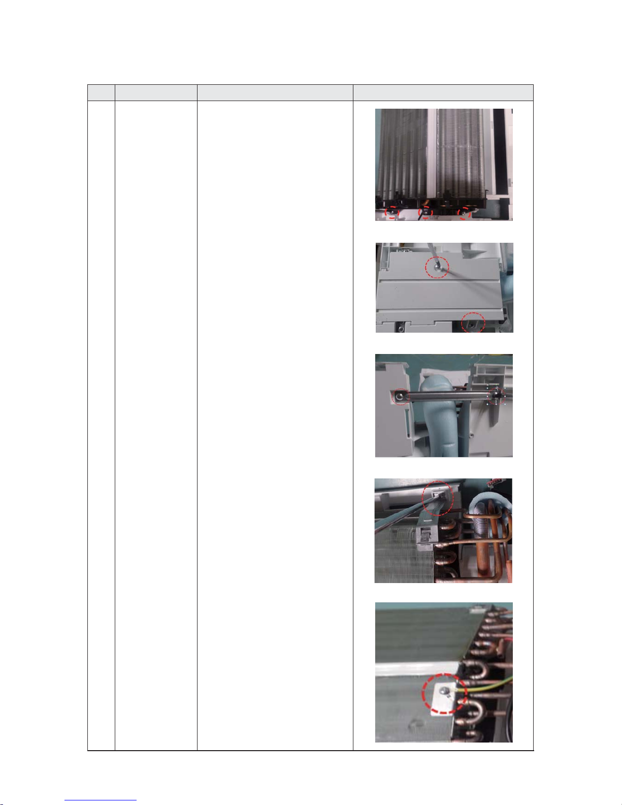
5 EVAPORATOR 9) Take off the CASE-CONTROL from
the main frame after loosen the remaining
connector.
Caution:
When you separate the connector,
pull pressing the locking button.
3 TRAY DRAIN 1) To detach TRAY-DRAIN from the main frame,
pull the bottom of the TRAY-DRAIN towards
you.
Samsung Electronics 3-9
No Parts
Procedure Remark
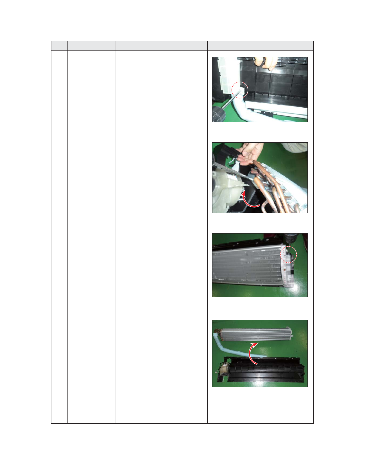
4 Evaporator 1) Detach the HOLDER PIPE.
2) Unfasten the screw at the left side.
(use + Screw Driver)
3) Unfasten the screw at the right side.
(use + Screw Driver)
4) To detach Evaporator from the main frame,
pull the bottom of the Evaporator towards
you.
3-10 Samsung Electronics
No Parts
Procedure Remark
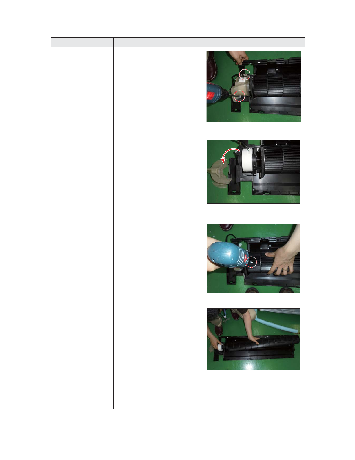
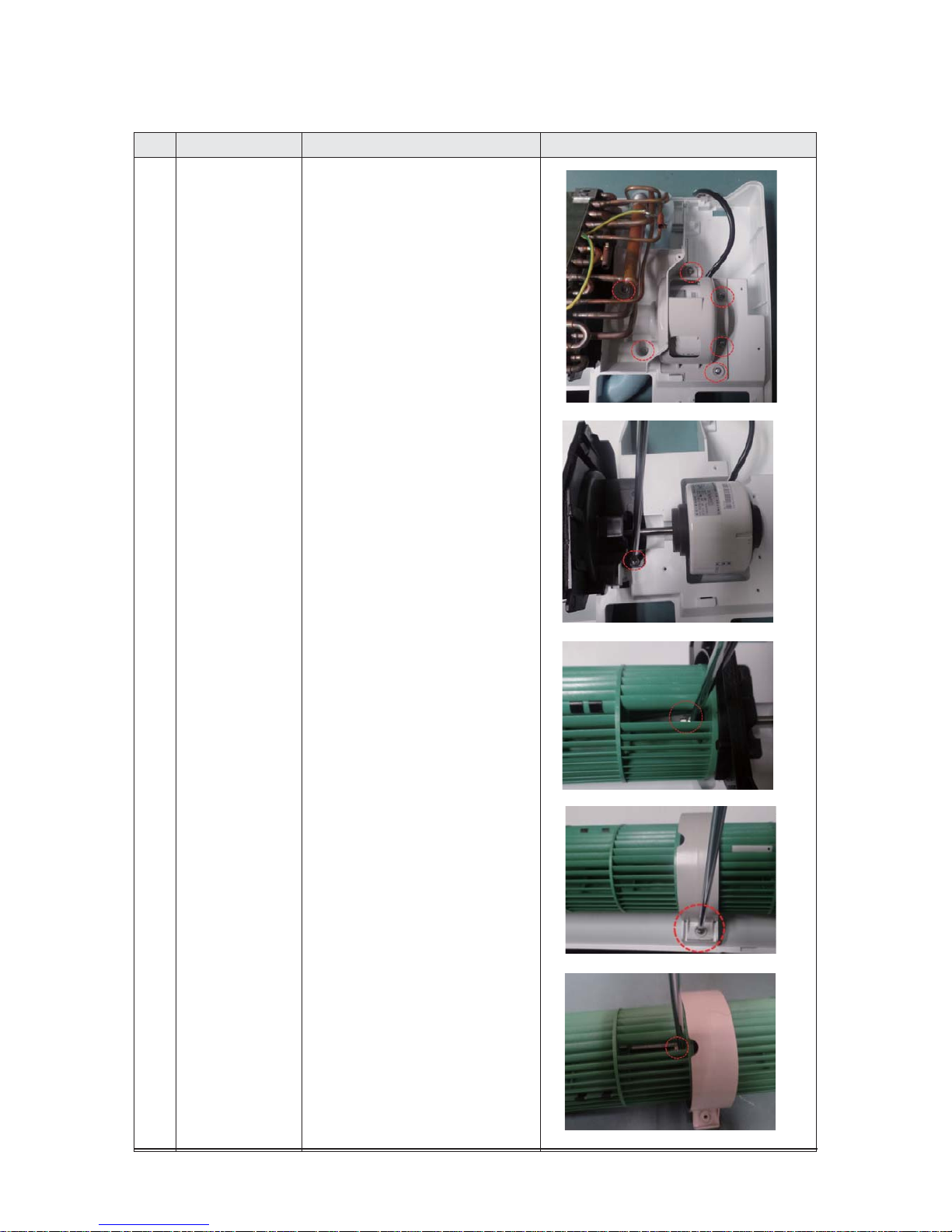
5 FAN MOTOR
&
CROSS FAN
1) Unfasten the screw. (use + Screw Driver)
2) Detach the FAN Motor case.
3) Unfasten the screw a little.
(use + Screw Driver)
4) Pull the CROSS-FAN to the left side.
Samsung Electronics 3-11
XAC030MNTDCH / AC036MNTDCH
No Parts
Procedure Remark
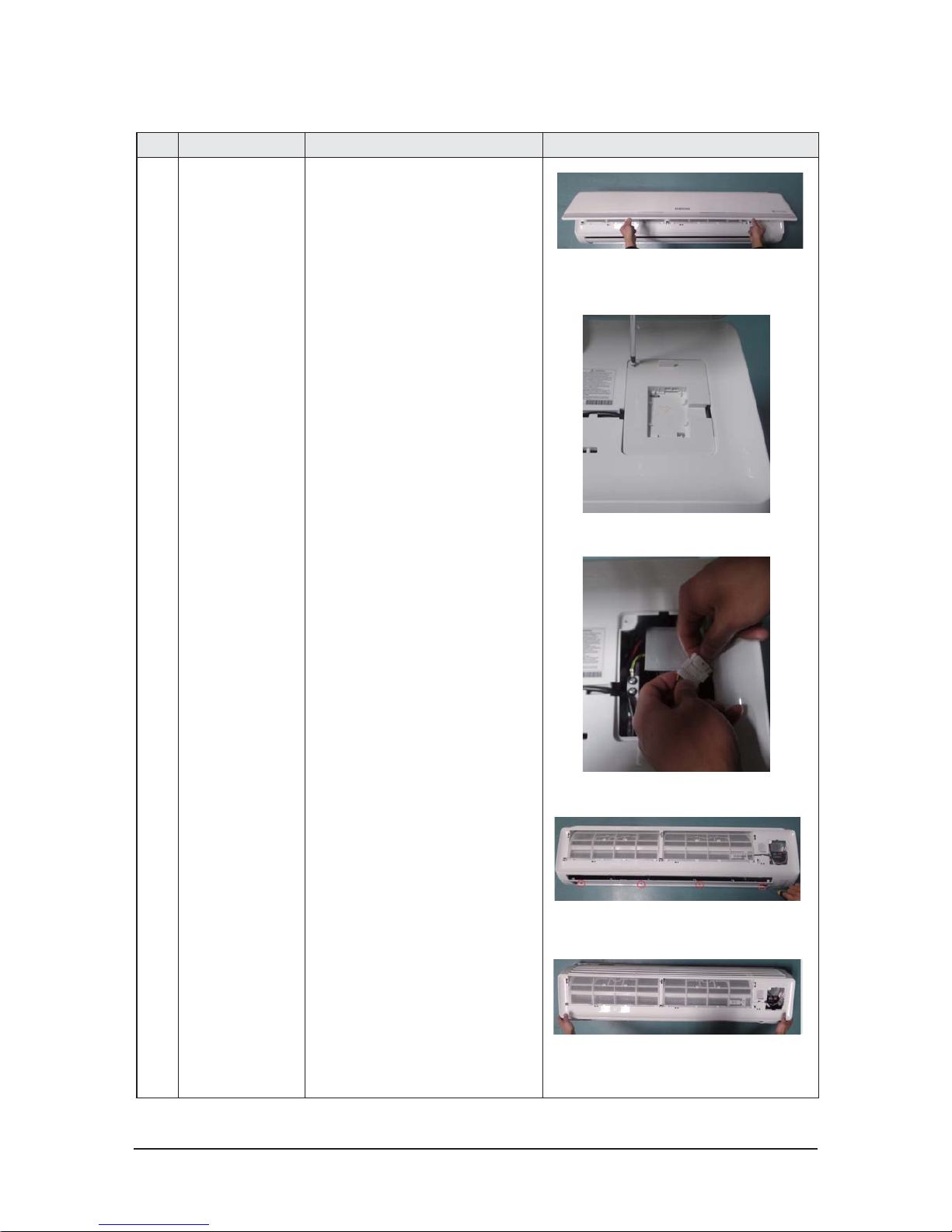
1 PANEL-FRONT 1) Stop the driving of air conditioner and shut off
main power supply.
2) Open the FRONT-GRILLE and pull out from the
PANEL-FRONT.
3) Detach COVER-TERMINAL from the PANEL
FRONT. (use + Screw Driver)
4) Loosen connector wire(white) and detach the
temperature sensor wire .
5) To detach the FRONT-PANELthe main frame,
unfasten 2 screw at the bottom.(use + Screw
Driver )
6) Take off the FRONT-PANEL,lifting up the bottom
3-12 Samsung Electronics
No Parts
Procedure Remark
2
TRAY DRAIN
1) Loosen stepping motor wire and detach the
hook of main frame.
2) To detach TRAY-DRAIN from the main frame, pull
the bottom of the TRAY-DRAIN towards you.
3) To detach TRAY-DRAIN from the main frame ,
pull the bottom of the TRAY-DRAIN towards you.
3
CONTROL IN
1) Unfasten the earth screw.(use + ScrewDriver)
2) Detach the temperature sensor and Humidity
sensor.
3) Detach the temperature sensor.
Samsung Electronics 3-13
No Parts
Procedure Remark
4) Loosen MOTOR wires(white).
5) Take off the CASE-CONTROL from the main
frame. (use + Screw Driver)
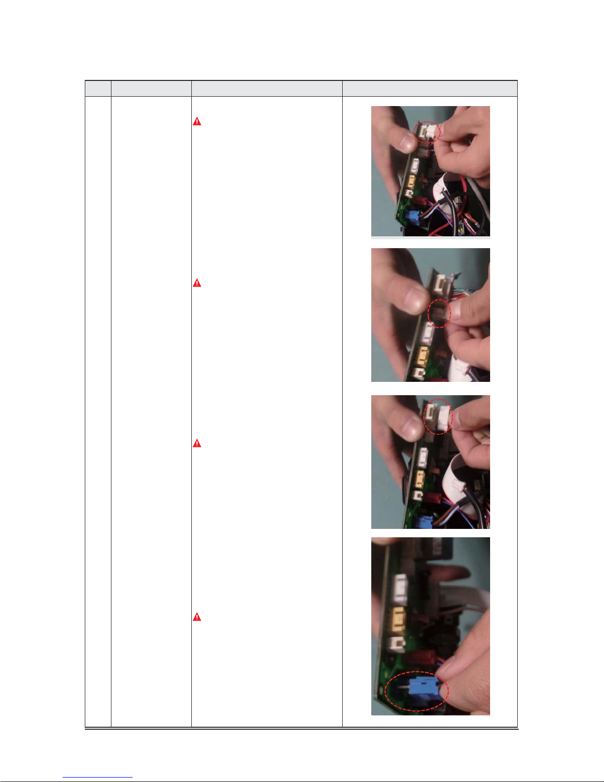
4 PBA 1) Loosen the STEP UP/DOWN connector(CN802).
Caution:
When you separate the connector,
pull pressing the locking button.
2) Loosen the FUSE CHK connector (CN140).
Caution:
When you separate the connector,
pull pressing the locking button.
3-14 Samsung Electronics
No Parts
Procedure Remark
3) Loosen the EVA IN/OUT connector. (CN403)
Caution:
When you separate the connector,
pull pressing the locking button.
4) Loosen the Humidity sensor connector(CN401).
->Option connector.
Caution:
The terminal is locking type.
So, when you separate terminals, pull pressing
the button.
5) Loosen the DISPLAY connector. (CN501).
Caution:
The terminal is locking type.
So, when you separate terminals, pull pressing
the button.
6) Loosen the POWER connector.
Caution:
When you separate the connector,
pull pressing the locking button.
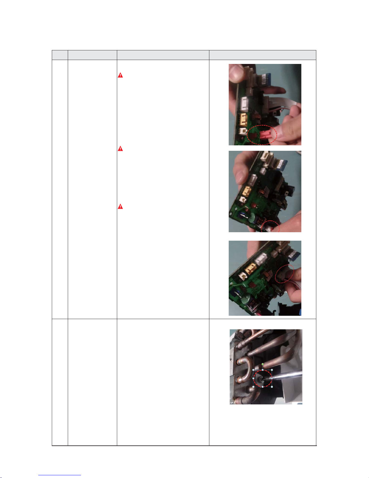
Samsung Electronics 3-15
No Parts
Procedure Remark
7) Loosen the COMM wire connector(CN303).
Caution:
When you take off the PBA, don’t touch
the components.
Please hold the PBA both side.
8) Loosen the Motor connector(CN701).
Caution:
When you separate the connector,
pull pressing the locking button.
9) Take off the main PBA from the ASS’Y Control in.
Caution:
When you take off the PBA, don’t touch
the components.
Please hold the PBA both side.
5 EVAPORATOR 1) Unfasten the screw at the right side. (use +
ScrewDriver)
3-16 Samsung Electronics
No Parts
Procedure Remark
2) Unfasten the screw at the left side. (use +
ScrewDriver)
3) Detach the HOLDER PIPE. (use + Screw Driver)
4) Detach the BRACKET-EVAP. (use + Screw Driver)
5) Detach the HOLDER EVAP. (use + Screw Driver)
6) Loosen 1 fixing earth screw right side. (use +
Screw Driver)
Samsung Electronics 3-17
No Parts
Procedure Remark
6 FAN MOTOR
&
CROSS FAN
1) Loosen 6 fixing screws of HOLDER-MOTOR
2) unfasten the screw a little. (use + Screw Driver)
3) unfasten the screw a little and pull the MOTOR
FAN to the right side. (use + Screw Driver)
4) Loosen 1 fixing screws of HOLDER-FAN.(use +
Screw Driver)
5) unfasten the screw a little.(use + Screw Driver)
3-18 Samsung Electronics
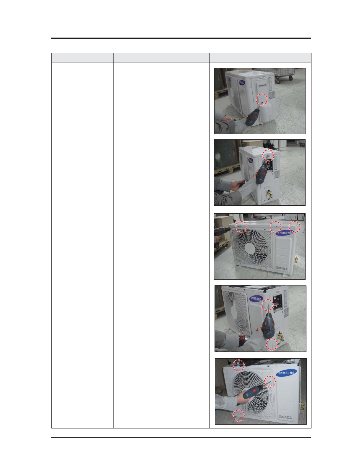
■ AC012KXADCH
No Parts Procedure Remark
1 common work 1) loosen 1 pcs screw of cover control,and
detach it.
2) loosen 5 pcs screws on both right and
left cabniet side edges and to detach the
cover-top
3) Loosen 7 screwsfixed to disassemble
cabi-front , and detach it.
3-2 Outdoor Unit
Samsung Electronics 3-19
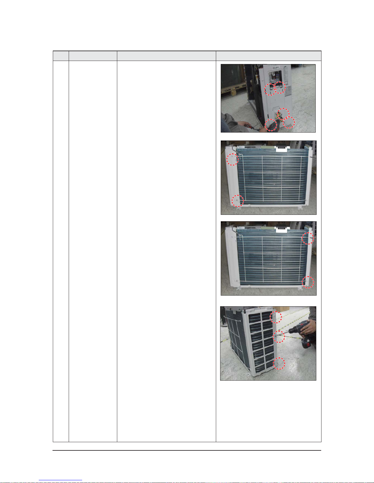
No Parts Procedure Remark
common work 4) loosen 7 screws to disassemble the cabi-
right ,and detach it.
5) loosen 2 screws to disassemble steel-bar.
6) loosen 3 screws to disassemble cabi-left.
3-20 Samsung Electronics
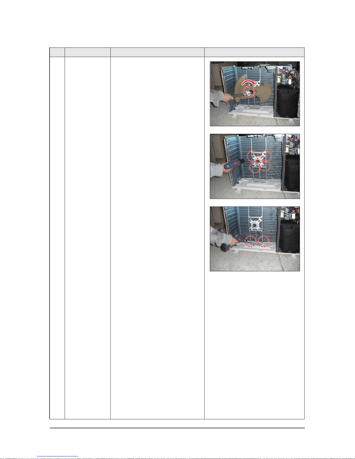
No Parts Procedure Remark
2 fan&motor 1) loosen 1 screw as indication and detached
the fan.
2) loosen 4 pcs motor screws and disconnect
the wire betwwen assy control out and motor.
3) loosen 2 pcs bracket-motor screw and
detach it.
 Loading...