

Samsung AC035HCADKH, AC071HBLDKH, AC035HBMDKH, AC071HCADKH, AC060HBMDKH Service Manual
...
AIR CONDITIONER CONTENTS
SYSTEM AIR CONDITIONER
Indoor Unit
Outdoor Unit
Model
:
AC052HBLDKH AC052HCADKH
AC071HBLDKH AC071HCADKH
AC035HBMDKH AC035HCADKH
AC052HBMDKH AC052HCADKH
AC060HBMDKH AC060HCADKH
AC071HBMDKH AC071HCADKH
Model Code :
AC052HBLDKH/EU AC052HCADKH/EU
AC071HBLDKH/EU AC071HCADKH/EU
AC035HBMDKH/EU AC035HCADKH/EU
AC052HBMDKH/EU AC052HCADKH/EU
AC060HBMDKH/EU AC060HCADKH/EU
AC071HBMDKH/EU AC071HCADKH/EU
1. Precautions
2. Product Specications
3. Disassembly and Reassembly
4. Troubleshooting
5. PCB Diagram
6. Wiring Diagram
7. Reference Sheet
AC035HBMDKH
AC052HBMDKH
AC052HBLDKH
AC071HBLDKH
AC060HBMDKH
AC071HBMDKH
AC060HCADKH
AC071HCADKH
AC052HCADKHAC035HCADKH

Contents
11. Precautions
........................................................................................................................................
1-1
1-1 Precautions for the Service
.............................................................................................................
1-1
1-2 Precautions for the Static Electricity and PL
................................................................................
1-1
1-3 Precautions for the Safety
...............................................................................................................
1-1
1-4 Others
..................................................................................................................................................
1-1
12. Product Specifications
...............................................................................................................
2-1
2-1 The Feature of Product
....................................................................................................................
2-1
2-2 Product Specifications
.....................................................................................................................
2-2
2-3 Accessory
...........................................................................................................................................
2-5
3. Disassembly and Reassembly
..............................................................................................
3-1
3-1 Indoor Unit
.........................................................................................................................................
3-2
3-2 Outdoor Unit
.....................................................................................................................................
3-13
4. Trouble shooting
...........................................................................................................................
4-1
4-1 Indoor Display Error and Check Method
.....................................................................................
4-1
4-2 Outdoor Trouble shooting
.............................................................................................................
4-6
4-3 Setting Option Setup Method
........................................................................................................
4-11
4-4 Items to be checked first
.................................................................................................................
4-13
4-5 Fault Diagnosis by Symptom
.........................................................................................................
4-14
4-6 PCB Inspection Method
...................................................................................................................
4-29
4-7 Troubleshooting by symptoms
......................................................................................................
4-32
4-8 Main Part Inspection Method
.........................................................................................................
4-40
5. PCB Diagram and Parts list
......................................................................................................
5-1
6. Wiring Diagram
..............................................................................................................................
6-1
6-1 Indoor Unit ............................................................................................................................................................ 6-1
6-2 Outdoor Unit ........................................................................................................................................................ 6-3
7. Reference Sheet
.............................................................................................................................
7-1
7-1 Refrigerating Cycle Diagram
..........................................................................................................
7-1
7-2 Index for Model Name
.....................................................................................................................
7-2

Samsung Electronics 1-1
1. Precautions
1-1 Precautions for the Service
f Use the standard parts when replacing the electric parts.
– Confirm the model name, rated voltage, rated current of the electric parts.
f Repair the disconnection of HARNESS securely when repairing the break down.
– If there is any connection error, it causes an abnormal noise and incorrect operation.
f In case that you assemble or disassemble the products with laying it on the side, do work on the work cloth.
– If not, the exterior of products can be scratched.
f
Remove dust and foreign materials from harness, connection part, and inspection part thoroughly when repairing the break down.
– It protects the danger of fire such as tracking and short.
f Tighten tightly the service valve of outdoor unit and the cap of charging valve with a monkey spanner.
f Check the assembly status of parts after repairing the break down.
– It should be same as the status before repairing.
1-2 Precautions for the Static Electricity and PL
f As the PCB power terminal has a weakness for the static electricity, pay attention to it during the repair and measurement.
– Work with insulation gloves during the repair and measurement of PCB.
f
Check the distance between the product and the other electronic appliances such as TV, video, and audio. It should be over 2m.
– If not, it causes a bad picture quality or a noise.
f Repairing the products by consumer should be strictly prohibited.
– There is a danger of electric shock or fire due to incorrect disassembly.
1-3 Precautions for the Safety
f Do not pull any electric wires and do not touch an auxiliary power switch with a wet hand.
– There is a danger of electric shock or fire.
f In case any wire or power plug has been damaged, replace it to eliminate any possible danger.
f Do not bend the power cord by force and do not put any heavy object on the power cord.
– There is a danger of electric shock or fire.
f Do not use multi socket.
– There is a danger of electric shock or fire.
f Ground the product if necessary.
– Be sure to ground the product if there is any danger of electric leakage due to water or moisture.
f Be sure to turn off the auxiliary power switch or pull out the power plug during replacement or repair of electric parts.
– There is a danger of electric shock.
f In case the product will not be in use for a long time, the battery of remote control should be kept separately.
– Leakage of inside fluid can cause break down of remote control.
1-4 Others
f Never store or load the air conditioner upside down or sideways to prevent the damage to the compressor.
f Young children or infirm persons should be always supervised when they use the air conditioner.
f Max current is measured according to IEC standard for safety.
f Current is measured according to ISO standard for energy efficiency.
f
When installing, make sure there is no leakage. When recovering the refrigerant, ground the compressor first before removing the
connection pipe. If the refrigerant pipe is not properly connected and the compressor works with the service valve open, the pipe
inhales the air and it makes the pressure inside of the refrigerant cycle abnormally high. It may cause explosion and injury.
f Pump Down Procedure (When removing the product)
- Turn on the air conditioner and select Cool mode to run the compressor for 3 minutes.
- Release the valve caps on High and Low pressure side.
- Use L wrench to close the valve on the high pressure side.
- Approximately 2 minutes after, close the valve on the low pressure side.
- Stop operation of the air conditioner.
- Disconnect the pipes.

Samsung Electronics2-1
2. Product Specifications
2-1 The Feature of Product
■ Built-in Duct Type
After installed, the air conditioner can be harmonized with a room interior.
■ High Performance & Energy Saving
With the advanced BLDC inverter technology, it makes a room cool with highly energy saving and arises the efficiency of air
conditioner.
■ Long Piping (Length & Height)
It can give the benefit to the installers and aries the reliability of the air conditioner.
■ Long Ambient Operation (In Low Temperature)
It can arise the reliability and the capacity of the air conditioner, especially operated in low temperature.
■ Eco-friendly Product (Lead-Free, RoHS, WEEE)
Samsung Electronics 2-2
2-2 Product Specifications
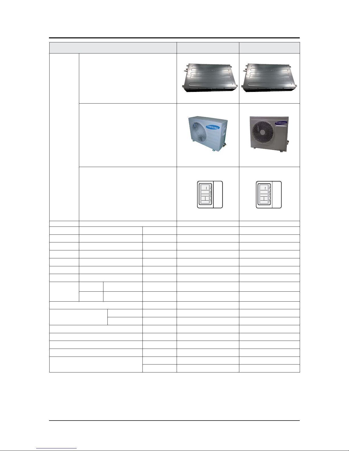
ITEM
AC052HBLDKH
AC052HCADKH
AC071HBLDKH
AC071HCADKH
IMAGE
Indoor Unit
Outdoor Unit
Remote Controller
MWR-WE10 MWR-WE10
Power
Product 1Φ, 220~240V/50Hz 1Φ, 220~240V/50Hz
Indoor
L x H x D mm
1100*200*450 1100*200*450
Outdoor
L x H x D mm
880*638*310 880*798*310
Indoor
Product kg(Net) 22.5
22.5
Outdoor
Product kg(Net) 45.0 55
Capacity
Cooling/Heating(ISO) W 5000 / 6000 7100/8000
Power input
Cooling/Heating (ISO) W
1560 / 1660 2210/2300
Operation current
Cooling/Heating (ISO) A
7.2 / 7.5 9.8/10.2
Noise
(Cooling/Heating)
Indoor unit
In case of strongest air
blow
dB 45
47
Outdoor unit
In case of strongest air
blow
dB
58 60
Refrigerant (R410A)
g 1300 1500
Connecting Pipe
Liquid mm 1/4"(6.35) 1/4"(6.35)
Gas mm 1/2"(12.7) 5/8"(15.88)
Additional Refrigerant (R410A)
g/m 10 20
Standard
m5
5
Extension length(Total)
m30 30
Extension length(Elevation)
m20 15
Option Code
Product Option
01C06C-1C5925-27323C-370000 01C06C-1C59E8-274750-370000
Installation Option
020000-100000-200000-300000 020000-100000-200000-300000
Samsung Electronics
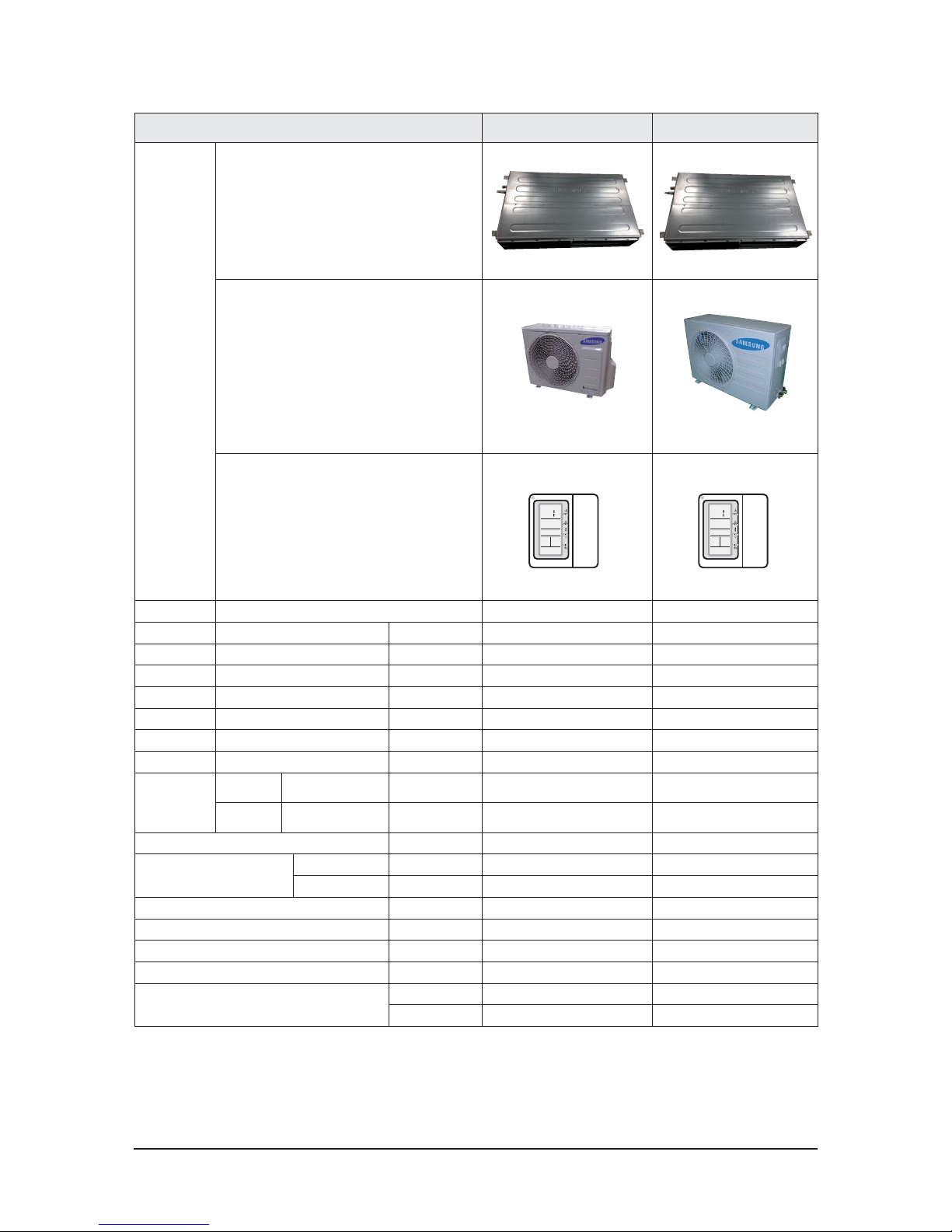
ITEM
AC035HBMDKH
AC035HCADKH
AC052HBMDKH
AC052HCADKH
IMAGE
Indoor Unit
Outdoor Unit
Remote Controller
MWR-WE10 MWR-WE10
Power Product
1Φ, 220-240V~/50Hz 1Φ, 220~240V/50Hz
Indoor L x H x D mm
850*250*700 1100*200*450
Outdoor L x H x D mm
720*548*265 880*638*310
Indoor Product kg(Net)
25 22.5
Outdoor Product kg(Net)
29.5 45.0
Capacity Cooling/Heating(ISO) W
3500 / 4000 5000 / 6000
Power input Cooling/Heating (ISO) W
1100 / 1020 1560 / 1660
Operation current Cooling/Heating (ISO) A
5.1 / 4.7 7.2 / 7.5
Noise
(Cooling/Heating)
Indoor unit
In case of strongest air
blow
dB
40 45
Outdoor unit
In case of strongest air
blow
dB
53 58
Refrigerant (R410A) g
900 1300
Connecting Pipe
Liquid mm
1/4"(6.35) 1/4"(6.35)
Gas mm
3/8"(9.52) 1/2"(12.7)
Additional Refrigerant (R410A) g/m
-5
Standard m
55
Extension length(Total) m
20 30
Extension length(Elevation) m
15 20
Option Code
Product Option
01B06C-1C5552-272328-374000
01B06C-1C55A4-27323C-373000
Installation Option
020000-100000-200000-300000
020000-100000-200000-300000
2-3
Samsung Electronics
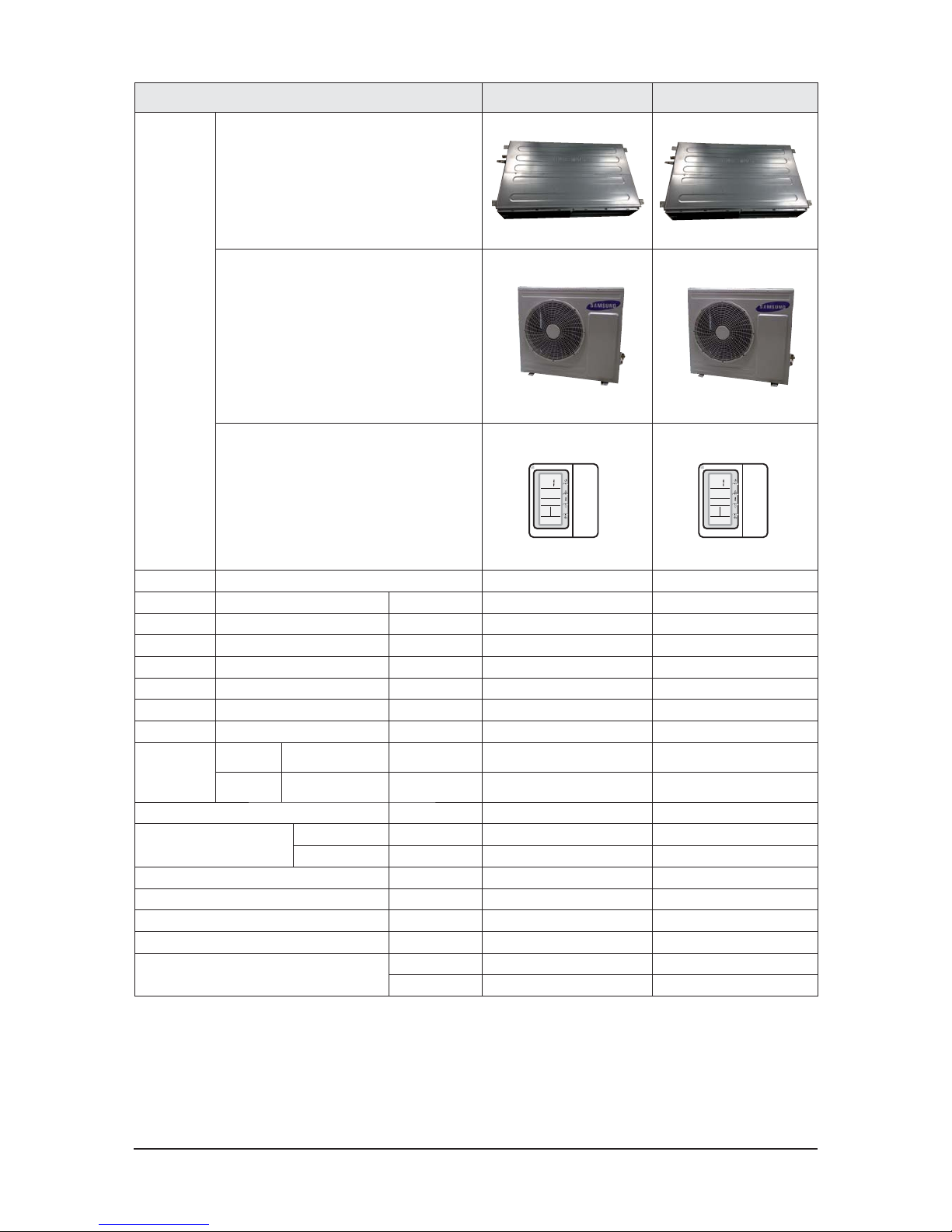
ITEM
AC060HBMDKH
AC060HCADKH
AC071HBMDKH
AC071HCADKH
IMAGE
Indoor Unit
Outdoor Unit
Remote Controller
MWR-WE10 MWR-WE10
Power Product
1Φ, 220~240V/50Hz 1Φ, 220~240V/50Hz
Indoor L x H x D mm
1100*200*450 1100*200*450
Outdoor L x H x D mm
880*798*310 880*798*310
Indoor Product kg(Net)
22.5 22.5
Outdoor Product kg(Net)
55 55
Capacity Cooling/Heating(ISO) W
6000 / 7000 7100/8000
Power input Cooling/Heating (ISO) W
1760 / 1890 2210/2300
Operation current Cooling/Heating (ISO) A
7.9 / 8.4 9.8/10.2
Noise
(Cooling/Heating)
Indoor unit
In case of strongest air
blow
dB
46 47
Outdoor unit
In case of strongest air
blow
dB
58 60
Refrigerant (R410A) g
1500 1500
Connecting Pipe
Liquid mm
1/4"(6.35) 1/4"(6.35)
Gas mm
5/8"(15.88) 5/8"(15.88)
Additional Refrigerant (R410A) g/m
20 20
Standard m
55
Extension length(Total) m
50 50
Extension length(Elevation) m
30 30
Option Code
Product Option
01B06C-1C592B-273C46-372005 01B06C-1C593C-274750-371005
Installation Option
020000-100000-200000-300000 020000-100000-200000-300000
2-4

Samsung Electronics2-5
2-6
2-3 Accessory
Item
Descriptions Code-No. Q'TY Remark
Installation&Owner's Manual
DB68-04233A/ DB68-04234A
1
Indoor
Unit
Insulation
DB62-04318S
1
Insu DRAIN HOSE DB62-11028A 1/1/1
INSU HOSE D
DB62-11028E
1/1
INSU TUBE OUT
DB62-11028F
1/1
ASSY DRAIN HOSE JOINT
DB67-01191A
1
Ass'y Drain Hose Joint
DB90-06701A
1
GROMMET-HANGER
DB63-00237A
8
RUBBER LEG DB73-20134A 4
Outdoor unit
INSTALLATION MANUAL
DB68-04465A
1
DRAIN PLUG
DB73-20134A
1
O
W
N
ER
'
S
I
N
S
T
R
U
C
T
I
O
N
S
M
A
N
U
A
L
D
E
I
N
ST
R
U
C
C
I
O
N
ES
I
STR
U
Z
I
O
N
I
P
ER
L'
U
SO
MA
N
U
A
L
D
E
I
N
STR
U
‚
Í
ES
M
A
N
U
EL
D
'
U
TI
L
I
SA
T
I
O
N
G
E
B
R
A
U
C
H
SA
N
W
E
I
SU
N
G
S
p
l
u
t
-
ty
p
e
R
o
om
A
i
r
C
o
n
di
ti
on
e
r
A
i
r
e
a
c
on
d
i
c
i
o
n
a
d
o
d
o
ms
ti
c
o
s
i
s
te
ma
S
pl
i
t
C
ondi
z
i
o
na
to
r
e
d'
a
r
i
a
pe
r
a
m
bi
e
nti
a
d
un
i
tˆ
S
e
pa
r
a
te
A
p
a
r
e
l
h
o
d
e
a
r
c
o
ndi
c
i
ona
d
o
ti
p
o
S
pl
i
t
C
l
i
m
a
ti
s
e
ur
de
ty
p
e
s
pa
r
G
e
te
i
l
te
r
a
um
k
l
i
m
a
a
nl
a
g
e
O
W
N
ER
'
S
I
N
S
TR
U
C
T
I
O
N
S
M
A
N
U
A
L
D
E
I
N
ST
R
U
C
C
I
O
N
ES
I
STR
U
Z
I
O
N
I
P
ER
L
'
U
SO
M
A
N
U
A
L
D
E
I
N
STR
U
‚
Í
ES
M
A
N
U
EL
D
'
U
TI
L
I
S
A
T
I
O
N
G
E
B
R
A
U
C
H
S
A
N
W
EI
SU
N
G
S
p
l
u
t-
t
y
p
e
R
o
o
m
A
i
r
C
on
d
i
t
i
on
e
r
A
i
r
e
a
c
o
n
di
c
i
on
a
d
o
d
o
m
s
t
i
c
o
s
i
s
te
m
a
S
p
l
i
t
C
ondi
z
i
o
n
a
to
r
e
d
'
a
r
i
a
pe
r
a
m
b
i
e
nti
a
d
u
n
i
t
ˆ
S
e
pa
r
a
t
e
A
p
a
r
e
l
h
o
d
e
a
r
c
on
d
i
c
i
o
n
a
d
o
t
i
p
o
S
p
l
i
t
C
l
i
m
a
t
i
s
e
u
r
d
e
t
y
p
e
s
pa
r
G
e
te
i
l
t
e
r
a
um
k
l
i
m
a
a
n
l
a
g
e
Samsung Electronics 3-1
3. Disassembly and Reassembly
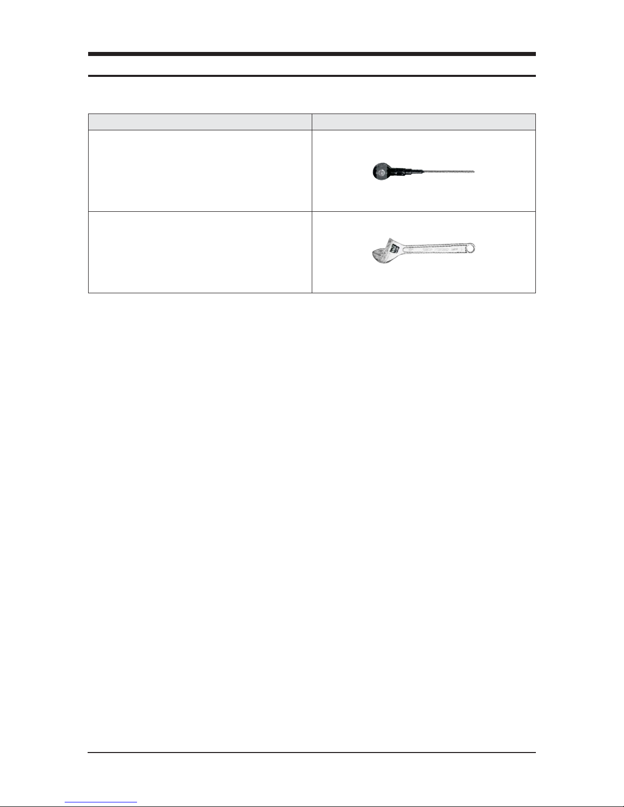
■ Necessary Tools
Item Remark
+SCREW DRIVER
MONKEY SPANNER
3-2 Samsung Electronics
3-1 Indoor Unit
■AC035HBMDKH/ AC052HBMDKH/ AC060HBMDKH/ AC071HBMDKH
No Parts Procedure Remark
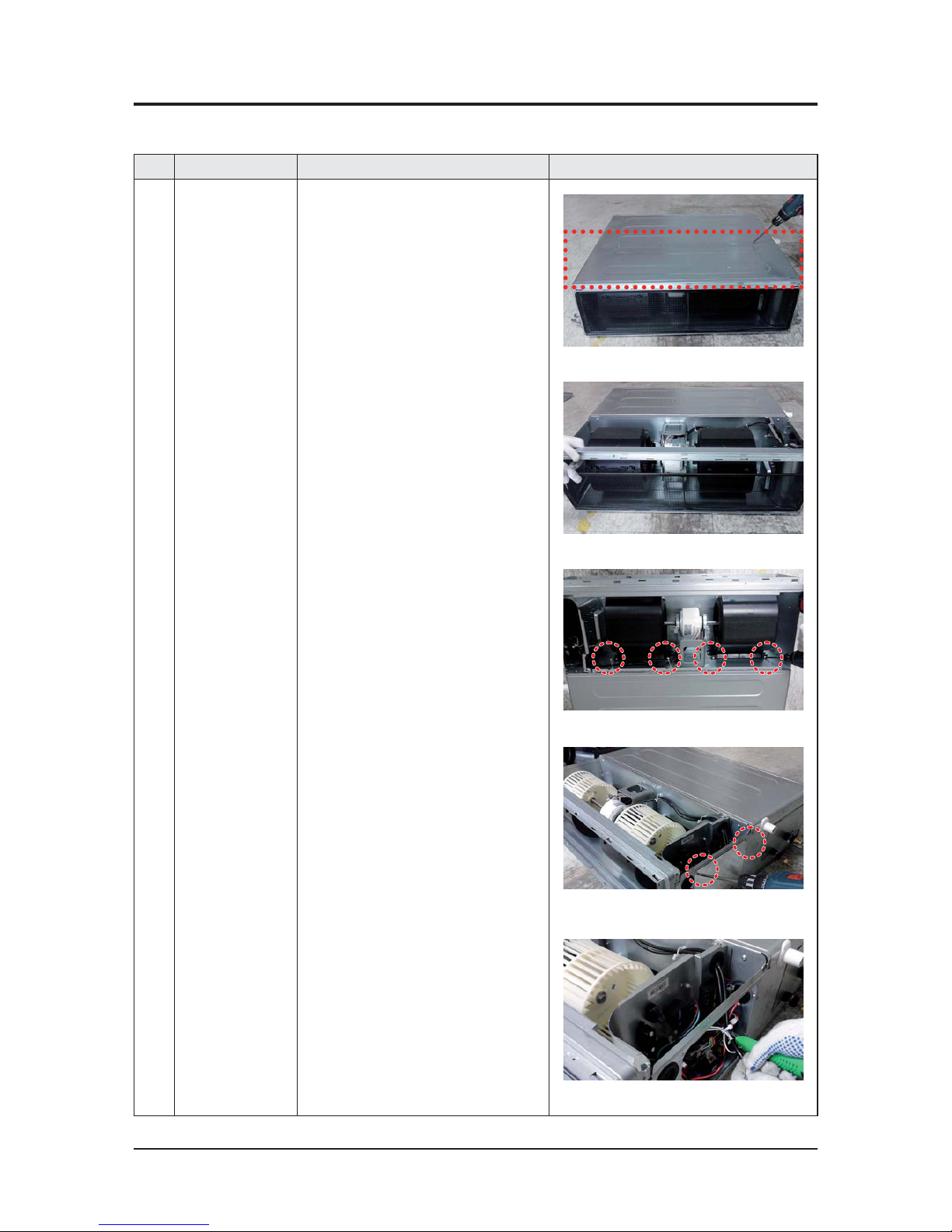
1 Motor
&
Blower
1)Disassemble the Cabinet Bottom Fan.
- Unscrew 10 screws
2)Disassemble the Case Filter Pre.
3)Disassemble the 2 Case Blower Bottom.
- Unscrew 4 screws
4)Disassemble the Cover Control.
- Unscrew 2 screws
5)Cut the cable-tie
Samsung Electronics 3-3
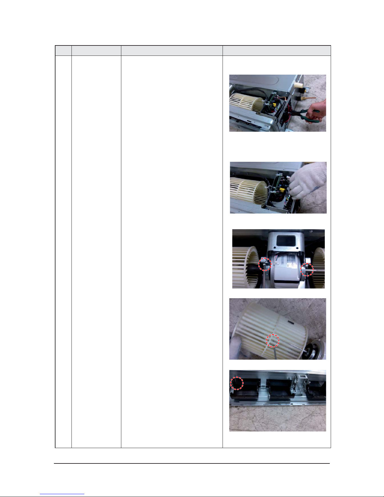
No Parts Procedure Remark
6)Disconnect the wire betwwen assy control
out and motor.
7)Disassemble the 2 Holder Motor.
- Unscrew 2 screws
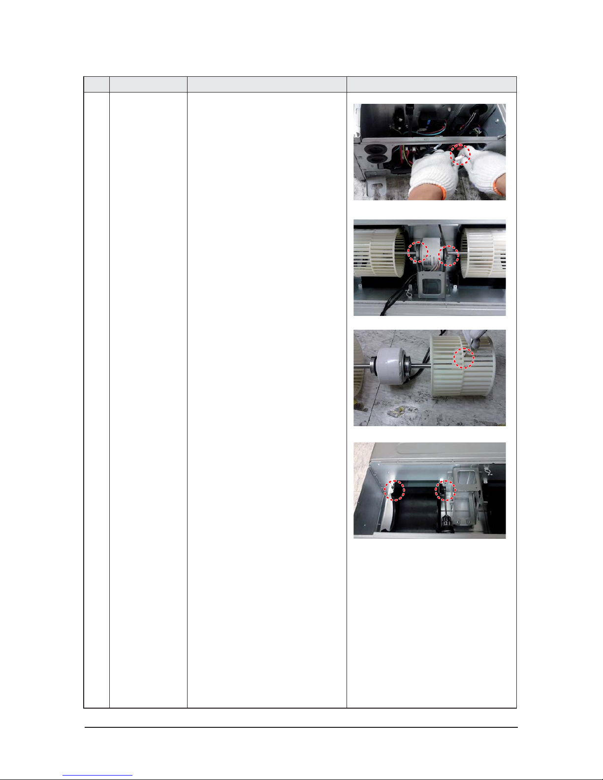
8)After disassembling the Motor and Blower
for the set, disassemble the Blower by use of
3mm wrench.
9)Disassemble the both of Case Blower Out
- Unscrew 4 screws
3-4 Samsung Electronics
No Parts Procedure Remark
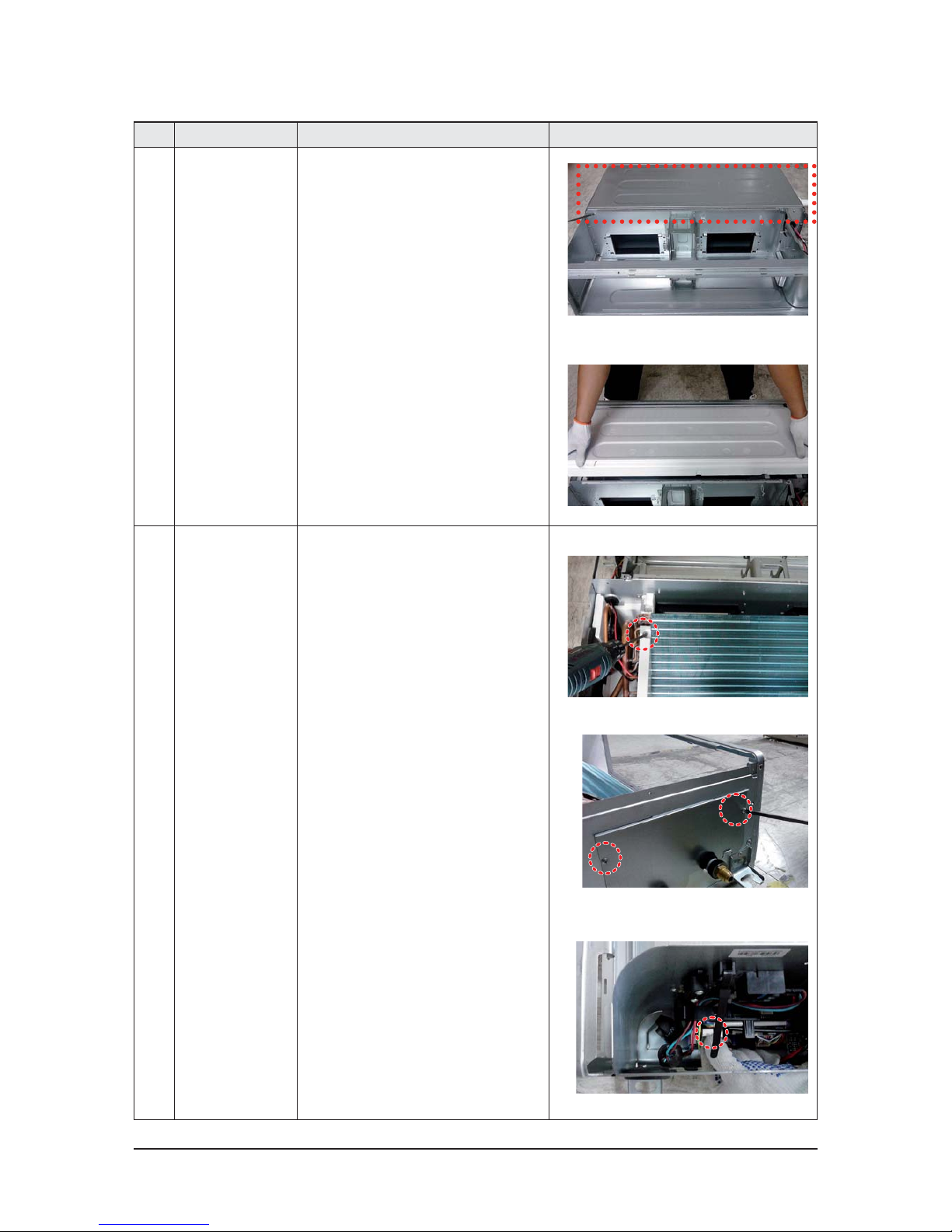
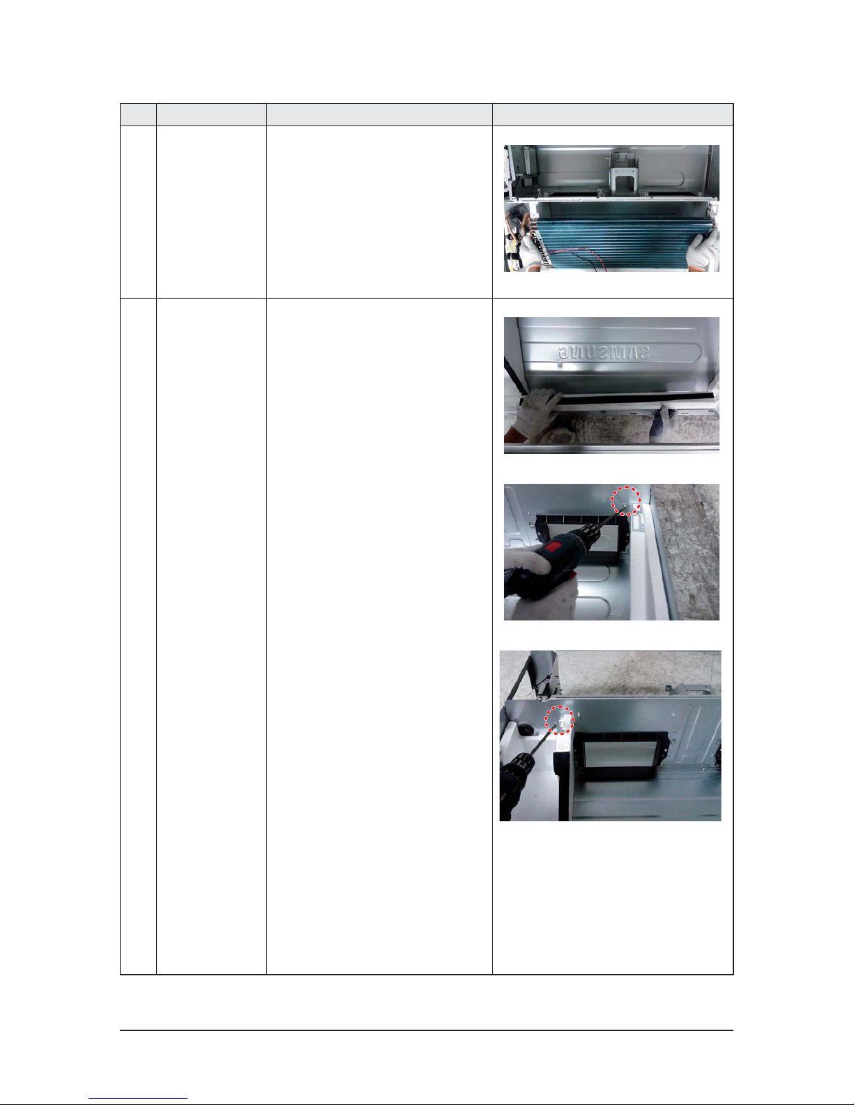
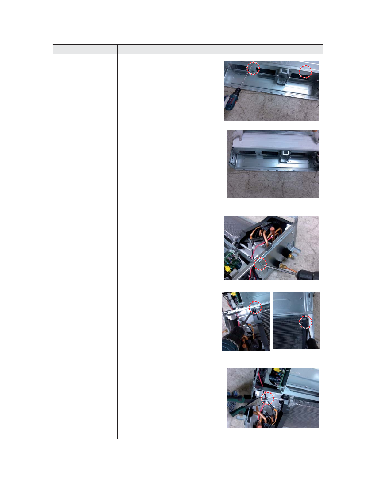
2 Drain Pan 1)Disassemble the Cabinet Bottom Evap.
- Unscrew 7 screws
2)Pull the Drain Pan Out
3 EVAP 1)Disassemble the Support Evap.
- Unscrew 1 screws
2)Disassemble the Cover Pipe.
- Unscrew 2 screws
3)Disconnect the wire betwwen assy control
out and Evap
Samsung Electronics 3-5
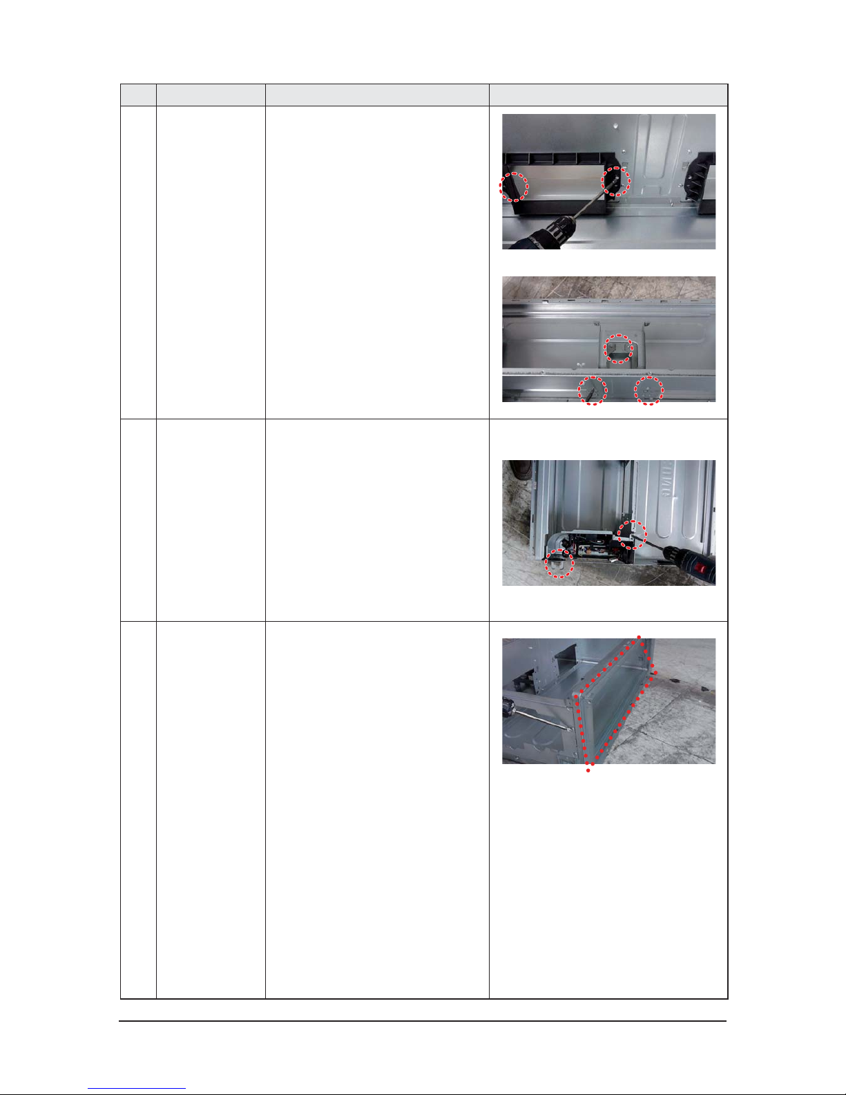
No Parts Procedure Remark
4)Disassemble the Evap.
- Unscrew 3 screws.
Then pull the Evap out
4 Cushion
1)Pull out the Cushion
2)Disassemble the Seal Cushion LF.
- Unscrew 1 screws
3)Disassemble the Assy Cushion Right.
- Unscrew 1 screws
3-6 Samsung Electronics
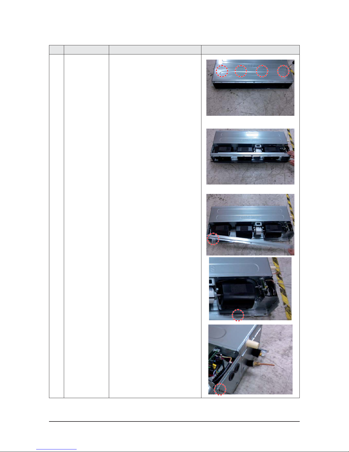
No Parts Procedure Remark
5 Case Blower&Bracket
Motor
1)Disassemble the both of Case Blower Out
- Unscrew 4 screws
2)Disassemble the Bracket Motor.
- Unscrew 6 screws
6 Control 1)Disassemble the Case Control.
- Unscrew 2 screws
7 Frame
1)Disassemble the Frame.
- Unscrew 6 screws
Samsung Electronics 3-7
■AC052HBLDKH/ AC071HBLDKH
No Parts Procedure Remark
1 Motor
&
Blower
1)Disassemble the Cabinet Bottom Fan.
- Unscrew 10 screws
2)Disassemble the Case Filter Pre.
3)Disassemble frame-up
- Unscrew 2 screws
4)Disassemble the case blower
- Unscrew 3 screws
5)Disassemble cover control
- Unscrew 2 screws
3-8 Samsung Electronics
No Parts Procedure Remark
5)Cut the cable-tie
6)Disconnect the wire betwwen assy control
out and motor.
7)Disassemble the 2 Holder Motor.
- Unscrew 2 screws
8)After disassembling the Motor and Blower
for the set, disassemble the Blower by use of
3mm wrench.
9)Disassemble the both of Case Blower Out
- Unscrew 6 screws
Samsung Electronics 3-9
No Parts Procedure Remark
2 Drain Pan 1)Disassemble the Cabinet Bottom Evap.
- Unscrew 7 screws
2)Pull the Drain Pan Out
3 EVAP 1)Disassemble the Cover Pipe.
- Unscrew 2 screws
2)1)Disassemble the Support Evap and hold
evap.
- Unscrew 3 screws
3)Disconnect the wire betwwen assy control
out and Evap
3-10 Samsung Electronics
No Parts Procedure Remark
4)Then pull the Evap out
4 Cushion
1)Pull out the seal Cushion front
2)Disassemble the Seal Cushion Right.
- Unscrew 1 screws
3)Disassemble the Assy Cushion LF.
- Unscrew 1 screws
Samsung Electronics 3-11
No Parts Procedure Remark
5 Bracket Motor 1)Disassemble the Bracket Motor.
- Unscrew 6 screws
6 Control 1) Loosen 2 screws of Assy control in and
Remove the assy control in.
2) Remove wires from wire saddle.
3) clip cable tie.
(It is necessary to re-tie “cable tie” on reassembly,then place in wire saddle .)
3-12 Samsung Electronics
No Parts Procedure Remark
7 Frame
1)Disassemble the Frame.
- Unscrew 4 screws
Samsung Electronics 3-13
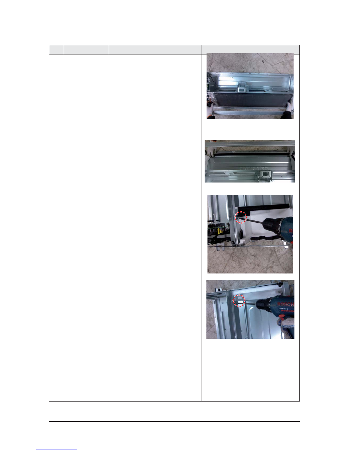
No Parts Procedure Remark
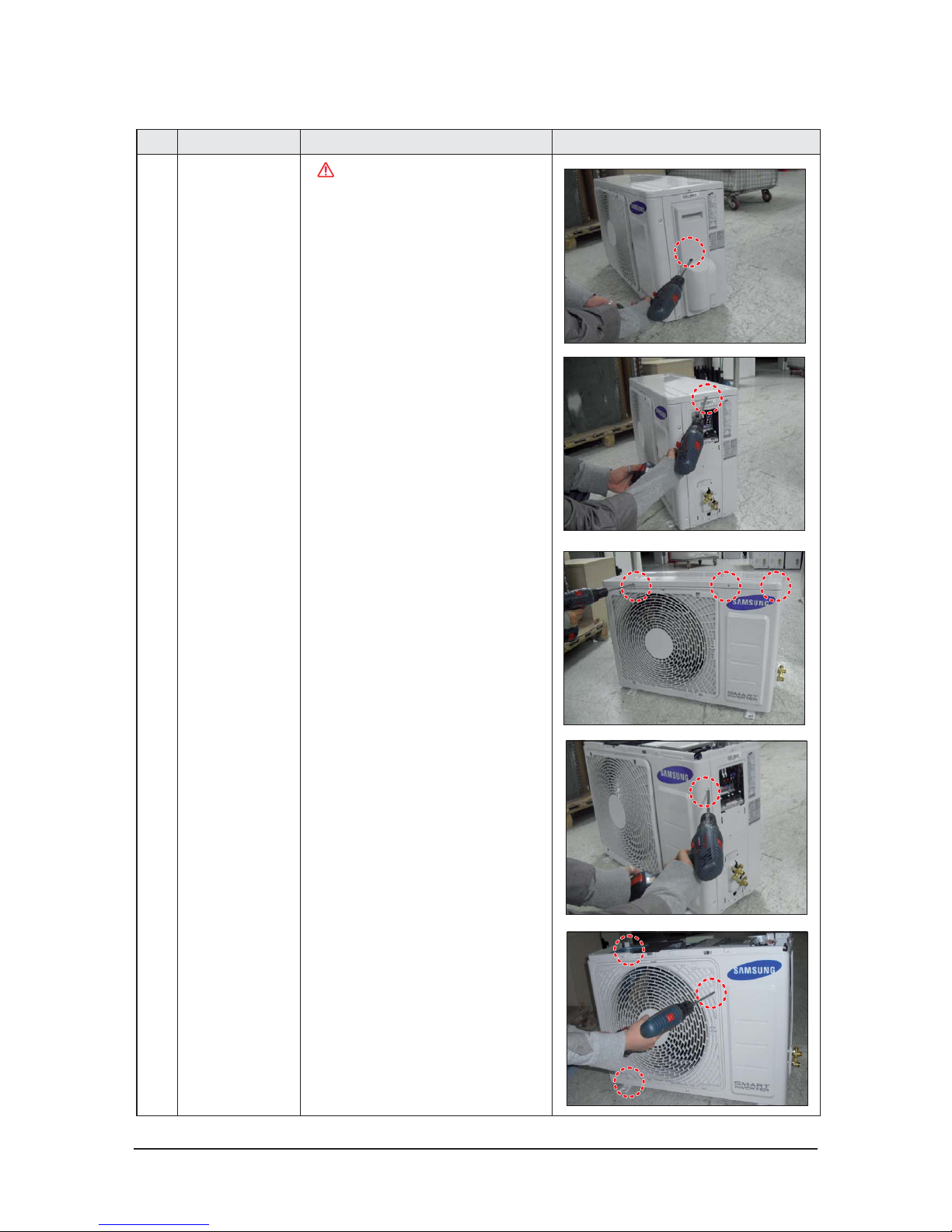
1 common work
You must turn off the Power
before disassembly.
1) loosen 1 pcs screw of cover control,and
detach it.
2) loosen 5 pcs screws on both right and
left cabniet side edges and to detach the
cover-top
3) Loosen 7 screwsfixed to disassemble
cabi-front , and detach it.
3-2 Outdoor Unit
■AC035HCADKH
CAUTION
3-14 Samsung Electronics
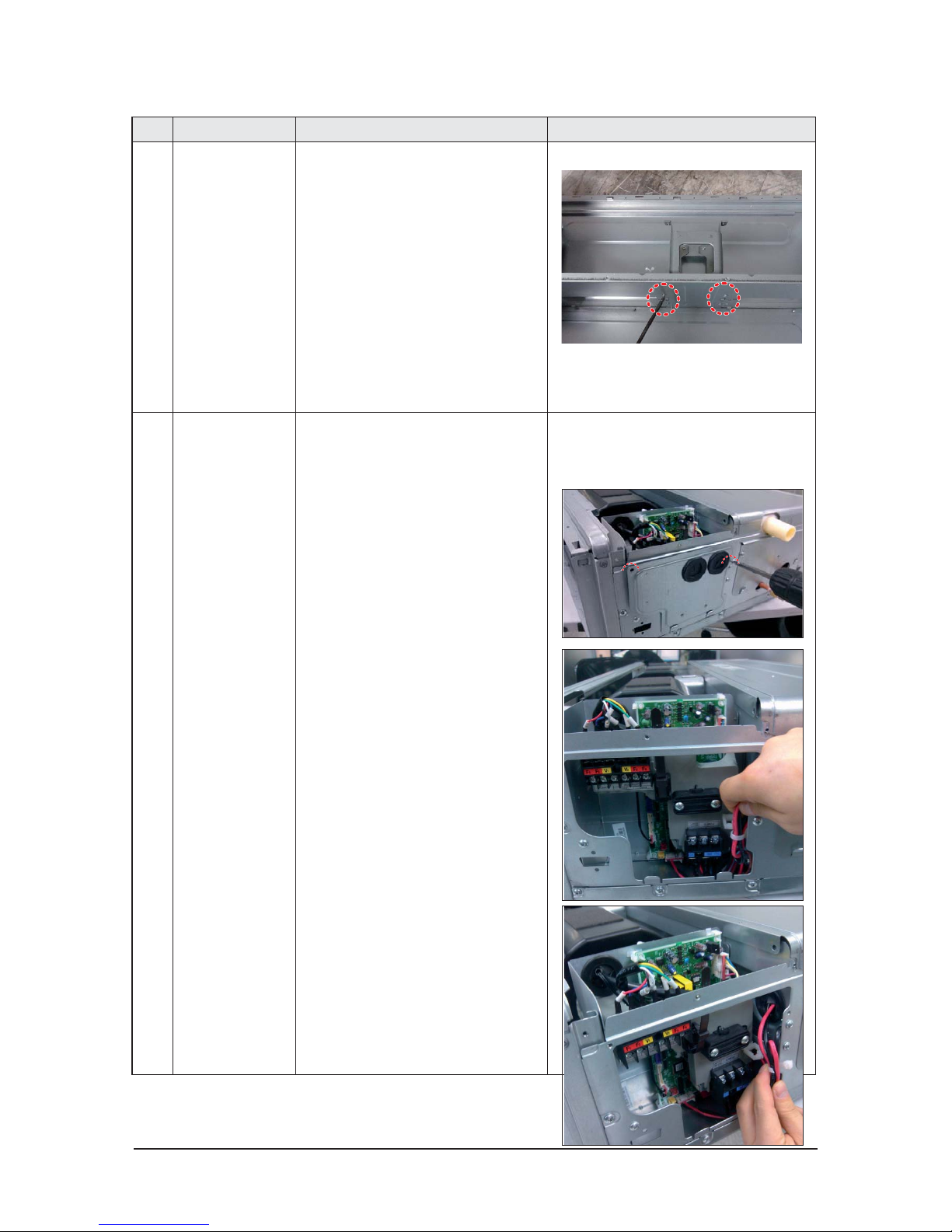
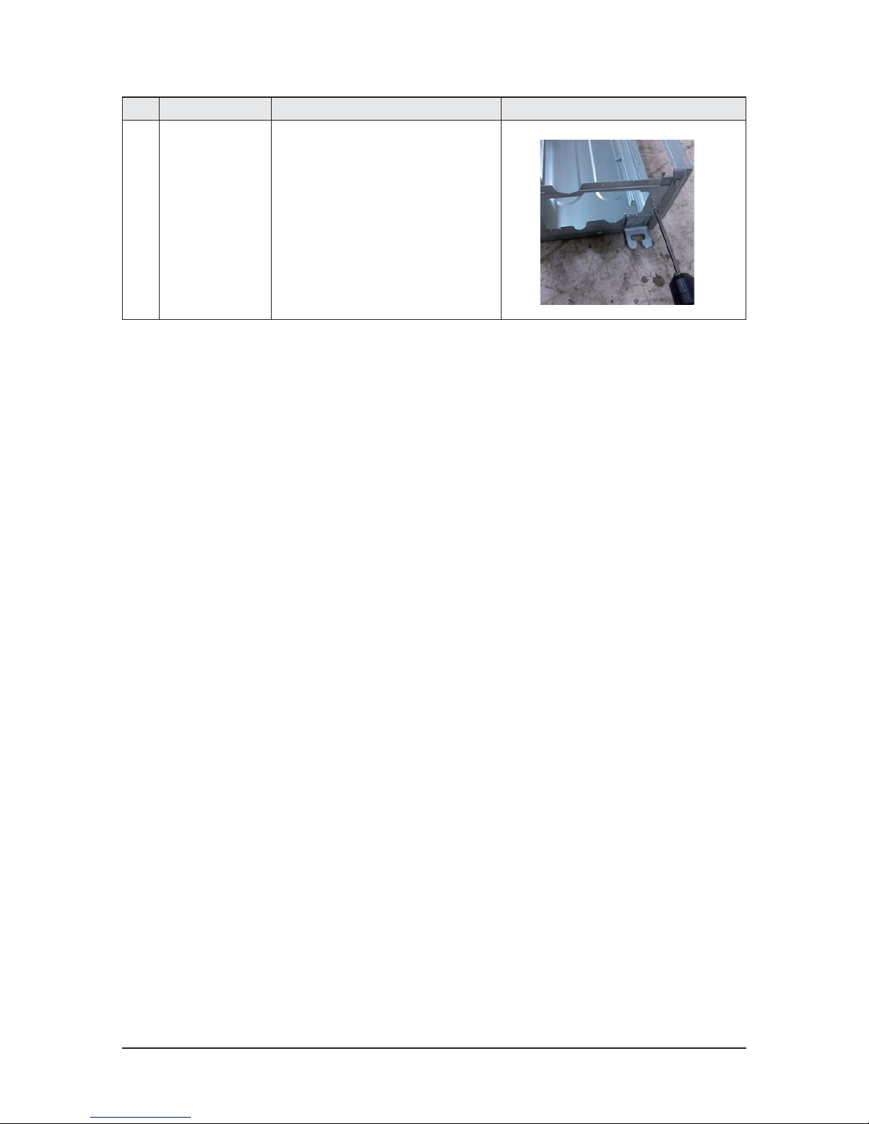
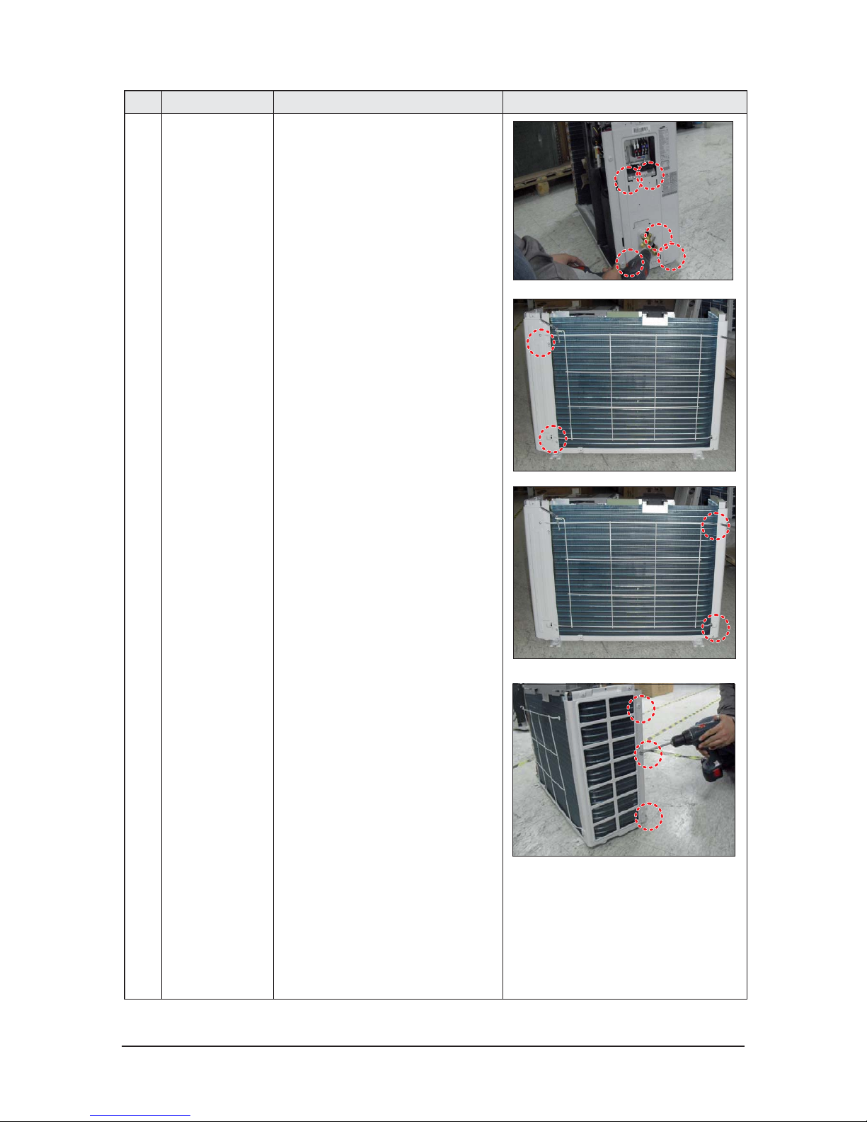
No Parts Procedure Remark
common work 4) loosen 7 screws to disassemble the cabi-
right ,and detach it.
5) loosen 2 screws to disassemble steel-bar.
6) loosen 3 screws to disassemble cabi-left.
Samsung Electronics 3-15
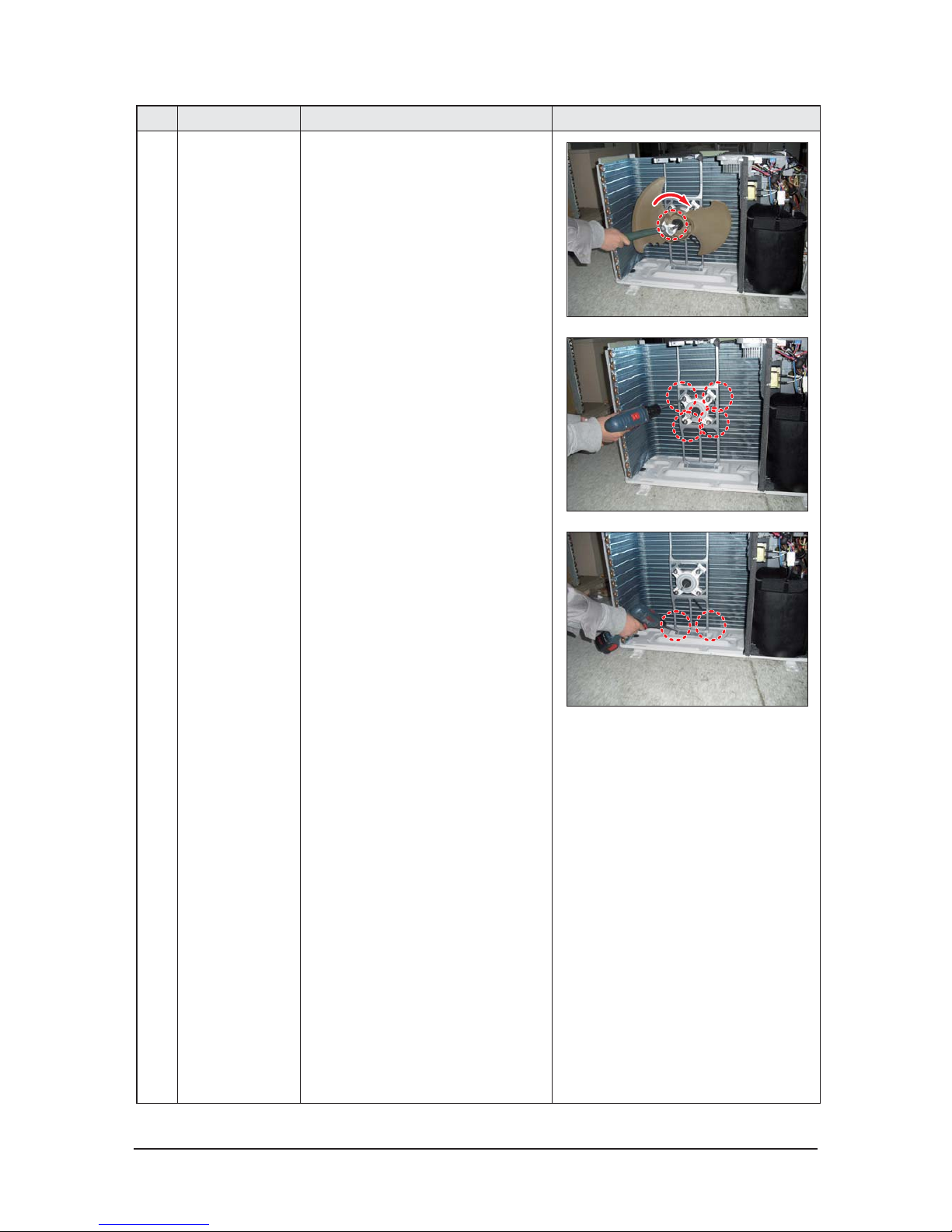
No Parts Procedure Remark
2 fan&motor 1) loosen 1 screw as indication and detached
the fan.
2) loosen 4 pcs motor screws and disconnect
the wire betwwen assy control out and motor.
3) loosen 2 pcs bracket-motor screw and
detach it.
3-16 Samsung Electronics
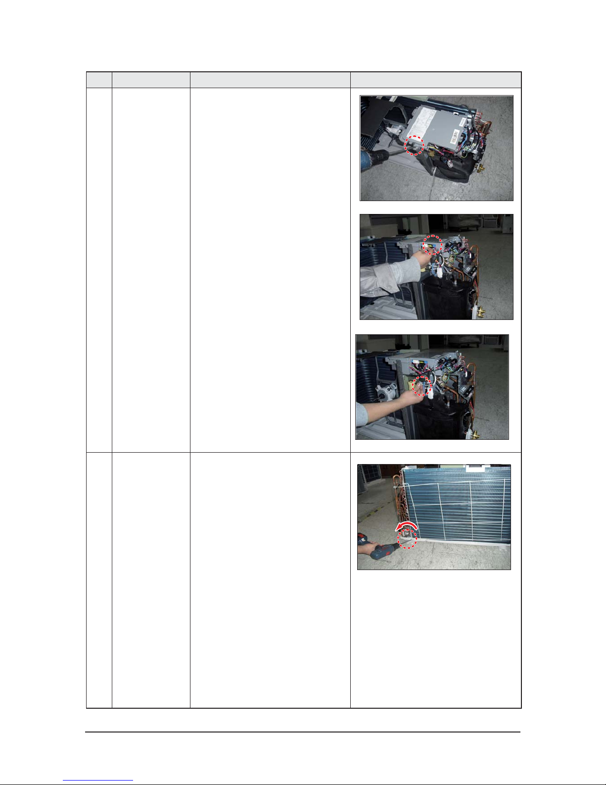
No Parts Procedure Remark
3 assy control out 1) lossen fixing 1 screw from cover -control
2) detach several connections from assy control out, take out assy control out.
4 Heat exchanger 1) Release the refrigerant at first
2) Looosen fixing screw on both side.
3) disaessembly the pipes in both inlet and
outlet with welding torch.
4) detach the heat exchanger.
Samsung Electronics 3-17
No Parts Procedure Remark
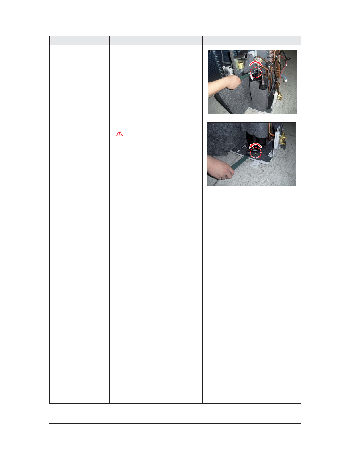
5 compressor 1) disconnect the compressor lead wire .
2)disassembly the felt comp sound.
loosen the 3 bolts at the bottom .
CAUTION
When removing the compressor,
Heat Exchanger, and Pipe, purge the
Coolant inside the Compressor completely and remove the pipe with a welding
flame.
 Loading...