

Samsung AC026FBJDEH, AC052FBJDEH, AC026FCADEH, AC035FCADEH, RC052DHXEA Service Manual
...
Refer to the service manual in the GSPN(see the rear cover) for the more information.
AIR CONDITIONER CONTENTS
SYSTEM AIR CONDITIONER
1. Precautions
2. Product Specifications
3. Disassembly and Reassembly
4. Troubleshooting
5. PCB Diagram
6. Wiring Diagram
7. Schematic Diagram
8. Reference Sheet
AC026FBJDEH/EU
AC035FBJDEH/EU
AC052FBJDEH/EU
AC026FBJDEH/EU
AC035FBJDEH/EU
AC052FBJDEH/EU
AC026FCADEH/EU
AC035FCADEH/EU
AC052FCADEH/EU
BASIC MODEL : JH052EAV1 / RC052DHXEA
MODEL : AC026FBJDEH / AC026FCADEH
AC035FBJDEH / AC035FCADEH
AC052FBJDEH / AC052FCADEH
MODEL CODE :
AC026FBJDEH / EU / AC026FCADEH / EU
AC035FBJDEH / EU / AC035FCADEH/ EU
AC052FBJDEH/ EU / AC052FCADEH/ EU

Contents
11. Precautions
........................................................................................................................................
1-1
1-1 Precautions for the Service
..............................................................................................................
1-1
1-2 Precautions related to static electricity and PL
............................................................................
1-1
1-3 Precautions related to product safety
...........................................................................................
1-2
1-4 Other precautions
..............................................................................................................................
1-2
12. Product Specifications
...............................................................................................................
2-1
2-1 The Feature of Product
.....................................................................................................................
2-1
2-2 Product Specifications
......................................................................................................................
2-2
2-3 Accessories
..........................................................................................................................................
2-4
13. Disassembly and Reassembly
...............................................................................................
3-1
3-1 Indoor Unit
.........................................................................................................................................
3-2
3-2 Outdoor Unit
.....................................................................................................................................
3-7
14. Troubleshooting
............................................................................................................................
4-1
4-1 Setting an indoor unit address and installation option
............................................................
4-1
4-1-1 The procedure of setting option
.........................................................................................
4-1
4-1-2 The procedure of setting option
.........................................................................................
4-2
4-1-3 Setting an indoor unit address (MAIN/RMC)
.....................................................................
4-4
4-1-4 Setting an indoor unit installation option (suitable for the condition of(each installation location)
....................
4-5
4-1-5 Changing a particular option
...............................................................................................
4-7
4-1-6 Option code for each model
................................................................................................
4-8
4-2 Items to check before diagnostics
.................................................................................................
4-9
4-2-1 Four directions cassette type
...............................................................................................
4-9
4-2-2 Test run mode and View mode
...........................................................................................
4-11
4-2-3 ECO mode(Power save)
.........................................................................................................
4-12
4-2-4 Troubleshooting for outdoor unit
.......................................................................................
4-13
4-2-5 Wired remote controller
.......................................................................................................
4-14
4-3 Troubleshooting by symptoms
......................................................................................................
4-15
4-3-1 Indoor temperature sensor (open/short)
..........................................................................
4-15
4-3-2 Indoor heat exchanger temperature sensor (open/short)
.............................................
4-16
4-3-3 Indoor FAN error
.....................................................................................................................
4-17
4-3-4 Communication error after finishing Tracking
.................................................................
4-18
4-3-5 Indoor unit float sensor error
...............................................................................................
4-19
4-3-6 EEPROM circuit failure
...........................................................................................................
4-20
4-3-7 Outdoor unit is not powered on
.........................................................................................
4-21

4-4 Troubleshooting by symptoms ............................................................................................................................... 4-23
4-4-1 Communication error
..........................................................................................................
4-23
4-4-2 Outdoor temperature sensor error
....................................................................................
4-24
4-4-3 Outdoor Coil temperature sensor error
..............................................................................................
4-26
4-4-4 Outdoor Discharge temperature sensor error
.................................................................
4-28
4-4-5 Outdoor Discharge over temperature error
.....................................................................
4-30
4-4-6 Outdoor Fan motor error .................................................................................................................... 4-31
4-4-7 Compressor starting error .................................................................................................................. 4-32
4-4-8 Compressor wire missing error/rotation error .......................................................................... 4-33
4-4-9 O.C(Over Current) error ....................................................................................................................... 4-34
4-4-10 DC_link voltage sensor error .......................................................................................................... 4-35
4-4-11 DC_link voltage under/over error, Over voltage protection error/PFC over load ..... 4-36
4-4-12 DC_link voltage sensor error........................................................................................................... 4-37
4-4-13 Current sensor error/Input current sensor error .................................................................... 4-38
4-4-14 Heatsink sensor error/Heatsink over heat ................................................................................. 4-39
4-4-15 Comp Vlimit error/Comp current limit error ............................................................................ 4-40
4-4-16 EEPROM error/OTP error .................................................................................................................. 4-41
4-4-17 AC zero cross signal error ................................................................................................................. 4-42
4-4-18 Operation condition secession error............................................................................................ 4-43
4-4-19 Capacity miss match error ............................................................................................................... 4-44
4-4-20 Gas leak error ........................................................................................................................................ 4-45
4-4-21 MDS Error Flow chart ........................................................................................................................ 4-46
15. PCB Diagram
.....................................................................................................................................
5-1
5-1 PCB Diagram
......................................................................................................................................
5-1
5-1-1 Indoor Unit
..............................................................................................................................
5-1
5-1-2 Display PCB
...............................................................................................................................
5-2
5-1-3 DAMPER PBA
...........................................................................................................................
5-2
5-1-4 Outdoor Unit PCB
...................................................................................................................
5-3
16. Wiring Diagram
..............................................................................................................................
6-1
6-1 Indoor Unit
........................................................................................................................................
6-1
6-2 Outdoor Unit
....................................................................................................................................
6-2
17. Schematic Diagram
......................................................................................................................
7-1
7-1 Indoor Unit
...................................................................................................................................
7-1
7-2 Outdoor Unit
................................................................................................................................
7-4
8. Reference Sheet
.............................................................................................................................
8-1
8-1 Index for Model Name
......................................................................................................................
8-1
8-2 Refrigerating Cycle Diagram
............................................................................................................
8-2
8-3 Pressure Graph
...................................................................................................................................
8-3

Samsung Electronics 1-1
1. Precautions
1-1 Precautions for the Service
UUse the standard parts when replacing the electric parts.
– Confirm the model name, rated voltage, rated current of the electric parts.
UWhen repairing the equipment, connection of the harness parts must be firm and solid.
– A loose connection may cause noise or other malfunction.
UWhen assembling and disassembling the equipment while it is laid down, lay it on soft cloth.
– Otherwise it may scratch the back of the exterior of the product.
URemove dust or dirt completely from the housing block, wiring block and service parts during repair.
– This helps prevent the danger of fire caused by tracking or short circuit.
UFasten the valve caps of service valves and charging valves of outdoor unit as much as possible using adjustable wrenches.
UCheck the status of the components’ assembly after repair service.
– The status must be the same as before the repair service.
1-2 Precautions related to static electricity and PL
U The PCB power supply block is susceptible to static electricity. Therefore, care must be taken during repair or measuring
while the power is on.
– Wear insulation gloves for PCB repair or measuring.
U Check whether the installation location is at least two meters away from other electronic products such as TV, video, or
audio.
– Otherwise, the video quality might be degraded or noise might be generated.
U Do not let end users repair the products themselves.
– Unauthorized disassembly might cause electric shock or fire.

1-2 Samsung Electronics
1-3 Precautions related to product safety
U Do not pull the power cord and do not touch the power plug or aux power switch with wet hands.
– It might cause electric shock or fire.
U A damaged power line or power plug must be replaced to prevent danger.
U Do not bend the power cable with excessive force, and do not place a heavy weight on the case as it might damage the
cable.
– It might cause electric shock or fire.
U Do not use multiple electric outlets.
– This might cause electric shock or fire.
U Connect the ground terminal when necessary.
– You must connect the ground terminal if you determine that there is a danger of electric leakage due to moisture or water.
U Unplug the power cable or turn off the auxiliary power switch for electric part replacement and repair service.
– Otherwise it might cause electric shock.
U Instruct end users to separate the batteries from the remote controllers and store them separately when the product is not
used for long time.
– Otherwise leakage from the dry cell may cause problems with the remote controller.
1-4 Other precautions
U The pipes should have no leaks during installation, and the compressor must be stopped before removing connecting
pipes for pump down work. Operating the compressor while the service valve is open and coolant pipe is not properly
connected may cause explosion or injury due to abnormal high pressure created inside the coolant cycle as the air can be
absorbed through the pipe.
U Pump Down work procedure (When uninstalling the product)
– Turn on the air conditioner, select cooling operation, and run the compressor for more than three minutes.
– Release the high pressure and low pressure valve caps.
– Close the high pressure valve completely using an L-wrench
– After about two minutes, close the low pressure valve completely.
– Stop running the air conditioner.
– Separate the connecting pipe.
Samsung Electronics 2-1
2. Product Specifications
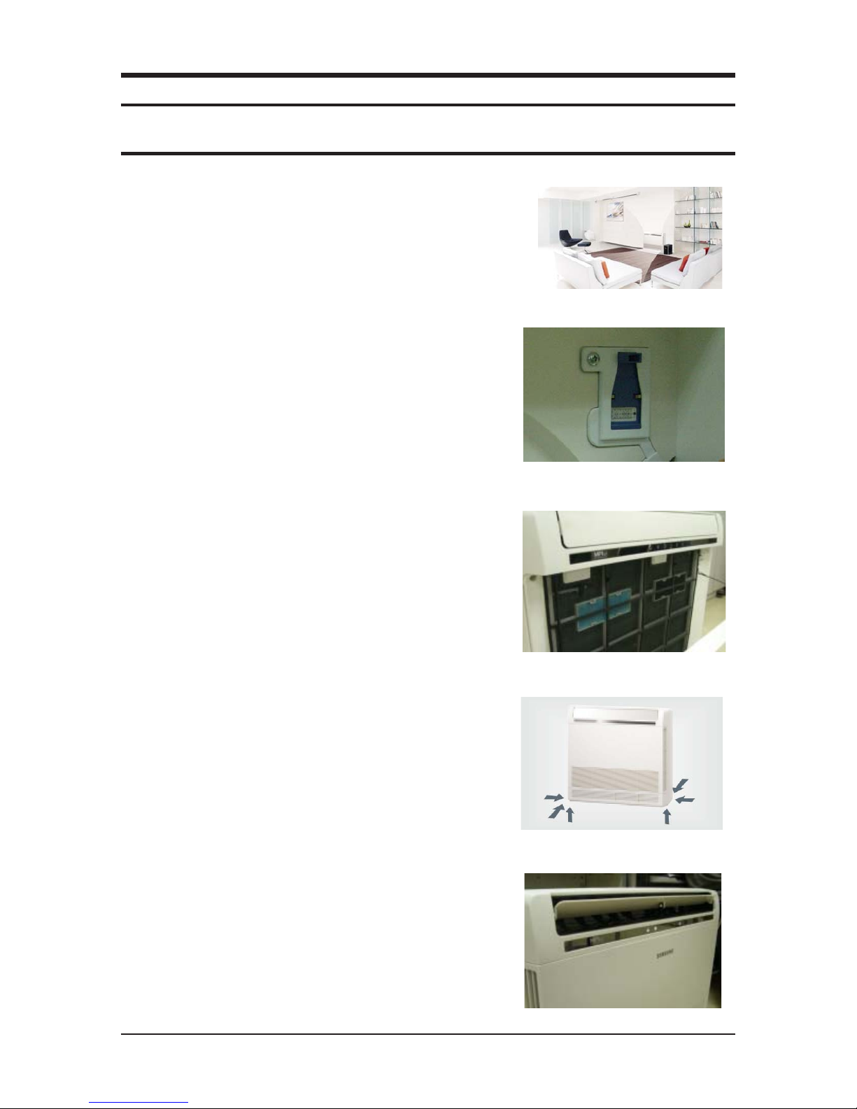
2-1 The Feature of Product
N What is a Console type Air Conditioner?
Floor standing type Air Conditioner, Powerful on floor heating & cooling.
N VIRUS DOCTOR Zone (Air cleaning solution)
Samsung’s Micro Plasma Ion Zone is a technology that generates
activated hydrogen and oxygen ions, which exterminates viruses
and allergy-causing microbes in the air by neutralizing them and
turning into water.
N Special Filter
Allergy Filter, Deodorizing Filter and Anti-bacteria
Filter will make air so pure.
N Flexible Pipe Installation
Anywhere it can be installed by 6way piping.
N Elegance Design
Slim Design(199mm), Clean Front Panel, Luxurious Wide Display
Mirror & Lamp
2-2 Samsung Electronics
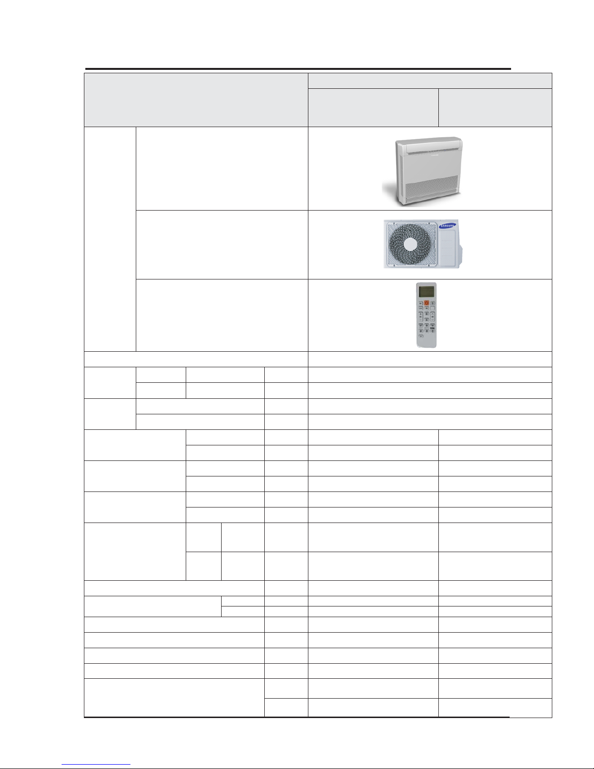
2-2 Product Specifications
Item
Model Name
AC026FBJDEH/EU
AC026FBADEH/EU
AC035FBJDEH/EU
AC035FBADEH/EU
Design
Indoor Unit
Outdoor Unit
Remote Control
Power specifications Single phase, 220~240V, 50Hz
Size
Indoor
W×H×D mm 720X620X199
Outdoor W×H×D mm 790X548X285
Weight
Indoor Unit kg 15.2
Outdoor Unit kg 33
Capacity
Cooling w 2600 3500
Heating w 3500 4000
Power
consumption
Cooling w 810 1290
Heating w 1060 1330
Operation current
Cooling A 4 6
Heating A 5 6.2
Sound Power
Indoor
In case of
strongest air
blow
'dBa 53 55
Outdoor
In case of
strongest air
blow
'dBa 61 61
Refrigerant(R410A) g 950 950
Connecting Pipe
Liquid Ø 1/4" 1/4"
Gas Ø 3/8" 3/8"
Additional Refrigerant(R410A) g/m Chargeless Chargeless
Standard m 5 5
Extension length(Total) m 20 20
Extension length(Elevation) m 15 15
Option Code
Product
Option
018077-1760B6-271A23-370210 018077-1760D8-272328-370210
Installation
Option
020000-100000-200000-300000 020000-100000-200000-300000
Samsung Electronics 2-3
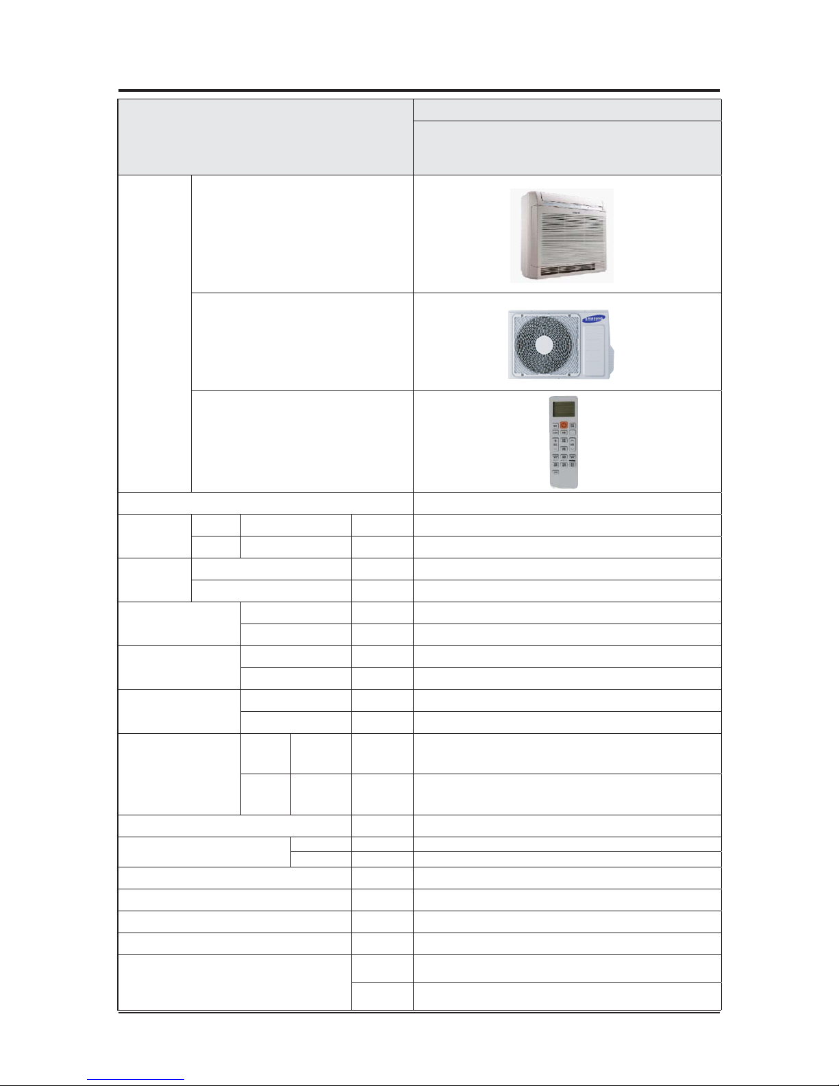
Item
Model Name
AC052FBJDEH/EU
AC052FBADEH/EU
Design
Indoor Unit
Outdoor Unit
Remote Control
wPower specifications Single phase, 220~240V, 50Hz
Size
Indoor W×H×D mm 720X620X199
Outdoor W×H×D mm 790X548X285
Weight
Indoor Unit kg 15.2
Outdoor Unit kg 38.5
Capacity
Cooling w 5000
Heating w 5600
Power
consumption
Cooling w 1780
Heating w 1920
Operation current
Cooling A 8
Heating A 8.7
Sound Power
Indoor
In case of
strongest air
blow
'dBa 60
Outdoor
In case of
strongest air
blow
'dBa 64
Refrigerant(R410A) g 1400
Connecting Pipe
Liquid Ø 1/4"
Gas Ø 1/2"
Additional Refrigerant(R410A) g/m 10
Standard m 5
Extension length(Total) m 30
Extension length(Elevation) m 20
Option Code
Product
Option
018077-1760F9-273438-370210
Installation
Option
020000-100000-200000-300000
Product Specifications (cont.)
2-4 Samsung Electronics
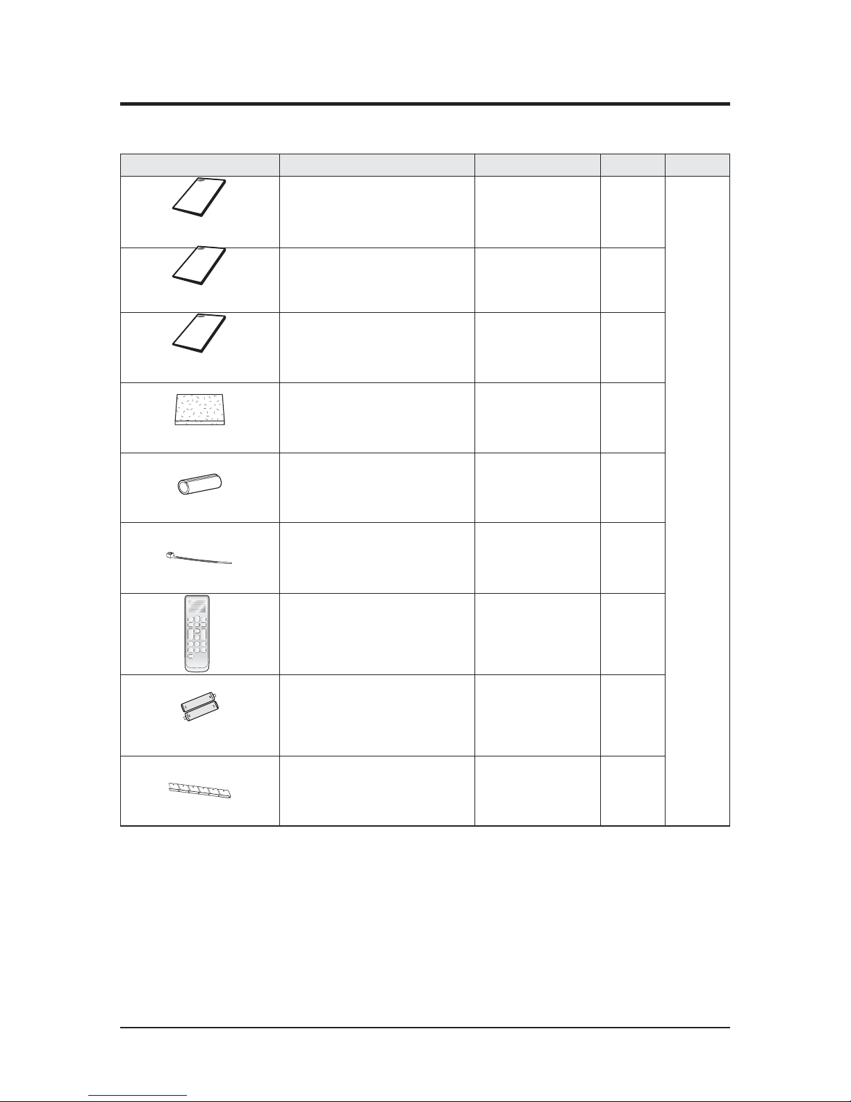
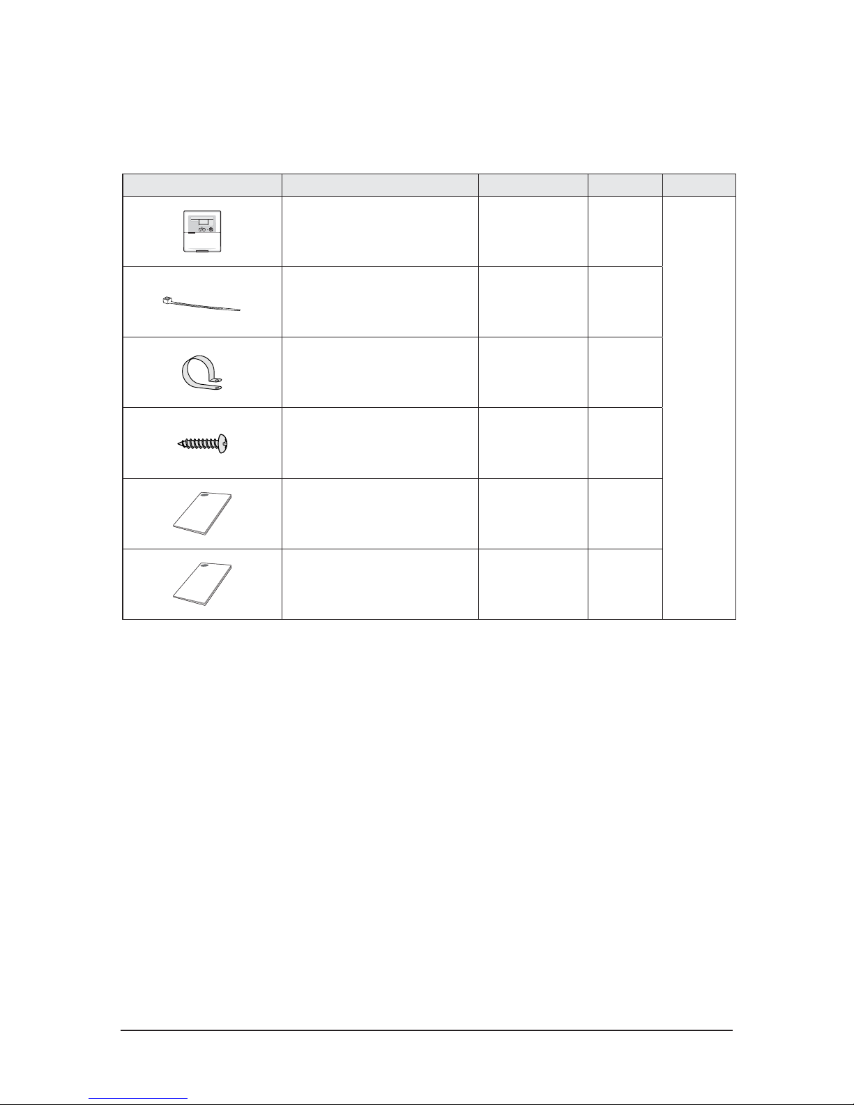
2-3 Product Accessories and Option accessories
Item Descriptions Code-No. Q'TY Remark
User’s
manual
DB68-03441A 1
Basic/
Indoor
Installation
manual
DB68-03439A 1
Installation
guide
DB98-29840A 1
Insulation
install out
B62-05580V 1
Insulation install SVC
DB62-05691C 1
Cable-tie
DB65-10088C 4
Wireless remote control DB93-11115N 1
Battery
4301-000121 2
Bracket
hanger
DB61-03708A 1
NProduct Accessories
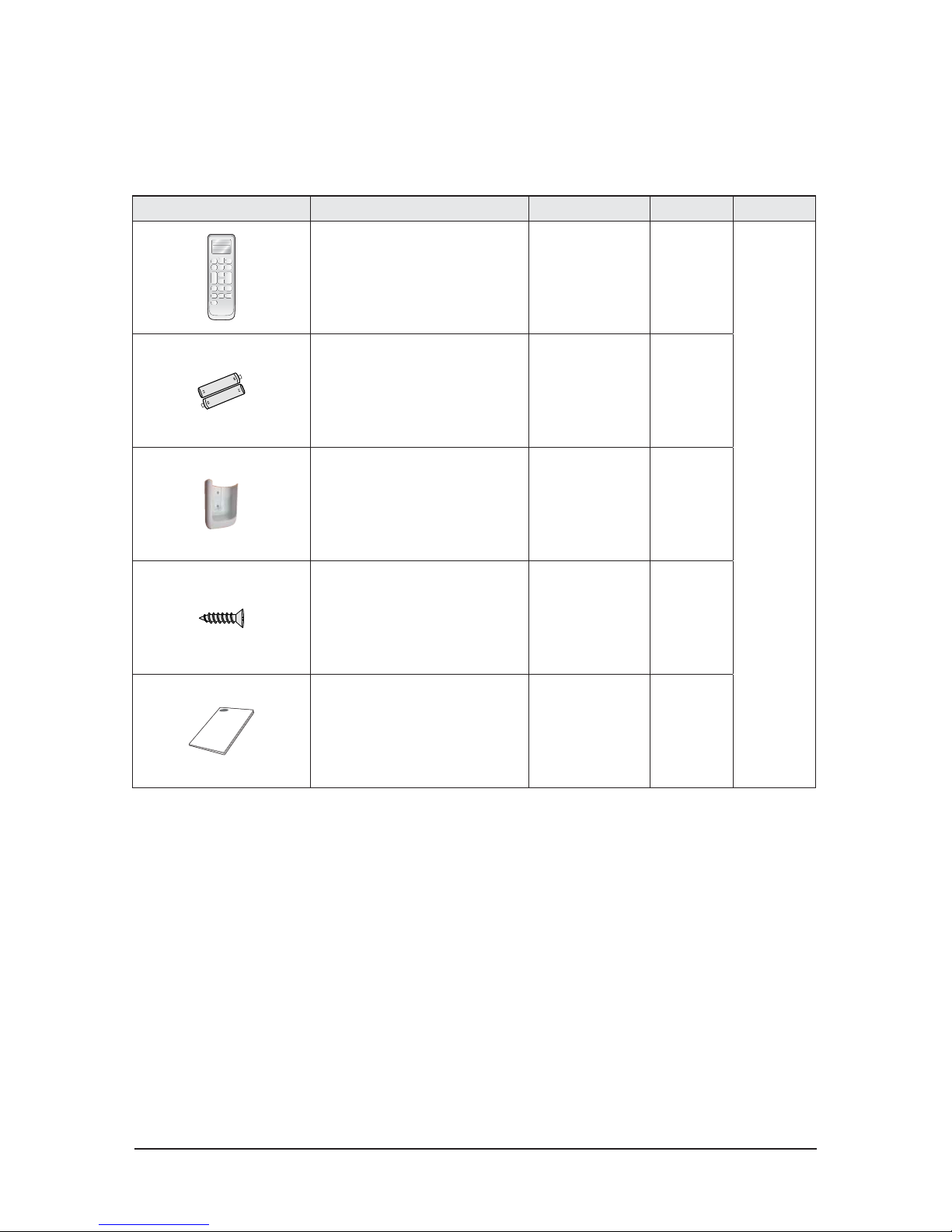
Samsung Electronics 2-5
Item Descriptions Code-No. Q'TY Remark
Wireless remote controller DB93-11115N 1
Optional
Batteries for remote controller
(specification: "AAA" type)
DB47-90024A 2
Remote controller holder DB61-04899A 1
M4×16 screw 6002-000581 2
User’s manual DB98-33129A 1
N
Option
accessories
U Wireless remote controller (MR-DH00) [Code No. : DB97-17546B]
2-6 Samsung Electronics
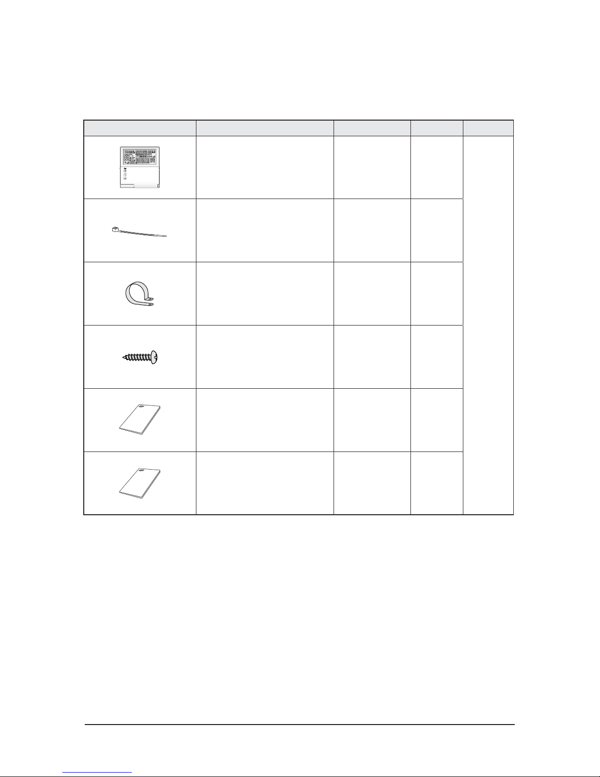
Option accessories (cont.)
U Wired remote controller (MWR-WE10) [Code No. : DB97-17002B]
Item Descriptions Code-No. Q'TY Remark
Wired remote controller DB93-11251B 1
Optional
Cable tie DB65-10088B 2
Cable clamp DB65-10074E 3
M4×16 Screw 6002-000474 5
User’s manual DB98-32810A 1
Installation guide DB98-32811A 1
Samsung Electronics 2-7
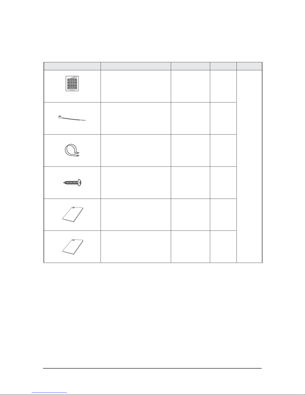
Option accessories (cont.)
U Central controller (MCM-A202D) [Code No. : DB97-18602B]
Item Descriptions Code-No. Q'TY Remark
Central controller DB93-03425N 1
Optional
Cable tie DB65-10088B 2
Cable clamp DB65-10074E 5
M4 X 16 Screw 6002-000474 7
User’s manual DB98-33437A 1
Installation guide DB98-33434A 1
2-8 Samsung Electronics
Option accessories (cont.)
U Function controller (MCM-A100) [Code No. : DB97-01077A]
Item Descriptions Code-No. Q'TY Remark
Function controller DB93-00757G 1
Optional
Cable tie DB65-10088B 2
Cable clamp DB65-10074E 6
M4×16 Screw 6002-000474 7
User’s manual DB98-27317A 1
Installation guide DB98-27315A 1
* PC control and DMS cannot be used when using the function controller
Samsung Electronics 2-9
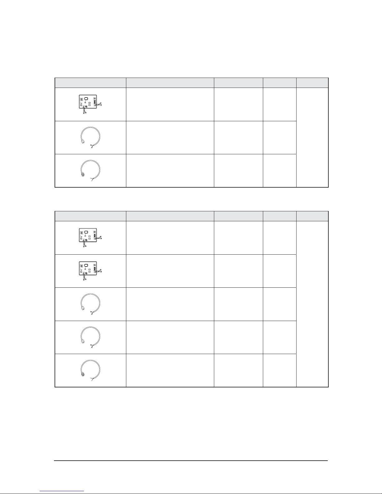
Option accessories (cont.)
U Relay (MIM-B13D) [Code No. : DB97-18519A]
U Relay (MIM-B13E) [Code No. : DB97-04416J)
Item Descriptions Code-No. Q'TY Remark
Relay DB93-12203A 1
Optional
Relay power cable
(300mm)
DB39-00378B 1
Relay communication cable
(300mm)
DB39-00253B 1
Item Descriptions Code-No. Q'TY Remark
Relay DB93-03568D 1
Optional
Relay sub DB93-03590B 1
Relay power cable
(1,000mm)
DB93-07895A 1
Relay power cable
(1,000mm)
DB93-07895B 1
Relay communication cable
(100mm)
DB93-12164A 1

2-10 Samsung Electronics
UFilter accessory
Item Descriptions Code-No. Remark
Dust filter DB63-02739A
Basic/
Water wash
Samsung Electronics 3-1
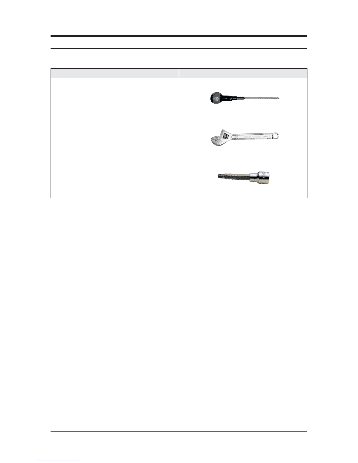
Item Remarks
+SCREW DRIVER
Adjustable Wrench
(8mm, 10mm, 13mm)
M6, M8 Hex Wrench
NNecessary Tools
3. Disassembly and Reassembly
3-2 Samsung Electronics
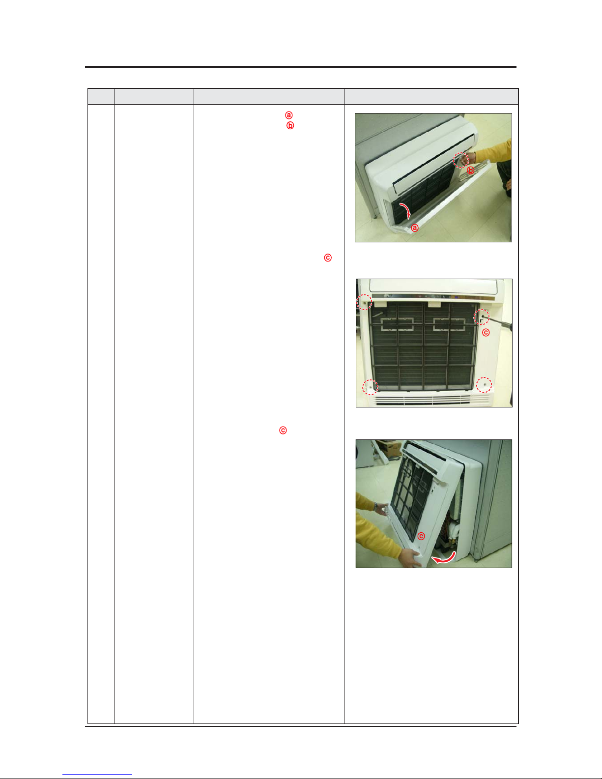
3-1 Indoor unit
No Parts Procedure Remark
1 Cabi Parts 1) Open the Panel Front(ͽ).
Remove the Clip Wire(
;).
2) Release 4 screws on the Body Front(
Ϳ).
3) Open the Body Front(
Ϳ) by pulling
from bottom of the part.
ͽ
;
Ϳ
Ϳ
NAC026FBJDEH/EU/ AC035FBJDEH/EU/ AC052FBJDEH/EU
Samsung Electronics 3-3
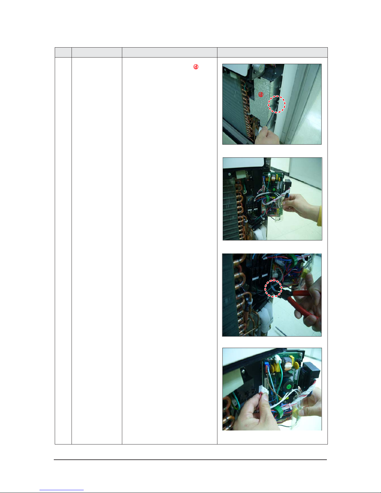
No Parts Procedure Remark
Electrical Parts 1) Open the cover of Control Box).
2) Pull the PBA out along the slide guide.
3) Cut the Cable tie.
4) Pull all wires out from the PBA.
3-4 Samsung Electronics
No Parts Procedure Remark
5) Release the 2 screws.
(one is top of the C-Box, the other is left of it)
6) Release 2 Hold Wires and
pull all wires out from it .
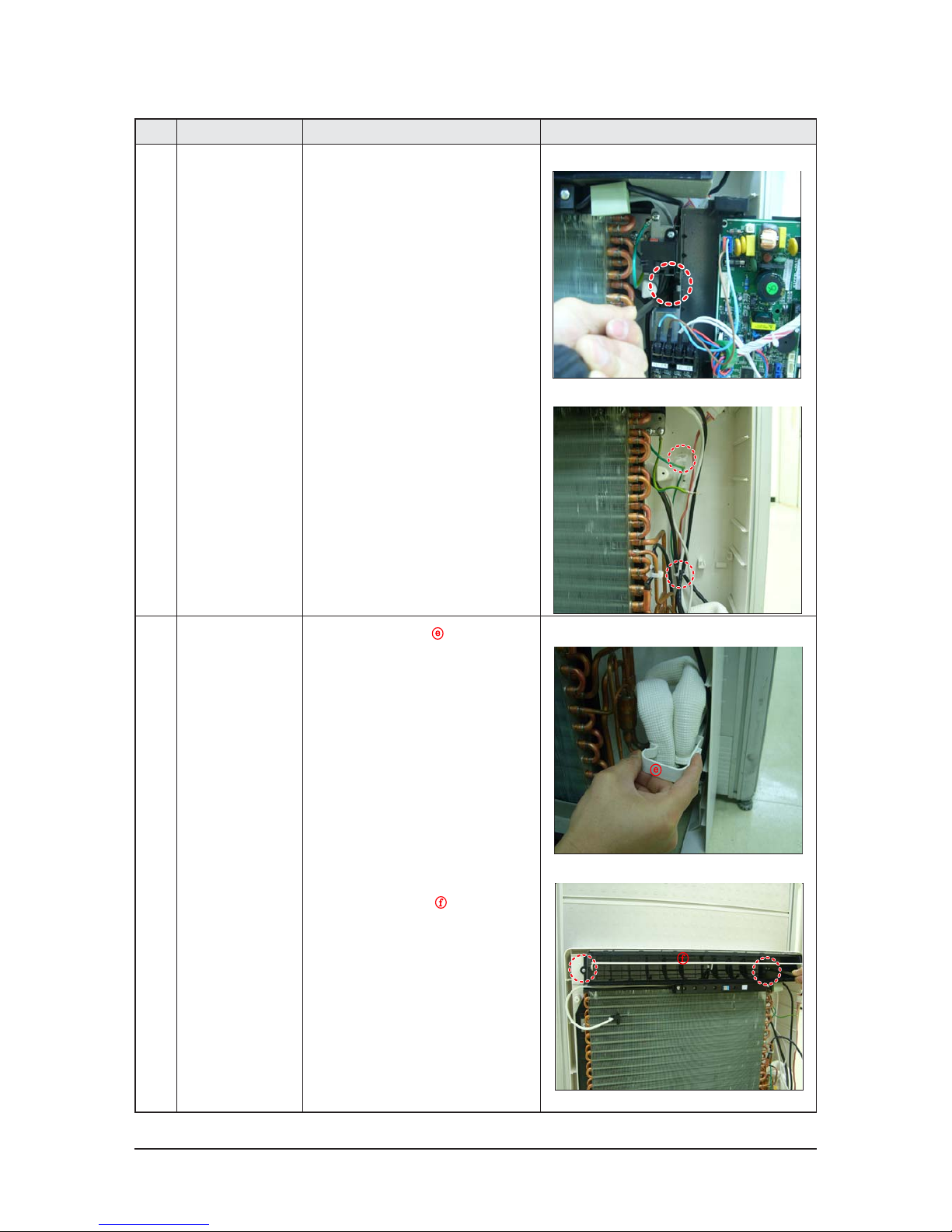
3
Blowing
&
Evap Part
1) Pull the Bracket Pipe( )out.
2) Release 2 screws and
pull Top Discharge Kit(
) out.
Samsung Electronics 3-5
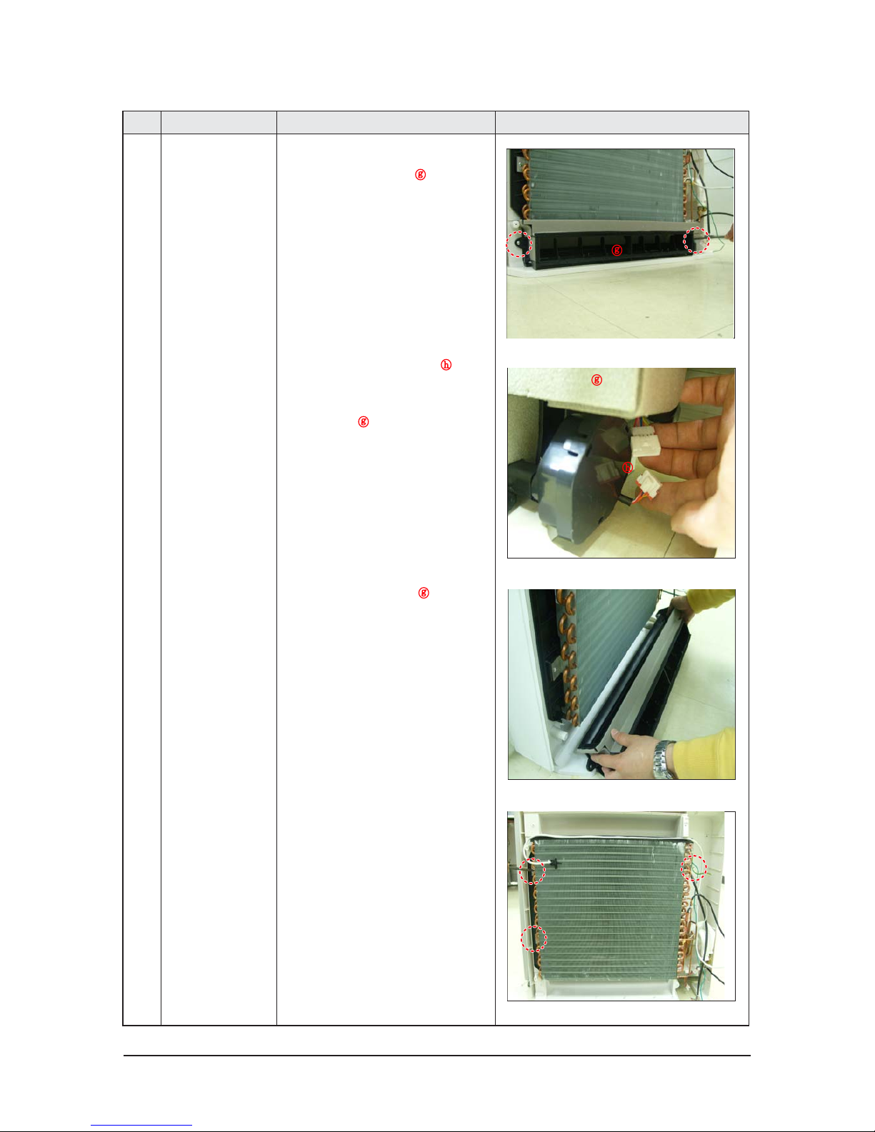
No Parts Procedure Remark
3) Release 2 screws and
pull Bottom Discharge Kit(
) out.
4) Disconect the Step Motor wire(
΄) from
the conect wire .
This part is right side of the Bottom
Discharge Kit(
).
5) Pull Bottom Discharge Kit(
) Out
from the bottom of it.
6) Release 3 screws and pull the Evap out
from top to bottom direction.
΄
Ê
3-6 Samsung Electronics
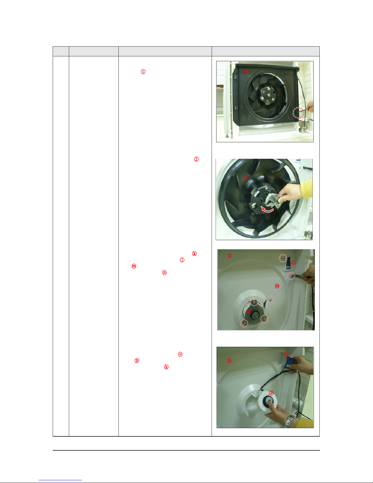
No Parts Procedure Remark
4 Fan Part 1)
Release 1 screw and pull the Bell
Mouth (
΅
) out.
2) Release the Nut and pull Fan Turbo(
Ά)out.
3) Release 6 screw on the Body Back(
·).
Pull the Cap VIRUS DOCTOR(
Έ), Bracket
Wire(
Ή)
and Bracket Motor(
Ί) out.
4) Pull the VIRUS DOCTOR Kit(
) and
Motor(
Ό) out
from the Body Back(
·).
΅
Ά
·
Έ
Ή
Ί
Ό
·
Samsung Electronics 3-7
No Parts Procedure Remark
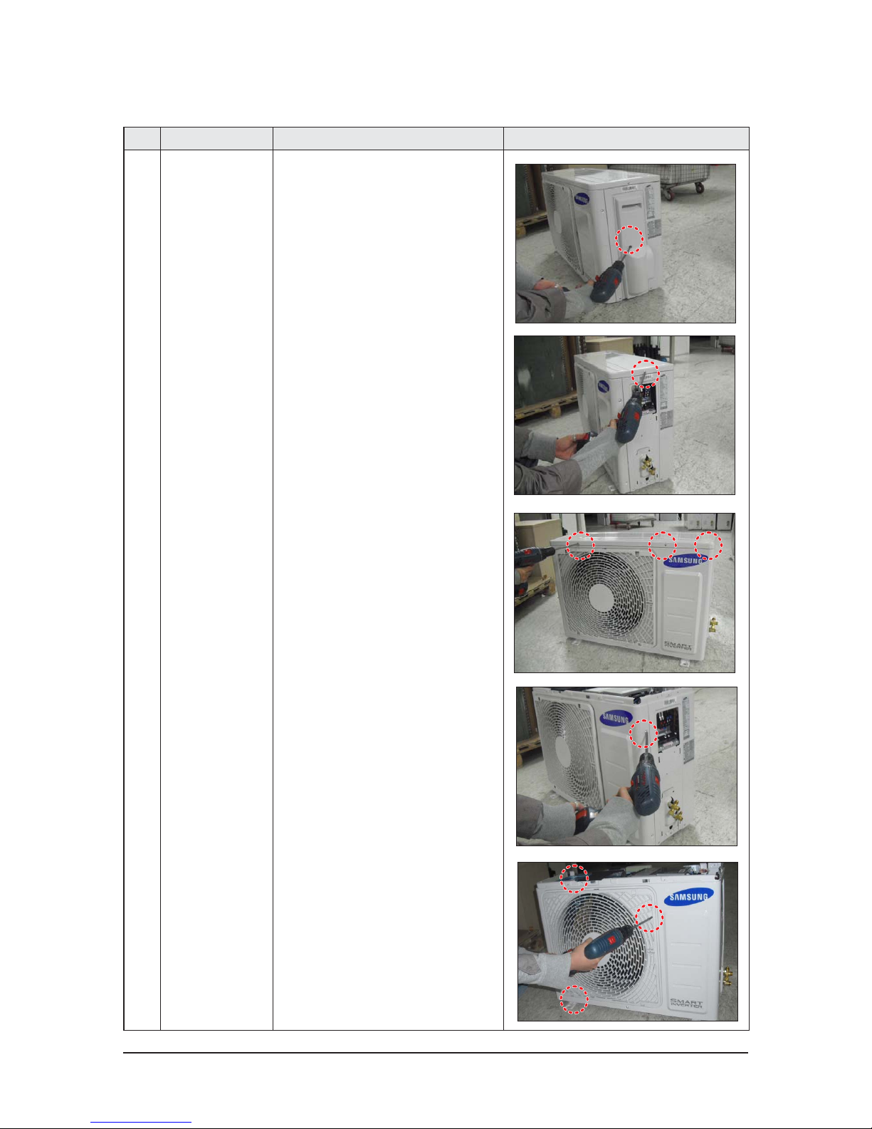
1 common work 1) loosen 1 pcs screw of cover control,and
detach it.
2) loosen 5 pcs screws on both right and
left cabniet side edges and to detach the
cover-top
3) Loosen 7 screwsfixed to disassemble
cabi-front , and detach it.
3-2 Outdoor unit
NAC026FCADEH/EU/ AC035FCADEH/EU/ AC052FCADEH/EU
3-8 Samsung Electronics
No Parts Procedure Remark
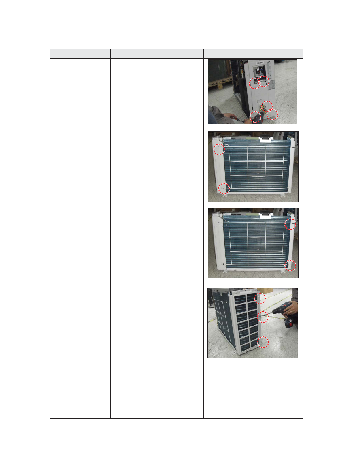
common work 4) loosen 7 screws to disassemble the cabi-
right ,and detach it.
5) loosen 2 screws to disassemble steel-bar.
6) loosen 3 screws to disassemble cabi-left.
Samsung Electronics 3-9
No Parts Procedure Remark
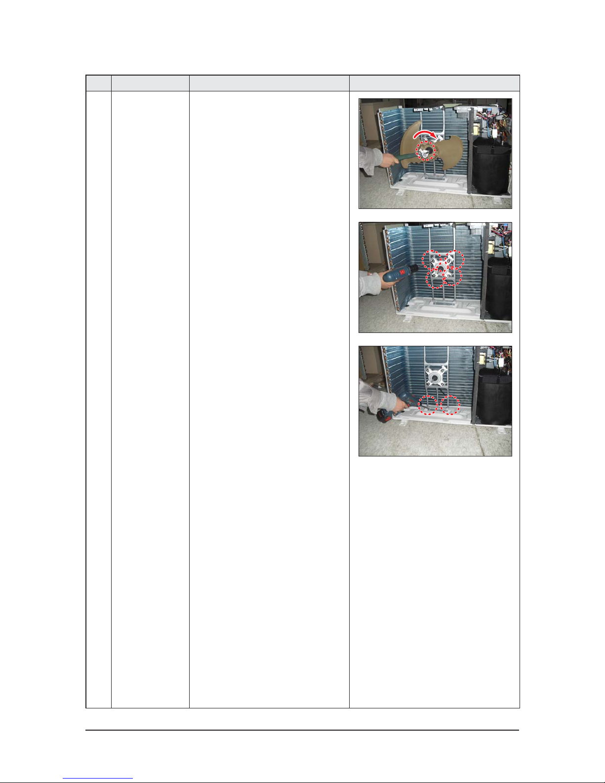
2 fan&motor 1) loosen 1 screw as indication and detached
the fan.
2) loosen 4 pcs motor screws and disconnect
the wire betwwen assy control out and motor.
3) loosen 2 pcs bracket-motor screw and
detach it.
3-10 Samsung Electronics
No Parts Procedure Remark
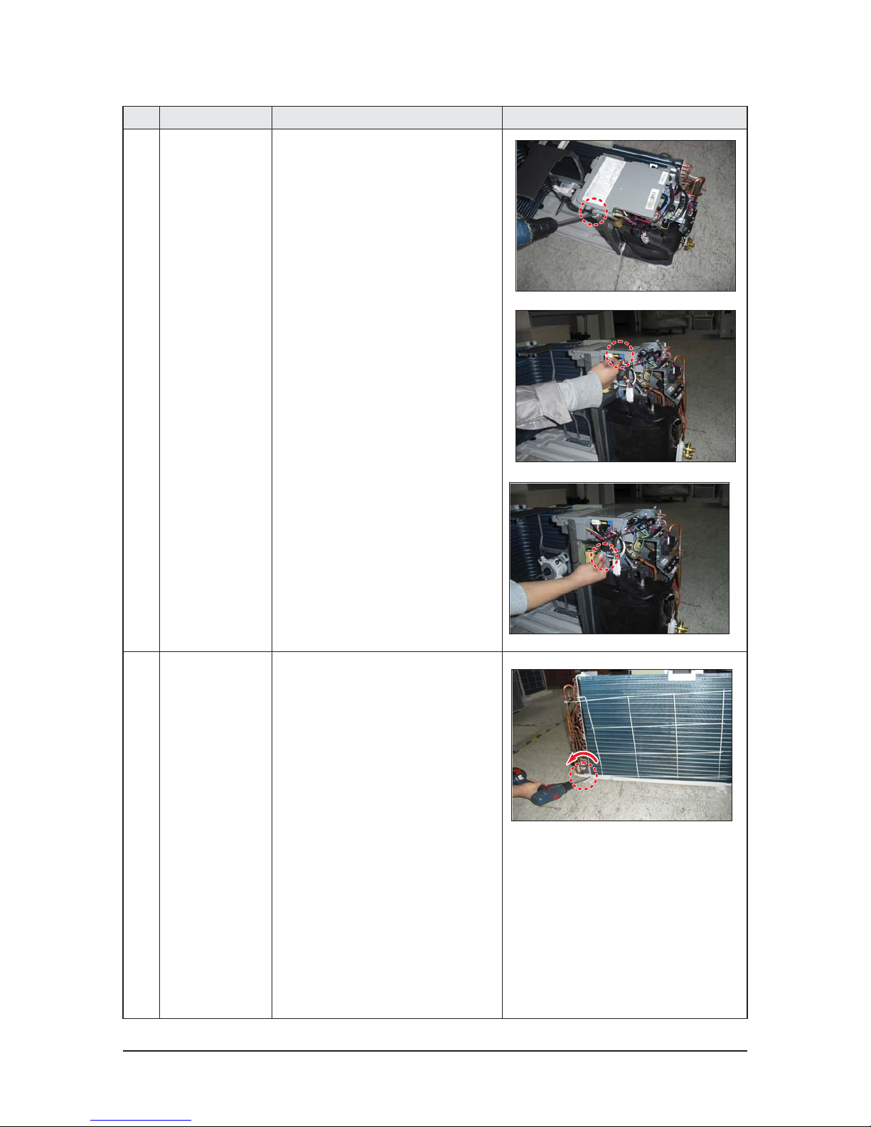
3 assy control out 1) lossen fixing 1 screw from cover -control
2) detach several connections from assy con-
trol out, take out assy control out.
4 Heat exchanger 1) Release the refrigerant at first
2) Looosen fixing screw on both side.
3) disaessembly the pipes in both inlet and
outlet with welding torch.
4) detach the heat exchanger.
Samsung Electronics 3-11
No Parts Procedure Remark
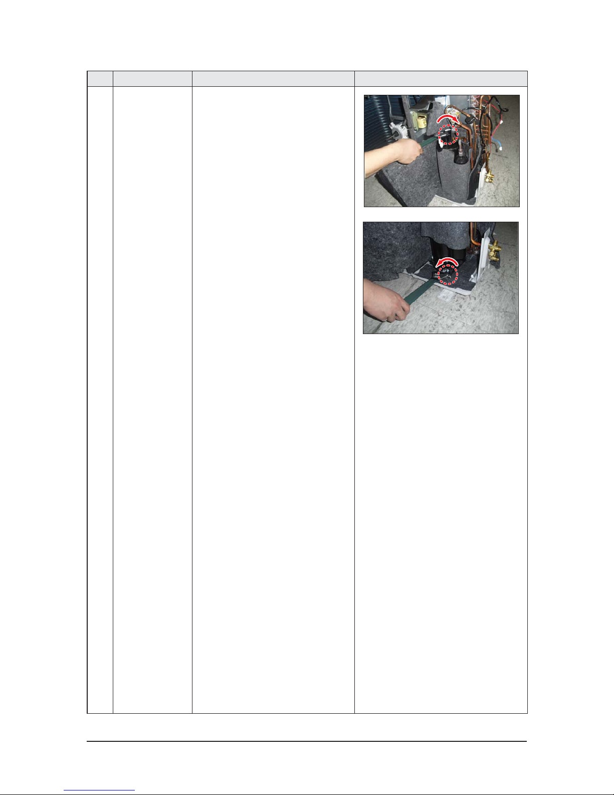
5 compressor 1) disconnect the compressor lead wire .
2)disassembly the felt comp sound.
loosen the 3 bolts at the bottom of
4-1 Samsung Electronics
4. Troubleshooting
4-1 Setting an indoor unit address and installation option
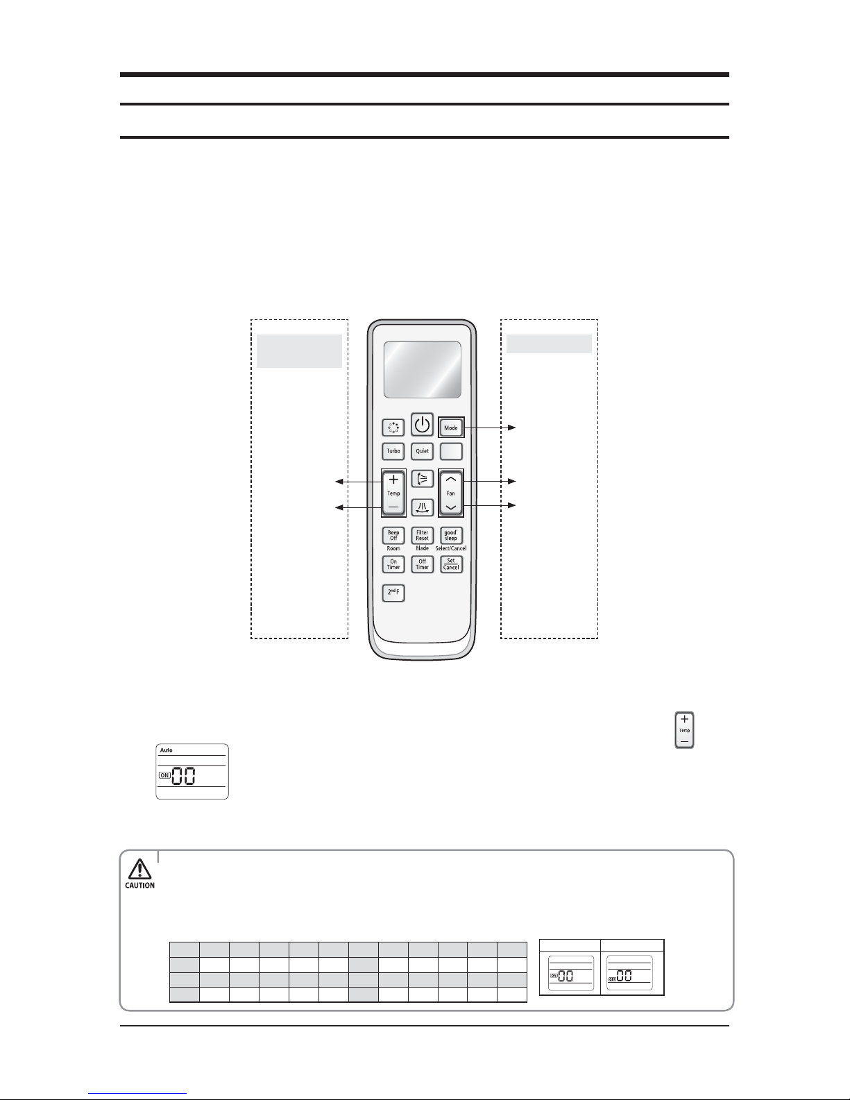
4-1-1 The procedure of setting option
High Temp Button
High Fan Button
Mode change
Low Temp Button
Low Fan Button
Entering mode for
setting option
Option setting mode
▶
Set the indoor unit address and installation option with remote controller option.
Set the each option separately since you cannot set the ADDRESS setting and indoor unit installation setting option at the
same time.You need to set twice when setting indoor unit address and installation option.
▶
Please use the proper wireless remocon which can set 24 digit option code. Following is the instructions of setting option
code with wireless remocon of MR-DH00. (MR-AH01 can be used for operating but cannot be used for setting the installation
option because only 12 digit option setting is available.
▶
Please refer to the wired remocon installation manual for setting with the wired remocon.
Step 1. Entering mode to set option
1. Remove batteries from the remote controller.
2. Insert batteries and enter the option setting mode while pressing High Temp button and Low Temp button.
3. Check if you have entered the option setting status.
Step 2. The procedure of option setting
After entering the option setting status, select the option as listed below.
Option setting is available from SEG1 to SEG 24
t 4&(4&(4&(4&(BSFOPUOFFEUPCFTFUBU.3%)5IFZBSFUIFQBHFPQUJPOTXIJDIXFSFVTFEBUUIF
previous other remocons.
t 4FUUIFFBDICJUPQUJPODPEFJOPSEFSFYDFQUQBHFPQUJPOT
For example : SEG2, 3 SEG4, 5 SEG6, 8 SEG9, 10 SEG11, 12 SEG 14, 15 SEG 16, 17 SEG 18, 20
SEG 21, 22 SEG23, 24.
On(SEG1~12) O(SEG13~24)
SEG1 SEG2 SEG3 SEG4 SEG5 SEG6 SEG7 SEG8 SEG9 SEG10 SEG11 SEG12
0XXXXX1XXXXX
SEG13 SEG14 SEG15 SEG16 SEG17 SEG18 SEG19 SEG20 SEG21 SEG22 SEG23 SEG24
2XXXXX3XXXXX
 Loading...