

Samsung 732NPLUS, 932B, 932BPLUS, 932NPLUS Service Manual
SERVICE
Manual
TFT-LCD Monitor
Fashion Feature
LCD-Monitor
Chassis Model
LS17PEA 732N
732NPLUS
LS19PEB 932B
932BPLUS
LS19PEA 932NPLUS
-Lustrous/Colorful Appearance (Design)
-Integrated UI applied
-Built-in Scaler Sync Separator
-Connectivity :
LS17PEA, LS19PEA - Analog (15p Dsub)
LS19PEB - Analog (15p Dsub),
Dual (24p DVI-D)
-Power Consumption : 17"(34W), 19"(38W)
-DPMS : under 1 W (230Vac)

ii
Copyright
©2006 by Samsung Electronics Co., Ltd.
All rights reserved.
This manual may not, in whole or in part, be copied,
photocopied, reproduced, translated, or converted to
any electronic or machine readable form without prior
written permission of Samsung Electronics Co., Ltd.
LS17PEA/LS19PEA/LS19PEB Service Manual
First edition February 2006.
Printed in Korea.
Trademarks
Samsung is the registered trademark of Samsung
Electronics Co., Ltd.
LS17PEA/LS19PEA/LS19PEB and MacMaster Cable
Adapter are trademarks of Samsung Electronics Co.,
Ltd.
Macintosh, Power Macintosh are trademarks of Apple
Computer, Inc.
All other trademarks are the property of their respective
owners.

11. Precautions
………………………………………………………………………………………………………………………………………
11-1
1-1 Safety Precautions ……………………………………………………………………………………………………………………… 1-1
1-2 Servicing Precautions …………………………………………………………………………………………………………………… 1-2
1-3 Electrostatically Sensitive Devices (ESD) Precautions ……………………………………………………………………………… 1-2
1-4 Installation Precautions ………………………………………………………………………………………………………………… 1-3
2
2. Product specifications
…………………………………………………………………………………………………………………………
22-1
2-1 Fashion Feature…………………………………………………………………………………………………………………………… 2-1
2-2 LS17PEA Specifications ………………………………………………………………………………………………………………… 2-1
2-3 LS19PEB Specifications ………………………………………………………………………………………………………………… 2-2
2-3 LS19PEA Specifications ………………………………………………………………………………………………………………… 2-4
2-4 Spec Comparison ………………………………………………………………………………………………………………………… 2-5
2-5 Option Specification ……………………………………………………………………………………………………………………… 2-6
3
3. Alignments and Adjustments
…………………………………………………………………………………………………………………
33-1
3-1 Required Equipment …………………………………………………………………………………………………………………… 3-1
3-2 Automatic Color Adjustment …………………………………………………………………………………………………………… 3-1
3-3 DDC EDID Data Input …………………………………………………………………………………………………………………… 3-1
3-4 OSD Adjustment When Replacing Panel ……………………………………………………………………………………………… 3-1
3-5 OSD Adjustment When Replacing Lamp Only ………………………………………………………………………………………… 3-1
3-6 Service Function Spec. ………………………………………………………………………………………………………………… 3-2
3-7 How to execute DDC …………………………………………………………………………………………………………………… 3-4
3-8 How to execute MCU Code ……………………………………………………………………………………………………………… 3-5
4
4. Troubleshooting
………………………………………………………………………………………………………………………………
44-1
4-1 No Power) …………………………………………………………………………………………………………………………………4-1
4-2 No Video (ANALOG) ……………………………………………………………………………………………………………………… 4-2
4-3 No Video (DIGITAL) ……………………………………………………………………………………………………………………… 4-4
5
5. Exploded View and Parts List
………………………………………………………………………………………………………………
55-1
6. EElectrical Parts List
……………………………………………………………………………………………………………………………
6
6-1
Contents

77. Block Diagram
…………………………………………………………………………………………………………………………………
77-1
7-1 Power Tree ………………………………………………………………………………………………………………………………… 7-1
7-2 Main Board Part ( LS17PEA, LS19PEA) ……………………………………………………………………………………………… 7-2
7-3 Main Board Part ( LS19PEB) …………………………………………………………………………………………………………… 7-3
7-4 IP Board Part (SMPS Part) ……………………………………………………………………………………………………………… 7-4
7-5 IP Board Part (Inverter Part) …………………………………………………………………………………………………………… 7-5
8
8. Wiring Diagram
…………………………………………………………………………………………………………………………………
88-1
8-1 Wiring Diagram LS17PEA, LS19PEA ………………………………………………………………………………………………… 8-1
8-2 Wiring Diagram LS19PEB ……………………………………………………………………………………………………………… 8-2
9
9. Schematic Diagrams
……………………………………………………………………………………………………………………………
99-1
9-1 Schematic Diagrams (LS17PEA, LS19PEA) ………………………………………………………………………………………… 9-1
9-2 Schematic Diagrams (LS19PEB) ……………………………………………………………………………………………………… 8-2
1
10. Operating Instructions and Installation ………………………………………………………………………………………………………10-1
10-1 Front …………………………………………………………………………………………………………………………………… 10-1
10-2 Rear……………………………………………………………………………………………………………………………………… 10-2
10-3 Connecting the monitor ……………………………………………………………………………………………………………… 10-3
1
11. Disassembly and Reassembly
………………………………………………………………………………………………………………
111-1
11-1 Disassembly …………………………………………………………………………………………………………………………… 11-1
11-2 Reassembly …………………………………………………………………………………………………………………………… 11-6
1
12. PCB Diagram
…………………………………………………………………………………………………………………………………
112-1
12-1 Main PCB (LS17PEA, LS19PEA) …………………………………………………………………………………………………… 12-1
12-2 Main PCB (LS19PEB) ………………………………………………………………………………………………………………… 12-2
1
13. Circuit Descriptions
……………………………………………………………………………………………………………………………
113-1
13-1 Overall Block Structure ……………………………………………………………………………………………………………… 13-1
13-2 Trouble Shooting ……………………………………………………………………………………………………………………… 13-5
13-3 IP BOARD(Power) Schematic Diagrams …………………………………………………………………………………………… 13-8
13-4 IP BOARD(Inverter) Schematic Diagrams ………………………………………………………………………………………… 13-9
1
14. Reference Infomation
14-1 Technical Terms ……………………………………………………………………………………………………………………… 14-1
14-2 Pin Assignments ……………………………………………………………………………………………………………………… 14-3
14-3 Timing Chart …………………………………………………………………………………………………………………………… 14-4
14-4 Preset Timing Modes ………………………………………………………………………………………………………………… 14-5
14-5 Panel Description ……………………………………………………………………………………………………………………… 14-6
Contents
Samsung Electronics Co.,Ltd.
416, Maetan-3Dong, Yeongtong-Gu, Suwon City,
Gyeonggi-Do, Korea, 443-742
Printed in Korea
P/N : BN82-00138H-02
URL : http://itself.sec.samsung.co.kr/
-This Service Manual is a property of Samsung
Electronics Co., Ltd.
Any unauthorized use of Manual can be punished
under applicable International and/or domestic
law.
11 Disassembly and Reassembly
11-1
11 Disassembly and Reassembly
This section of the service manual describes the disassembly and reassembly procedures for the LS17PEA/LS19PEB
TFT-LCD monitors.
WARNING: This monitor contains electrostatically sensitive devices. Use caution when handling
these components.
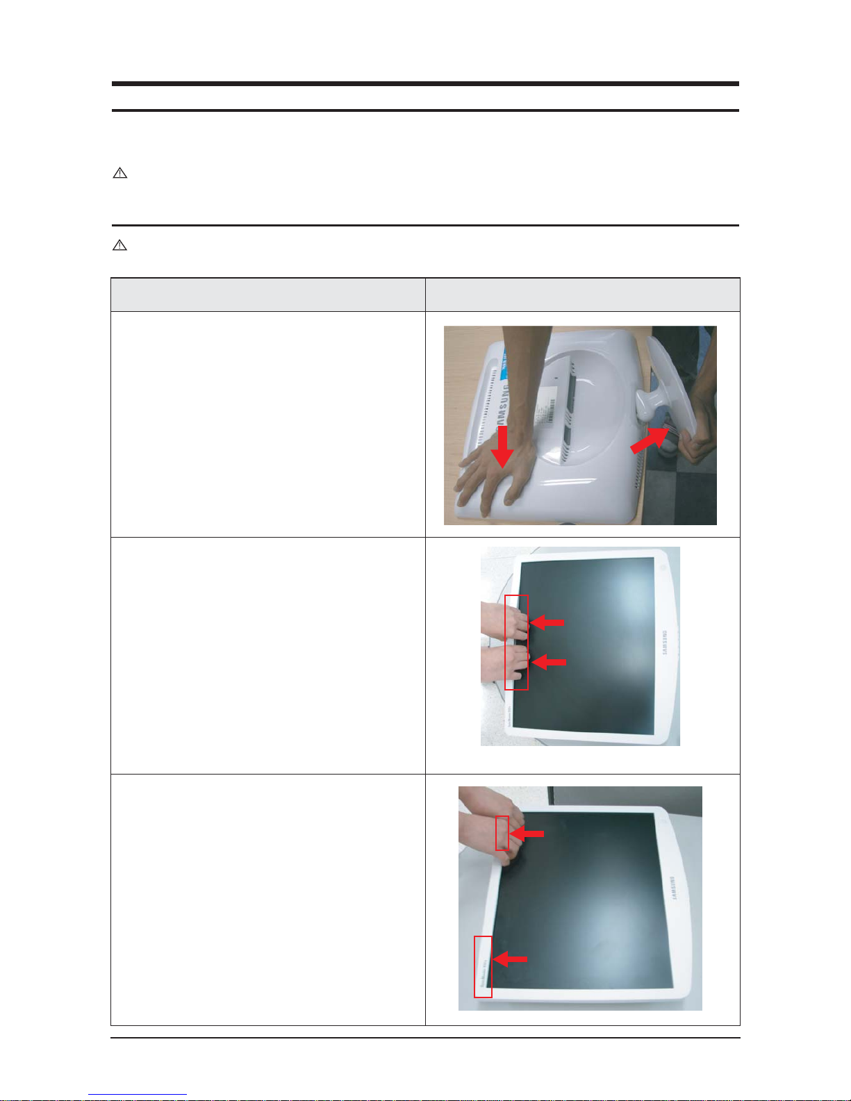
11-1 Disassembly
Cautions: 1. Disassemble stand on a flat desk.
2. Disconnect the monitor from the power source before disassembly.
Description Picture Description
1. Place a soft cloth on the desk and place the
monitor on the cloth upside down. Remove the
stand in the direction of the arrow.
2. Turn the monitor so the front section is facing
upwards. Remove the marked parts from the
front cover, as shown in the figure below.
3. Remove the marked part from the top edge of
the front cover, as shown in the figure below.
11 Disassembly and Reassembly
11-2
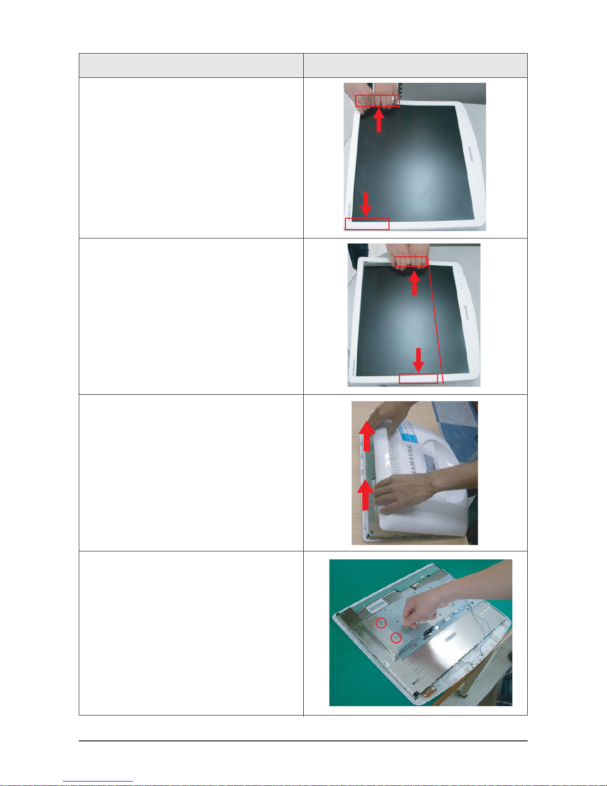
Description Picture Description
4. Remove the marked parts from both sides of
the front cover, as shown in the figure below.
(1)
5. Remove the marked part from the front cover,
as shown in the figure below.
Caution: Do not lift the front cover over position (1),
which may cause damage to it.
6. Turn the monitor so the back of it is facing
upwards. Lift up and remove the back cover.
7. Use the jig to remove the shield lamp.
(Be careful Shield.)
11 Disassembly and Reassembly
11-3
Description Picture Description
LVDS
INVERTER
FUNCTION
LVDS
INVERTER
FUNCTION
19"
17"
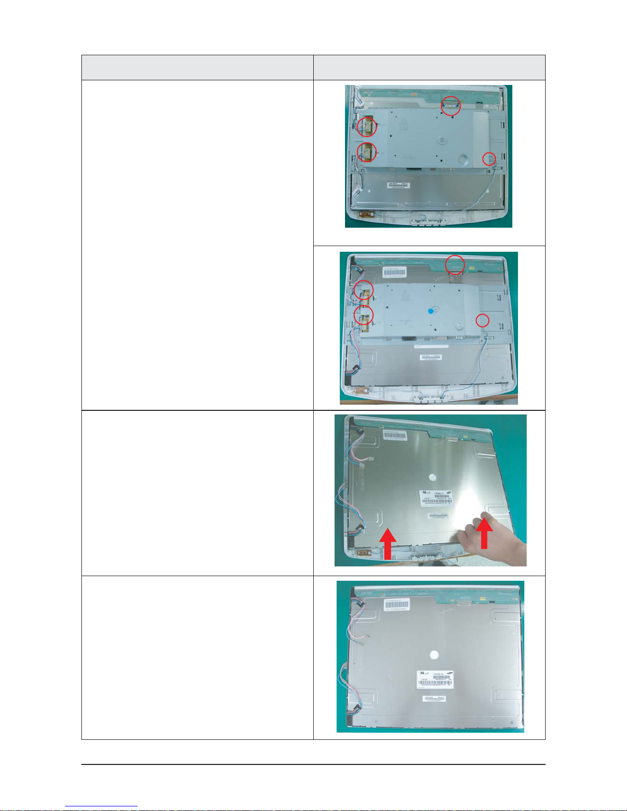
8. Disconnect cables.
(LVDS, INVERTER and FUNCTION cable)
9. Lift up the LCD panel.
10. LCD Panel
11 Disassembly and Reassembly
11-4
설설명 사
사진
설명
11.Remove screws.
(17"=2 screws, 19"=4 screws)
Description Picture Description
19"
17"
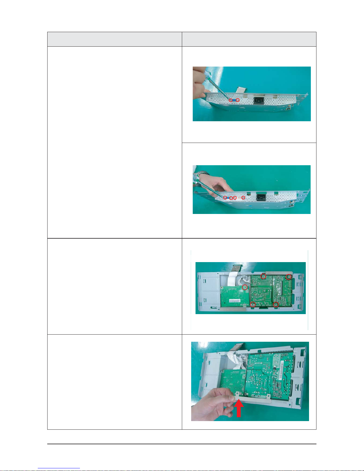
12. Remove 5 screws.
13. Lift up the Bracket Support.
11 Disassembly and Reassembly
11-5
설설명 사
사진
설명
Description Picture Description
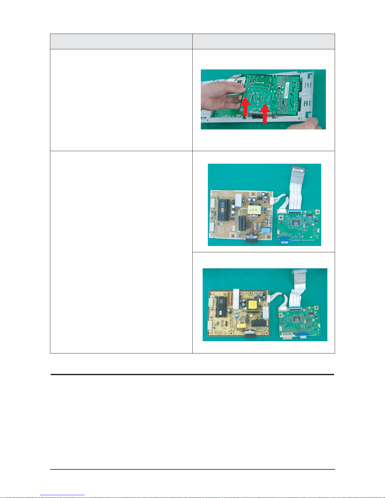
14. Lift up the Main PCB and IB Board.
15. Main PCB and IB Board
19"
17"
11-2 Reassembly
Reassembly procedures are in the reverse order of disassembly procedures.
11 Disassembly and Reassembly
11-6
11-3 Stand
11-3-1 Installing the Stand
설설 명 사사진 설명
Description Picture Description
A: Monitor
Caution
When lifting up or moving the monitor, do not lift the
monitor upside down while holding only the stand, as
this may cause the monitor to fall, leading to damage
or personal injury.
B: Connecting pin
C: Stand
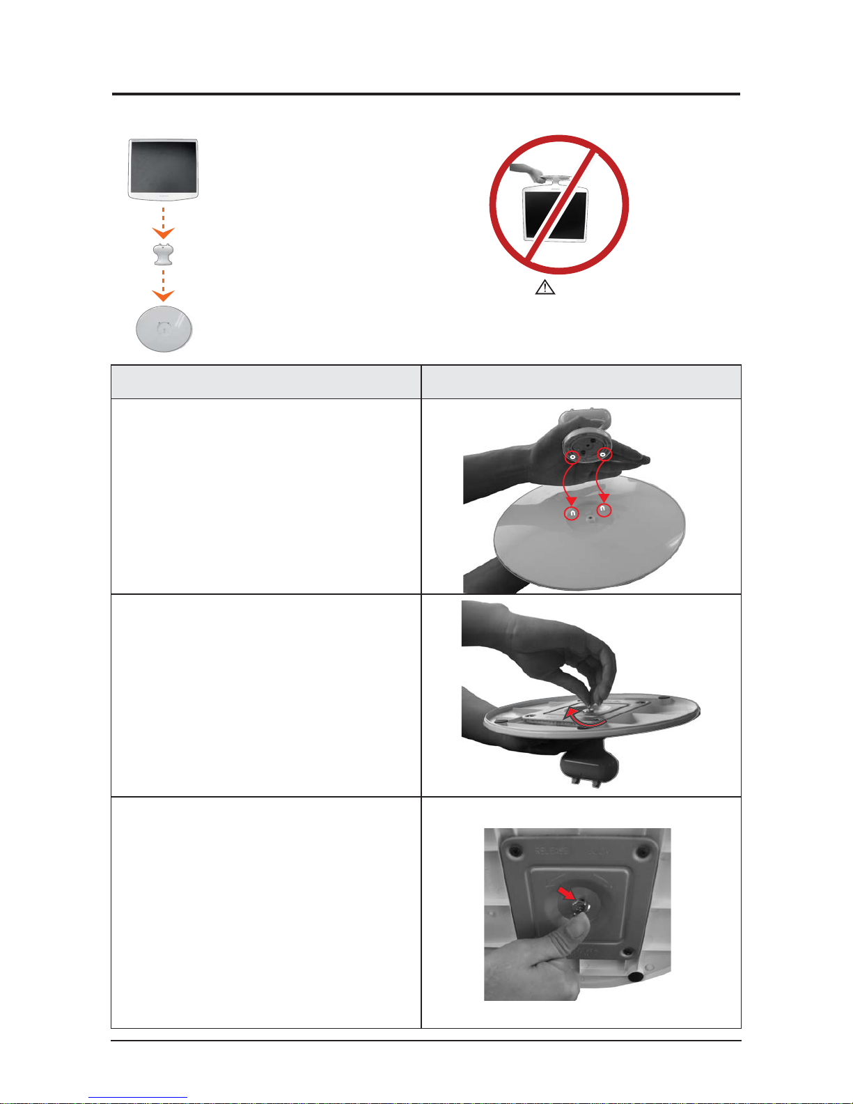
1. Insert the connecting pin into the stand.
2. Stand the screw handles up and tighten the
screws firmly by turning them.
3. Place the screw handles back down.
11 Disassembly and Reassembly
11-7
설설명 사
사진
설명
Description Picture Description
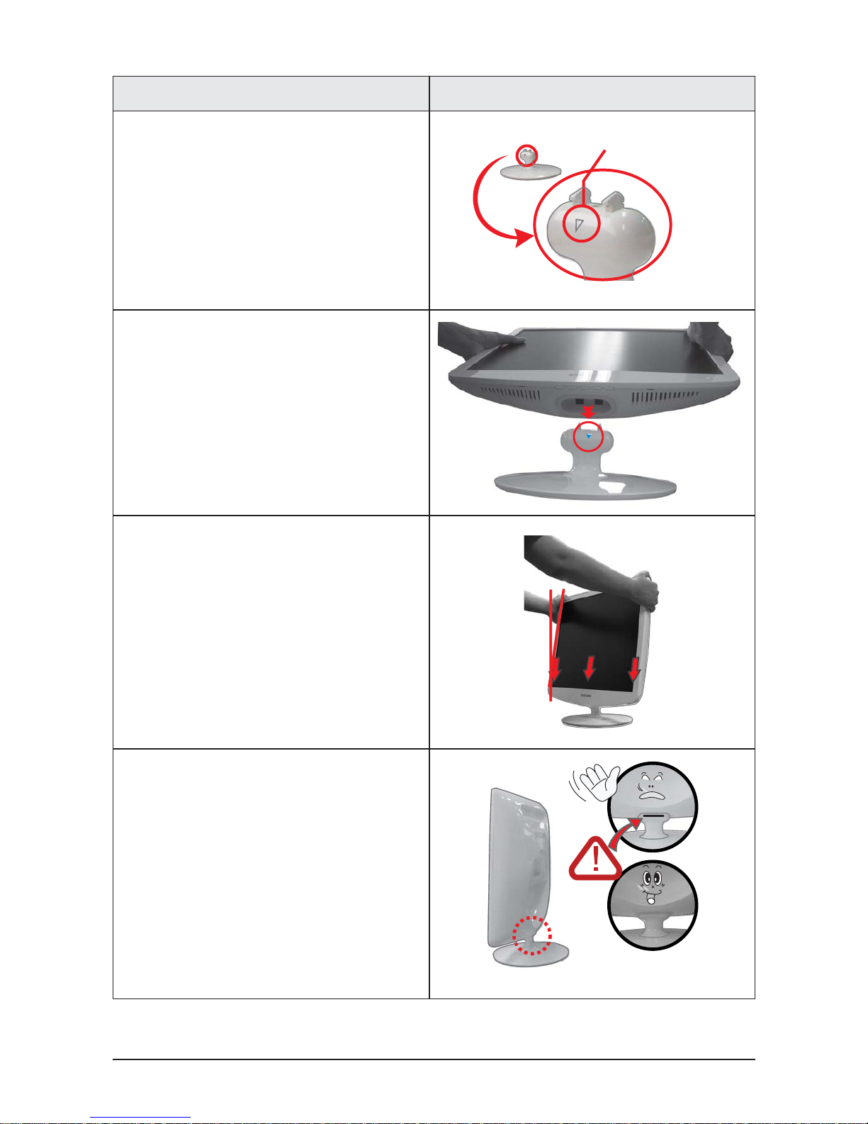
4. Turn the stand so ▽mark on the connecting
pin is facing the front.
4. Check the connecting part between the monitor
and the stand.
4. Tilt the monitor upwards at an angle of 5 ° to
10° so that the base is closer to you than the
top. Then hold the monitor on the stand by its
top parts and push them downwards.
(You can assemble it more easily by pushing it
down while wriggling it a little to the left and right.)
5. When the monitor is assembled correctly, the
straight groove line at the back of the
connecting pin will not be visible when the
monitor is erected at 90° .
Push
11 Disassembly and Reassembly
11-8
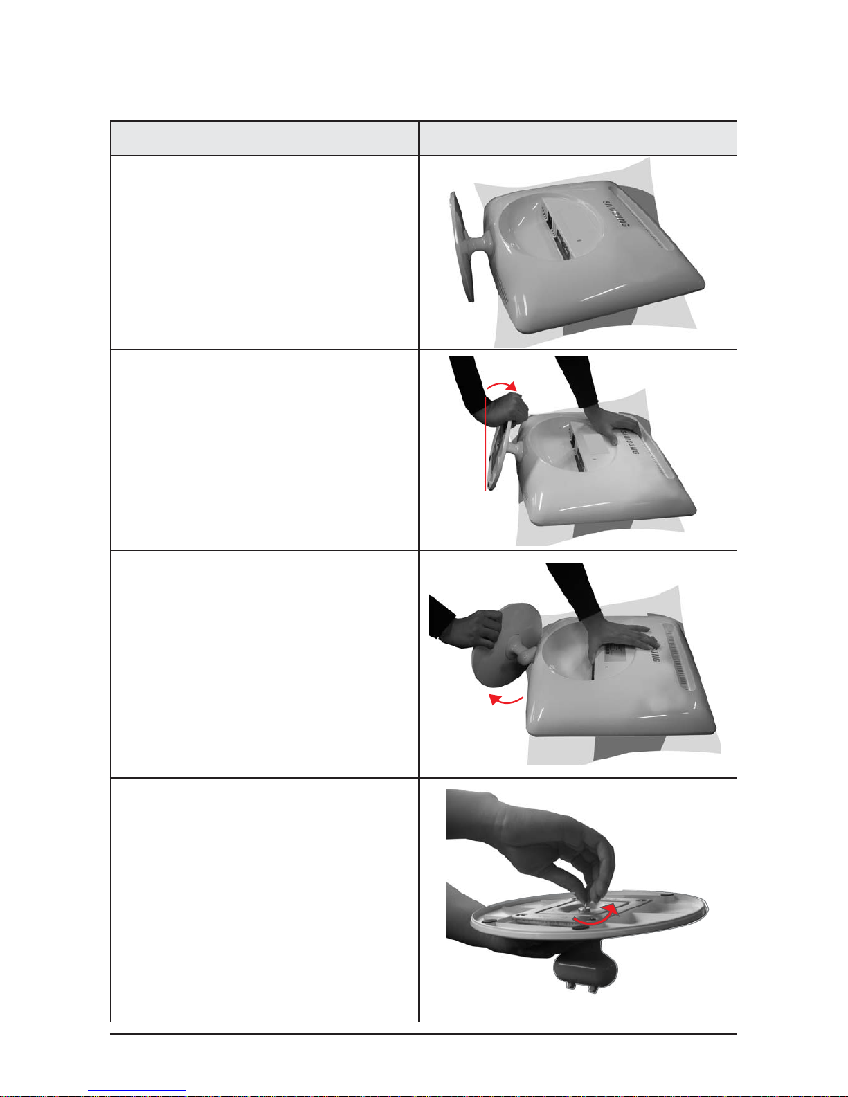
11-3-2 Removing the Stand
설설 명 사사진 설명
Description Picture Description
1. Place a soft cloth or cushion on the table
and place the monitor with the front facing
downwards.
2. Hold the monitor and lean the stand upwards.
3. Hold the monitor, and then twist the stand
strongly to the left and pull it out.
4. Stand the screw handles up and unfasten the
screws by turning them.
11 Disassembly and Reassembly
11-9
설설명 사
사진
설명
Description Picture Description
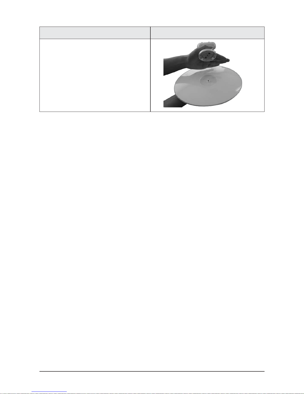
5. Remove the connecting pin from the stand.

11 Disassembly and Reassembly
11-10
Memo
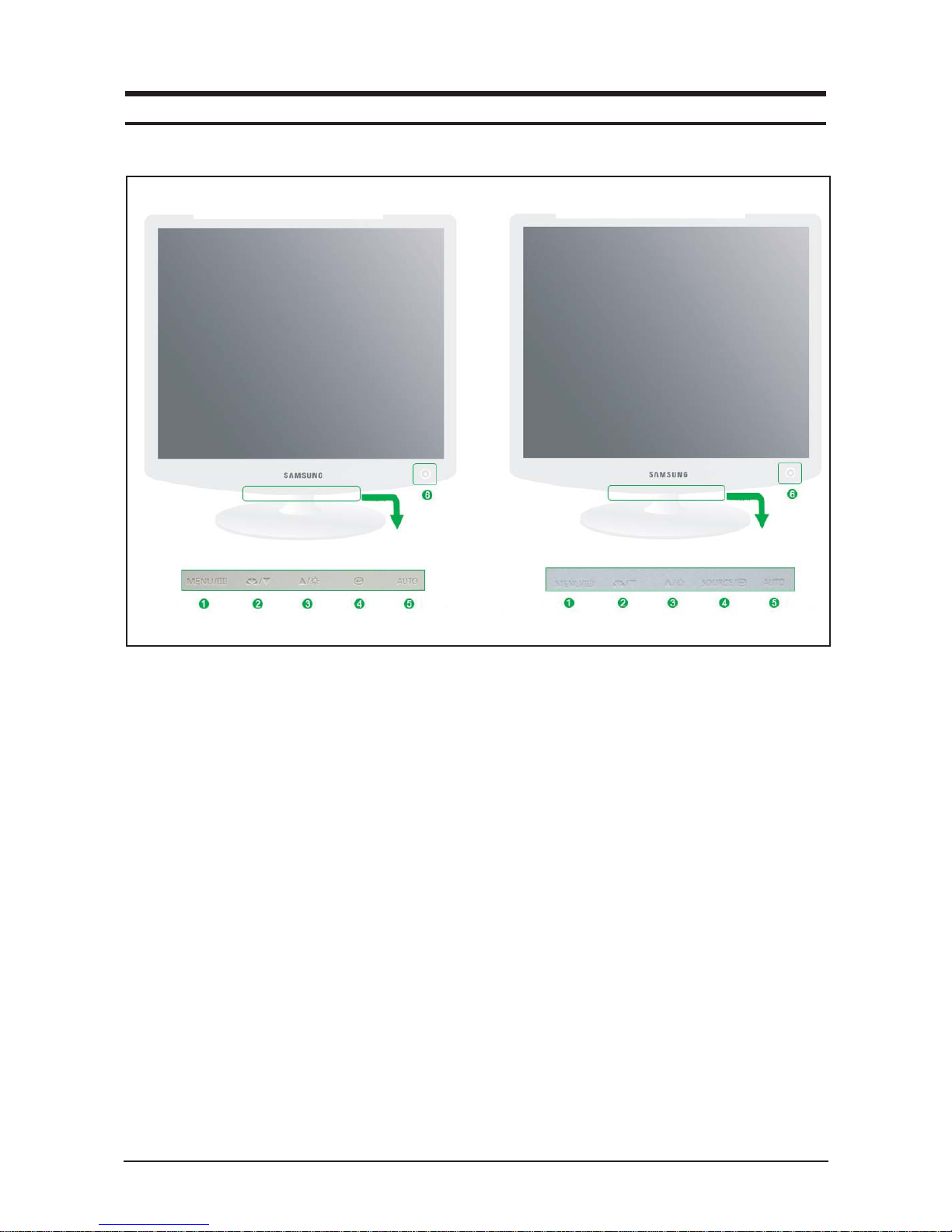
1. Menu button
Opens the OSD menu. Also use to exit the OSD
menu or return to the previous menu.
2. MagicBright button
MagicBright is a new feature providing optimum
viewing environment depending on the contents of
the image you are watching. Currently six different
modes are available: Custom, Text, Internet,
Game, Sport and Movie. Each mode has its own
pre-configured brightness value. You can easily
select one of six settings by simply pressing
MagicBright control buttons.
1) Custom
Although the values are carefully chosen by our
engineers, the pre-configured values may not be
comfortable to your eyes depending on your taste.
If this is the case, adjust the brightness and contrast by using the OSD menu.
2) Text
For documentations or works involving heavy text.
3) Internet
For working with a mixture of images such as text
and graphics.
4) Game
For watching motion pictures such as a game.
5) Sport
For watching motion pictures such as a sport.
6) Movie
For watching motion pictures such as a DVD or
Video CD.
7) Dynamic Contrast
Dynamic Contrast is to automatically detect
distribution of inputted visual signal and adjust to
create optimum contrast.
3. Brightness button
When OSD is not on the screen, push the button
to adjust brightness.
2,3. Adjust buttons
Adjust items in the menu.
4. Enter button (LS17PEA, LS19PEA)
Activates a highlighted menu item.
10 Operating Instructions and Installation
10-1
10 Operating Instructions and Installation
10-1 Front
LS17PEA, LS19PEA
L
LS19PEB
LS17PEA, LS19PEA
LLS19PEB
10 Operating Instructions and Installation
10-2
4. Enter button / SOURCE button (LS19PEB)
Activates a highlighted menu item. /
Push the 'SOURCE', then selects the video signal
while the OSD is off. (When the source button is
pressed to change the input mode, a message
appears in the upper left of the screen displaying
the current mode -- analog or digital input signal.)
5. AUTO button
Use this button for auto adjustment.
6. Power button
Use this button for turn the monitor on and off.
Power indicator
This light glows green during normal operation,
and blinks green once as the monitor saves your
adjustments.
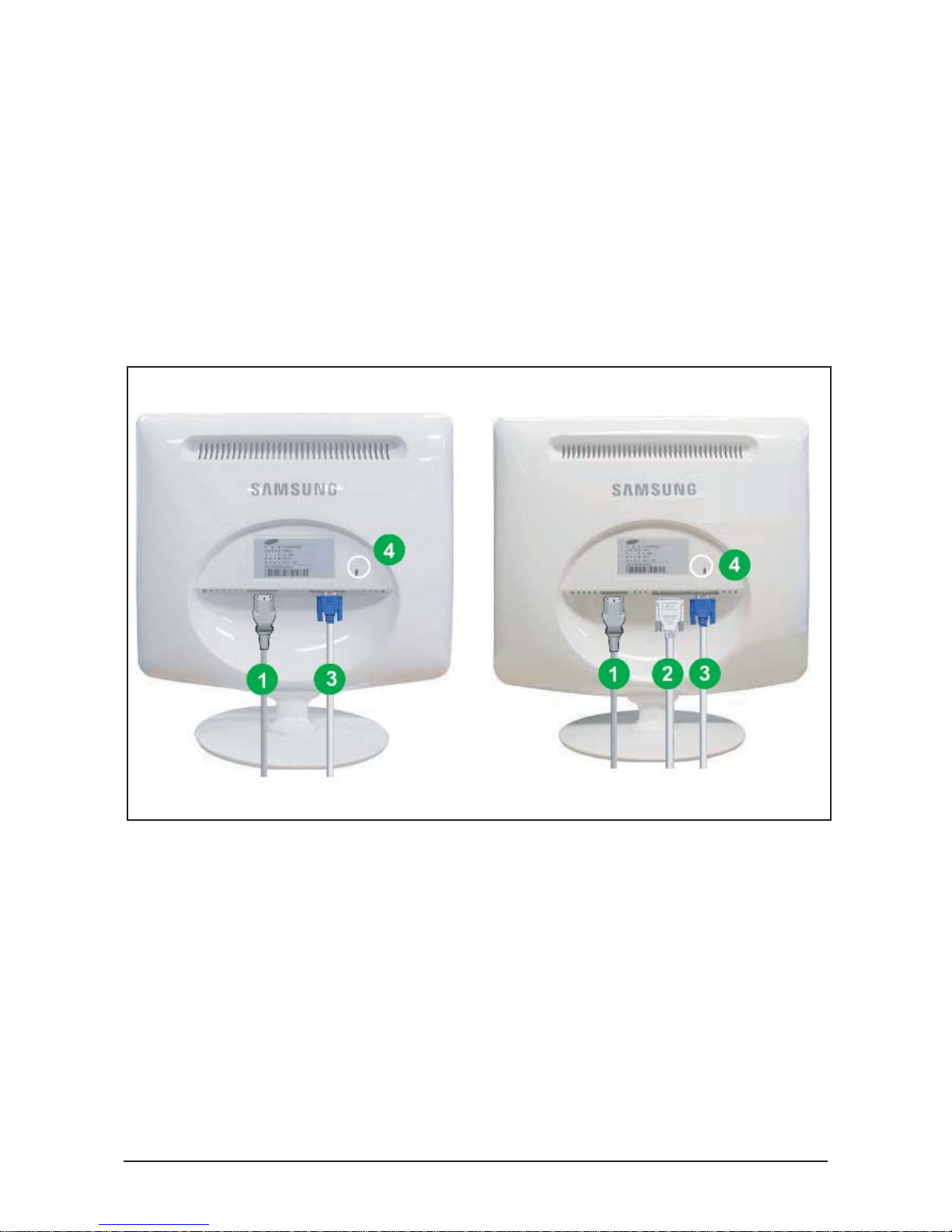
10-2 Rear
(The configuration at the back of the monitor may vary from product to product.)
1. Power port
Connect the power cord for your monitor to the power port on the back of the monitor.
2. DVI IN port
Connect the DVI cable to the DVI port on the back of your monitor.
3. RGB IN port
Connect the signal cable to the 15-pin, D-sub port on the back of your monitor.
4. Kensington Lock
The Kensington lock is a device used to physically fix the system when using it in a public place.
1. Connect the power cord for your monitor to the power port on the back of the monitor.
Plug the power cord for the monitor into a nearby outlet.
2-1. Using the D-sub (Analog) connector on the video card.
Connect the signal cable to the 15-pin, D-sub connector on the back of your monitor.
2-2. Connected to a Macintosh.
Connect the monitor to the Macintosh computer using the D-SUB connection cable.
2-3. In the case of an old model Macintosh, you need to connect the monitor using a special Mac
adapter.
3. Turn on your computer and monitor. If your monitor displays an image, installation is complete.
10 Operating Instructions and Installation
10-3
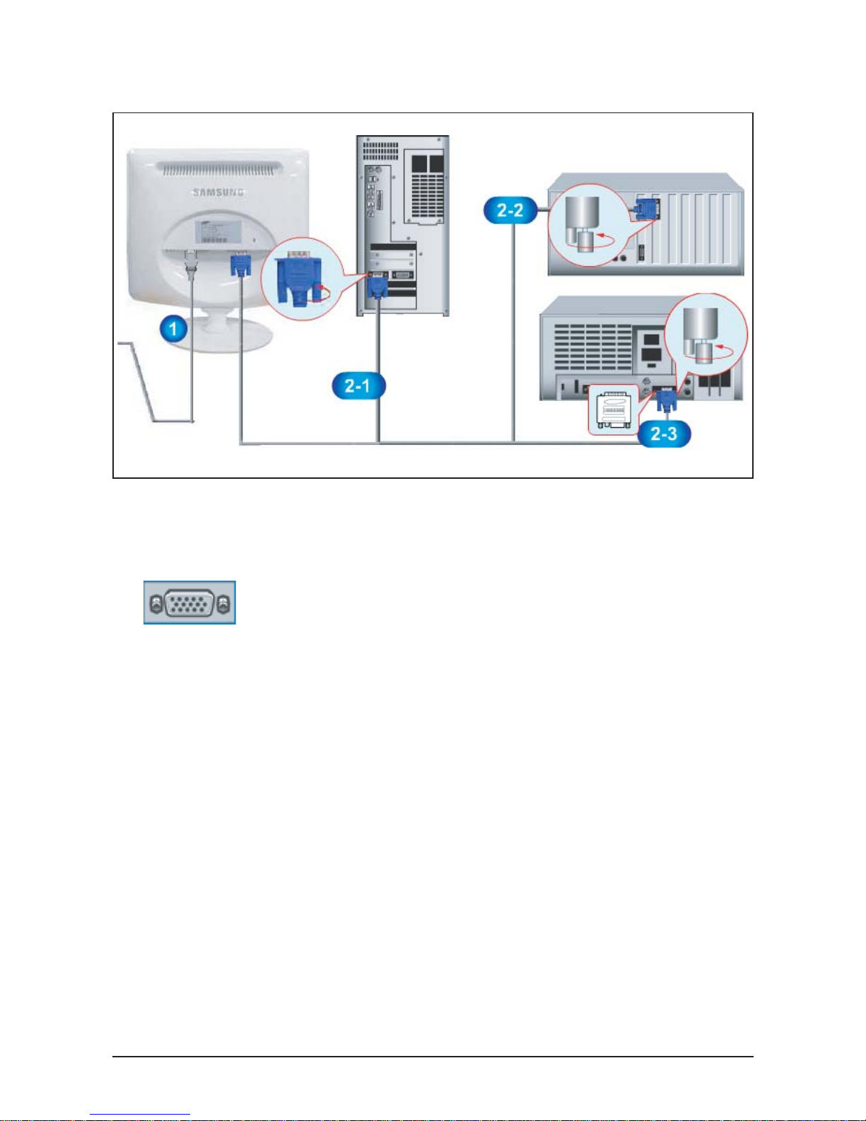
10-3 Connecting the monitor (LS17PEA, LS19PEA)
● Rear of Monitor
● Rear of Computer
● Old Model Macintosh
● New Model Macintosh

10 Operating Instructions and Installation
10-4
1. Connect the power cord for your monitor to the power port on the back of the monitor.
Plug the power cord for the monitor into a nearby outlet.
2-1. Using the D-sub (Analog) connector on the video card.
Connect the signal cable to the 15-pin, D-sub connector on the back of your monitor.
2-2. Using the DVI (Digital) connector on the video card.
Connect the DVI cable to the DVI port on the back of your monitor.
2-3. Connected to a Macintosh.
Connect the monitor to the Macintosh computer using the D-SUB connection cable.
2-4. In the case of an old model Macintosh, you need to connect the monitor using a special Mac
adapter.
3. Turn on your computer and monitor. If your monitor displays an image, installation is complete.
10-3-1 Connecting the monitor (LS19PEB)
● Rear of Monitor
● Rear of Computer
● Old Model Macintosh
● New Model Macintosh
12 PCB Layout
12-1
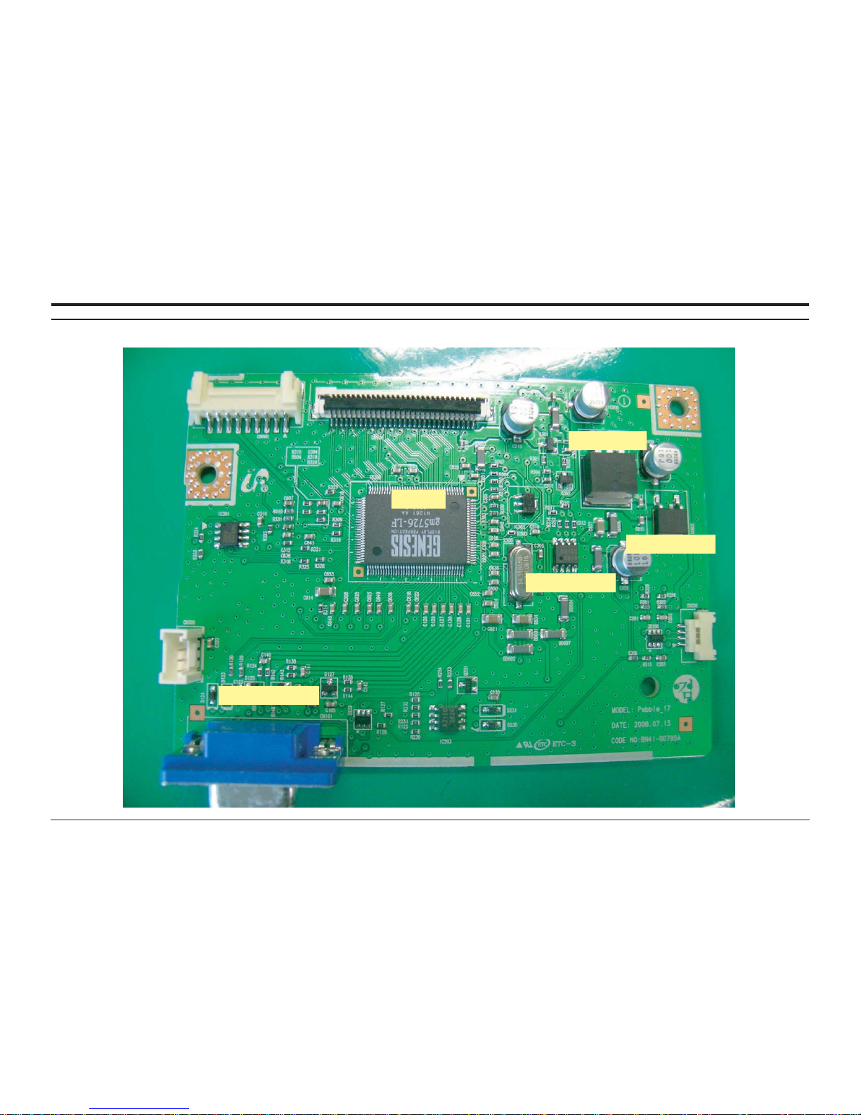
12 PCB Diagram
12-1 Main PCB (LS17PEA, LS19PEA)
Scaler
Flash Memory
Regulator 1.8
EEPROM - Analog
Regulator 3.3
12 PCB Layout
12-2
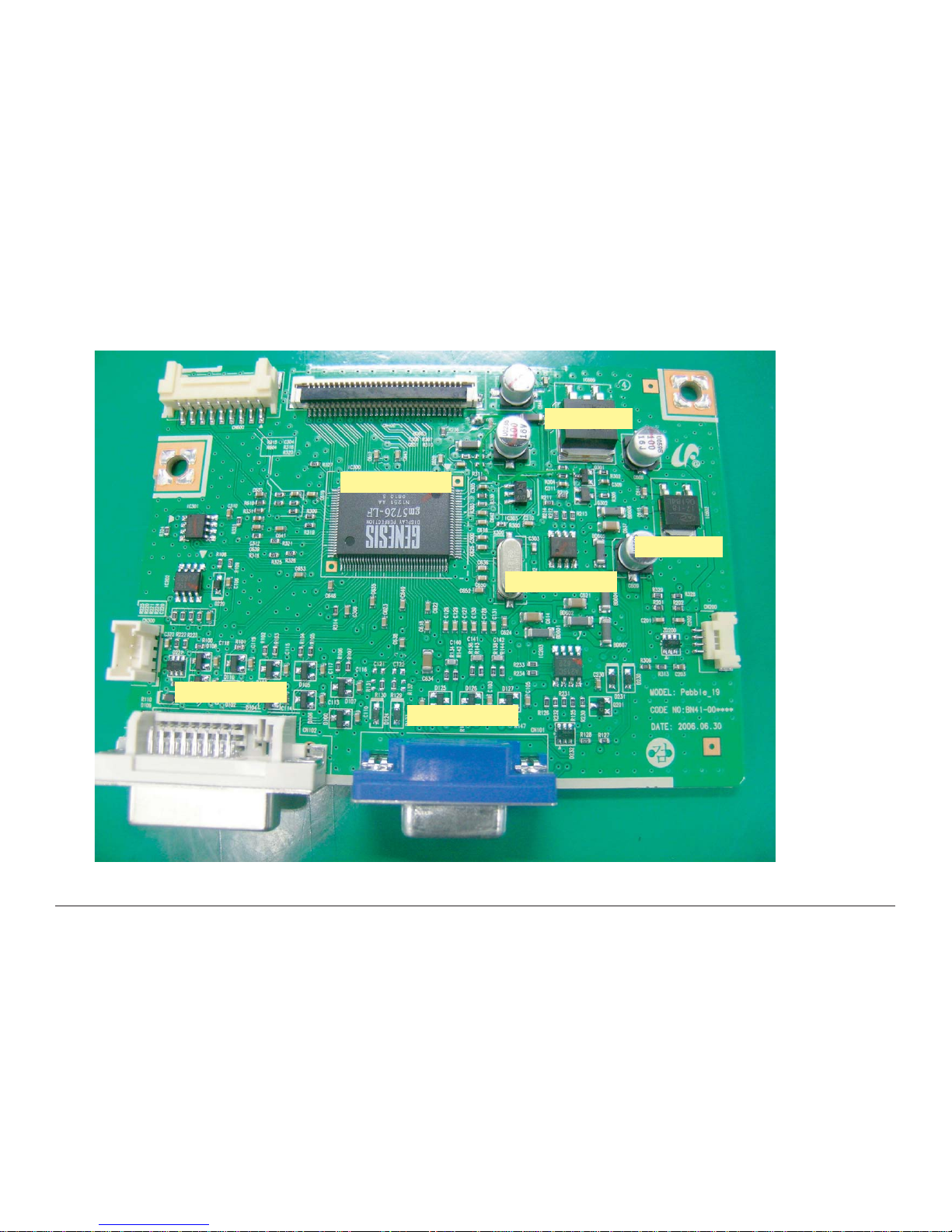
12-2 Main PCB (LS19PEB)
Scaler
EEPROM - Digital
EEPROM - Analog
Flash Memory
Regulator 1.8
Regulator 3.3

14 Reference Infomation
14-1
14 Reference Infomation
14-1 Technical Terms
-TFT-LCD
(Thin film Transistor Liquid Crystal Display)
ADC(Analog to Digital Converter)
This is a circuit that converts from analog signal to
digital signals.
-PLL(Phase Locked Loop)
During progressing ADC, Device makes clock syn-
chronizing HSYNC with Video clock
-Inverter
Device that supplies Power to LCD panel lamp. This
device generates about 1,500~2,000V.
AC Adapter
Device that converts AC(90V~240V) to DC(+12V or
14V)
SMPS(Switching Mode Power Supply)
Switching Mode Power supply. This design technol-
ogy is used to step up/down the input power by
switching on/off
-FRC(Frame Rate Controller)
Technology that changes the number of frames dis-
played on screen per second.
TFT-LCD panel requires 60 frames per second.
This technology is needed to convert input image to
60 frames per second regardless input frame quan-
tity.
-Image Scaler
Technology that converts an input resolution to
another resolution.(ex. 640* 480 to 1024*768)
-Auto Configuration(Auto adjustment)
This is an algorithm to adjust monitor to optimum
condition by pushing one key.
-OSD(On Screen Display)
Customers can easily control the screen settings
using the OSD.
-FINE
The "Fine" adjustment is used to adjust visibility by
controlling phase difference.
-COARSE
This adjustment adjusts the display by tuning Video
clock and PLL clock.
-DVI (Digital Visual Interface)
This provides a high speed digital connection for
visual data types that is display technology inde-
pendent. This interface is primarily forcused at pro-
viding a connection between a computer and
its display device.
-L.V.D.S.(Low Voltage Differential Signaling)
A kind of transmission method for Digital.It can be
used from Main PBA to Panel.
-T.M.D.S
(Transition minimized Differential Signaling)
a kind of transmission method for Digital.
It can be used from Video card to Main PBA.
-DDC(Display data channel)
It is a communication method between Host
Computer and related equipment.
It enables Plug and Play between PC and Monitor.
-EDID
Extended Display Identification Data PC can recog-
nize monitor information such as Product data,
Product name,Display mode,Serial number and
Signal source, etc Data is recognised via DDC Line
linking PC and Monitor.
-Dot Pitch
The image on a monitor is composed of red, green
and blue dots. The closer the dots, the higher the
resolution. The distance between two dots of the
same color is called the 'Dot Pitch'. Unit: mm
-Vertical Frequency
The screen must be redrawn several times per second in order to create and display an image for the

14 Reference Infomation
14-2
user. The frequency of this repetition per second is
called Vertical Frequency or Refresh Rate. Unit: Hz
Example: If the same light repeats itself 60 times
per second, this is regarded as 60 Hz.
-Horizontal Frequency
The time to scan one line connecting the right edge
to the left edge of the screen horizontally is called
Horizontal Cycle. The inverse number of the
Horizontal Cycle is called Horizontal Frequency.
Unit: kHz
-Interlace and Non-Interlace Methods
Showing the horizontal lines of the screen from the
top to the bottom in order is called the Non-Interlace
method while showing odd lines and then even lines
in turn is called the Interlace method. The NonInterlace method is used for the majority of monitors
to ensure a clear image. The Interlace method is the
same as that used in TVs.
-Plug & Play
This is a function that provides the best quality
screen for the user by allowing the computer and
the monitor to exchange information automatically.
This monitor follows the international standard
VESA DDC for the Plug & Play function.
-Resolution
The number of horizontal and vertical dots used to
compose the screen image is called 'resolution'.
This number shows the accuracy of the display.
High resolution is good for performing multiple tasks
as more image information can be shown on the
screen.
Example: If the resolution is 1280 x 1024 , this
means the screen is composed of 1280 horizontal
dots (horizontal resolution) and 1024 vertical lines
(vertical resolution).
14 Reference Infomation
14-3
Sync
Type
Pin No.
15-Pin D-Sub Signal Cable Connector
Separate Composite
1
2
3
4
5
6
7
8
9
10
11
12
13
14
15
Red
Green
Blue
GND
DDC Return (GND)
GND-R
GND-G
GND-B
DDC Power Input (+5V)
Self Raster
GND
Bi-Dr Data (SDA)
H-Sync.
V-Sync.
DDC Clock (SCL)
Red
Green
Blue
GND
DDC Return (GND)
GND-R
GND-G
GND-B
DDC Power Input (+5V)
Self Raster
GND
Bi-Dr Data (SDA)
H/V-Sync.
Not Used
DDC Clock (SCL)
Red
Green + H/V Sync.
Blue
GND
DDC Return (GND)
GND-R
GND-G
GND-B
DDC Power Input (+5V)
Self Raster
GND
Bi-Dr Data (SDA)
Not Used
Not Used
DDC Clock (SCL)
Sync-on-green
No Connection
+5V_M
Self Raster
+5V_M
Rx0-
Rx0+
NC
No Connection
No Connection
NC
RxC+
RxC-
13
14
15
16
17
18
19
20
21
22
23
24
1
2
3
4
5
6
7
8
9
10
11
12
Rx2-
Rx2+
GND
No Connection
No Connection
DDC Clock (SCL)
DDC Data (SDA)
NC
Rx1-
Rx1+
NC
No Connection
Sync
Type
Pin No.
24P DVI-D
14-2 Pin Assignments
14 Reference Infomation
14-4
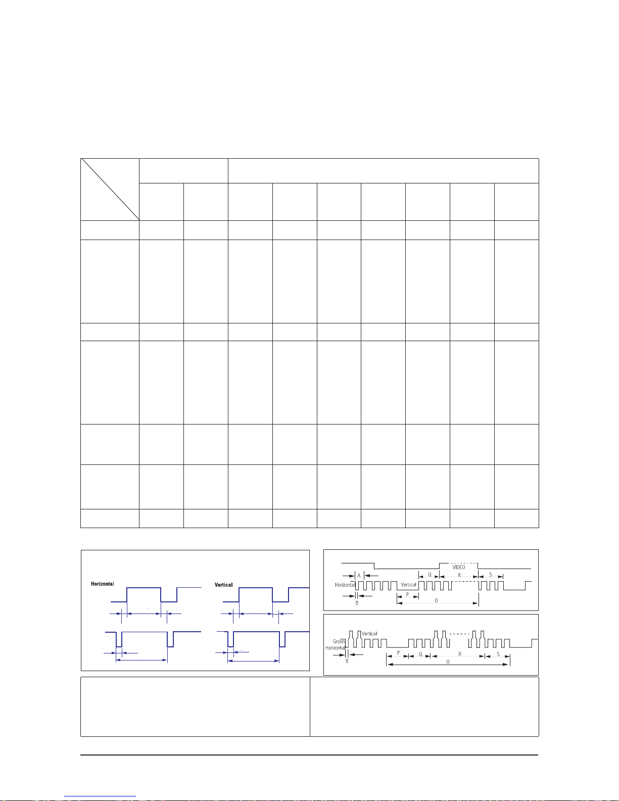
Separate Sync
14-3 Timing Chart
C D
A
O
E
B
P
Video
Sync
Sync
Video
Q R S
A : Line time total B : Horizontal sync width O : Frame time total
P : Vertical sync width
C : Back porch D : Active time Q : Back porch
R : Active time
H/V Composite Sync
Sync-on-Green
79.975
12.504
1.067
1.837
9.481
0.119
75.025
13.329
0.038
0.475
12.804
0.013
135.000
Positive
Positive
Separate
1280/75 Hz
1280x1024
1280/60 Hz
1280x1024
63.981
11.852
1.037
2.296
9.259
0.000
60.020
16.005
0.047
0.594
15.630
0.016
108.000
Positive
Positive
Separate
31.469
31.777
3.813
1.589
26.058
0.318
70.087
14.268
0.064
0.858
13.155
0.191
28.322
Negative
Positive
Separate
fH (kHz)
A μsec
B μsec
C μsec
D μsec
E μsec
fV (Hz)
O msec
P msec
Q msec
R msec
S msec
Clock
Freq.
(MHz)
Polarity
H.Sync
V.Sync
Remark
IBM
640/75 Hz
640x480
800/60 Hz
800x600
800/75 Hz
800x600
1024/60 Hz
1024x768
1024/75 Hz
1024x768
VGA2/
70 Hz
720 x 400
VGA3/
60 Hz
640 x 480
Table 14-1 Timing Chart
31.469
31.778
3.813
1.589
26.058
0.318
59.940
16.683
0.064
0.794
15.761
0.064
26.175
Negative
Negative
Separate
37.500
26.667
2.032
3.810
20.317
0.508
75.000
13.333
0.080
0.427
12.800
0.027
31.500
Negative
Negative
Separate
37.879
26.400
3.200
2.200
20.000
0.000
60.317
16.579
0.106
0.607
15.840
0.0261
40.000
Positive
Positive
Separate
46.875
21.333
1.616
3.232
16.162
0.323
75.000
13.333
0.064
0.448
12.800
0.021
49.500
Positive
Positive
Separate
48.363
20.677
2.092
2.462
15.754
0.369
60.004
16.666
0.124
0.600
15.880
0.062
75.000
Negative
Negative
Separate
60.023
16.660
1.219
2.235
13.003
0.203
75.029
13.328
0.050
0.466
12.795
0.017
78.750
Positive
Positive
Separate
Mode
VESA
Timing
This section of the service manual describes the timing that the computer industry recognizes as standard for computergenerated video signals.
 Loading...