

Samsung 510N, 911N, 920N, 510T, 710N Service Manual
...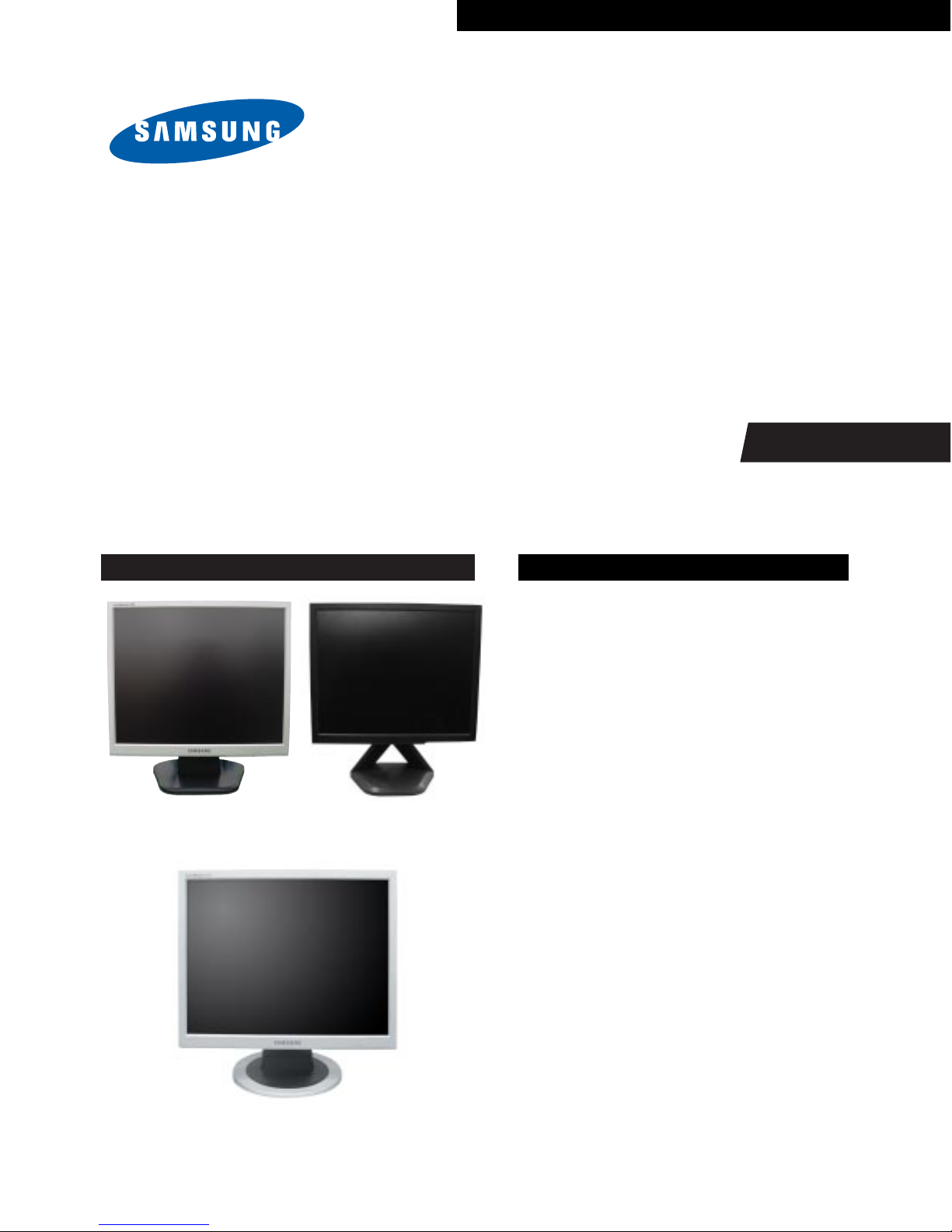
TFT-LCD MONITOR
Chassis Model
MJ15AS* 510N
MJ15BS* 510T
MJ17AS* 710N
MJ17BS* 710T
MJ19AS* 910N, 911N, 920N
MJ19BS* 910T
MJ19ES* 913N
MJ19US* 915N
MJ19QS* 913T, 910B
MJ19DS* 912T
Manual
SERVICE
TFT-LCD MONITOR CONTENTS
1. Precautions
2. Product Specifications
3. Disassembly & Reassembly
4. Alignments & Adjustments
5. Troubleshooting
6. Exploded View & Parts List
7. Electrical Parts List
8. Block Diagram
9. Wiring Diagram
10. PCB Layout
11. Schematic Diagrams
12. Panel Description
Simple Stand Pivot Stand
Simple Stand
1 Precautions
1-1
1-1-1 Warnings
1. For continued safety, do not attempt to modify the circuit
board.
2. Disconnect the AC power and DC power jack before
servicing.
1-1-2
Servicing the LCD Monitor
1. When servicing the LCD Monitor, Disconnect the AC
line cord from the AC outlet.
2. It is essential that service technicians have an accurate
voltage meter available at all times. Check the
calibration of this meter periodically.
1-1-3 Fire and Shock Hazard
Before returning the monitor to the user, perform the
following safety checks:
1. Inspect each lead dress to make certain that the leads are
not pinched or that hardware is not lodged between the
chassis and other metal parts in the monitor.
2. Inspect all protective devices such as nonmetallic control
knobs, insulating materials, cabinet backs, adjustment
and compartment covers or shields, isolation resistorcapacitor networks, mechanical insulators, etc.
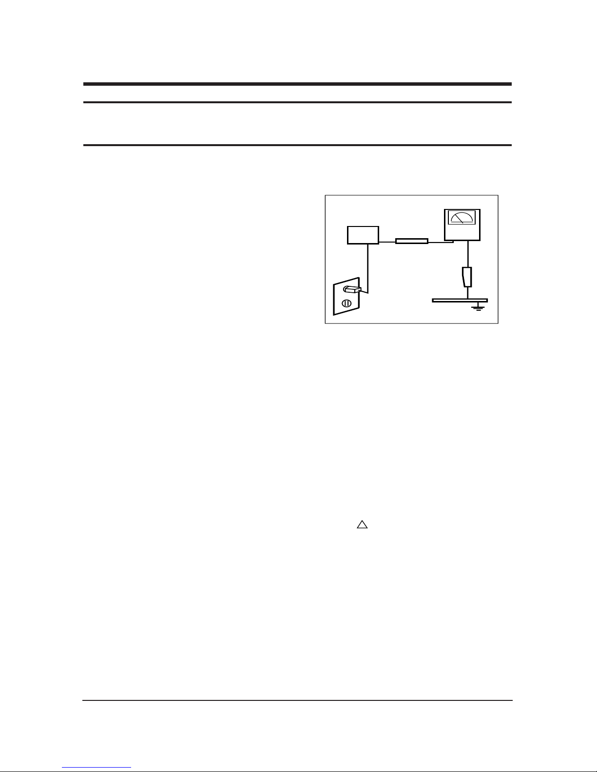
3. Leakage Current Hot Check (Figure 1-1):
WARNING: Do not use an isolation
transformer during this test.
Use a leakage current tester or a metering system that
complies with American National Standards Institute
(ANSI C101.1, Leakage Current for Appliances), and
Underwriters Laboratories (UL Publication UL1410,
59.7).
Figure 1-1. Leakage Current Test Circuit
4. With the unit completely reassembled, plug the AC line
cord directly into a 120V AC outlet. With the unit’s AC
switch first in the ON position and then OFF, measure
the current between a known earth ground (metal water
pipe, conduit, etc.) and all exposed metal parts,
including: metal cabinets, screwheads and control shafts.
The current measured should not exceed 0.5 milliamp.
Reverse the power-plug prongs in the AC outlet and
repeat the test.
1-1-4 Product Safety Notices
Some electrical and mechanical parts have special safetyrelated characteristics which are often not evident from visual
inspection. The protection they give may not be obtained by
replacing them with components rated for higher voltage,
wattage, etc. Parts that have special safety characteristics are
identified by on schematics and parts lists. A substitute
replacement that does not have the same safety characteristics
as the recommended replacement part might create shock, fire
and/or other hazards. Product safety is under review
continuously and new instructions are issued whenever
appropriate.
1 Precautions
Follow these safety, servicing and ESD precautions to prevent damage and to protect against potential hazards such as electrical shock.
1-1 Safety Precautions
DEVICE
UNDER
TEST
TEST ALL
EXPOSED METAL
SURFACES
(READING SHOULD
NOT BE ABOVE 0.5mA)
LEAKAGE
CURRENT
TESTER
2-WIRE CORD
*ALSO TEST WITH
PLUG REVERSED
(USING AC ADAPTER
PLUG AS REQUIRED)
EARTH
GROUND
!

1 Precautions
1-2
1-2-1
General Ser vicing Precautions
1. Always unplug the unit’s AC power cord from the AC
power source and disconnect the DC Power Jack before
attempting to:
(a) remove or reinstall any component or assembly, (b)
disconnect PCB plugs or connectors, (c) connect a test
component in parallel with an electrolytic capacitor.
2. Some components are raised above the printed circuit
board for safety. An insulation tube or tape is sometimes
used. The internal wiring is sometimes clamped to
prevent contact with thermally hot components. Reinstall
all such elements to their original position.
3. After servicing, always check that the screws,
components and wiring have been correctly reinstalled.
Make sure that the area around the serviced part has not
been damaged.
1. Immediately before handling any semiconductor
components or assemblies, drain the electrostatic charge
from your body by touching a known earth ground.
Alternatively, wear a discharging wrist-strap device. To
avoid a shock hazard, be sure to remove the wrist strap
before applying power to the monitor.
2. After removing an ESD-equipped assembly, place it on a
conductive surface such as aluminum foil to prevent
accumulation of an electrostatic charge.
3. Do not use freon-propelled chemicals. These can
generate electrical charges sufficient to damage ESDs.
4. Use only a grounded-tip soldering iron to solder or
desolder ESDs.
5. Use only an anti-static solder removal device. Some
solder removal devices not classified as “anti-static” can
generate electrical charges sufficient to damage ESDs.
4. Check the insulation between the blades of the AC plug
and accessible conductive parts (examples: metal panels,
input terminals and earphone jacks).
5. Insulation Checking Procedure: Disconnect the power
cord from the AC source and turn the power switch ON.
Connect an insulation resistance meter (500 V) to the
blades of the AC plug.
The insulation resistance between each blade of the AC
plug and accessible conductive parts (see above) should
be greater than 1 megohm.
6. Always connect a test instrument’s ground lead to the
instrument chassis ground before connecting the positive
lead; always remove the instrument’s ground lead last.
6. Do not remove a replacement ESD from its protective
package until you are ready to install it. Most
replacement ESDs are packaged with leads that are
electrically shorted together by conductive foam,
aluminum foil or other conductive materials.
7. Immediately before removing the protective material
from the leads of a replacement ESD, touch the
protective material to the chassis or circuit assembly into
which the device will be installed.
Caution:Be sure no power is applied to the
chassis or circuit and observe all
other safety precautions.
8. Minimize body motions when handling unpackaged
replacement ESDs. Motions such as brushing clothes
together, or lifting your foot from a carpeted floor can
generate enough static electricity to damage an ESD.
1-3
Electrostatically Sensitive Devices (ESD) Precautions
Some semiconductor (solid state) devices can be easily damaged by static electricity. Such components are commonly called
Electrostatically Sensitive Devices (ESD). Examples of typical ESD are integrated circuits and some field-effect transistors. The
following techniques will reduce the incidence of component damage caused by static electricity.
1-2 Ser vicing Precautions
WARNING: An electrolytic capacitor installed with the wrong polarity might explode.
Caution: Before servicing units covered by this service manual, read and follow the Safety Precautions
section of this manual.
Note: If unforeseen circumstances create conflict between the following servicing precautions and any of the
safety precautions, always follow the safety precautions.
2 Product Specifications
2-1
2 Product Specifications
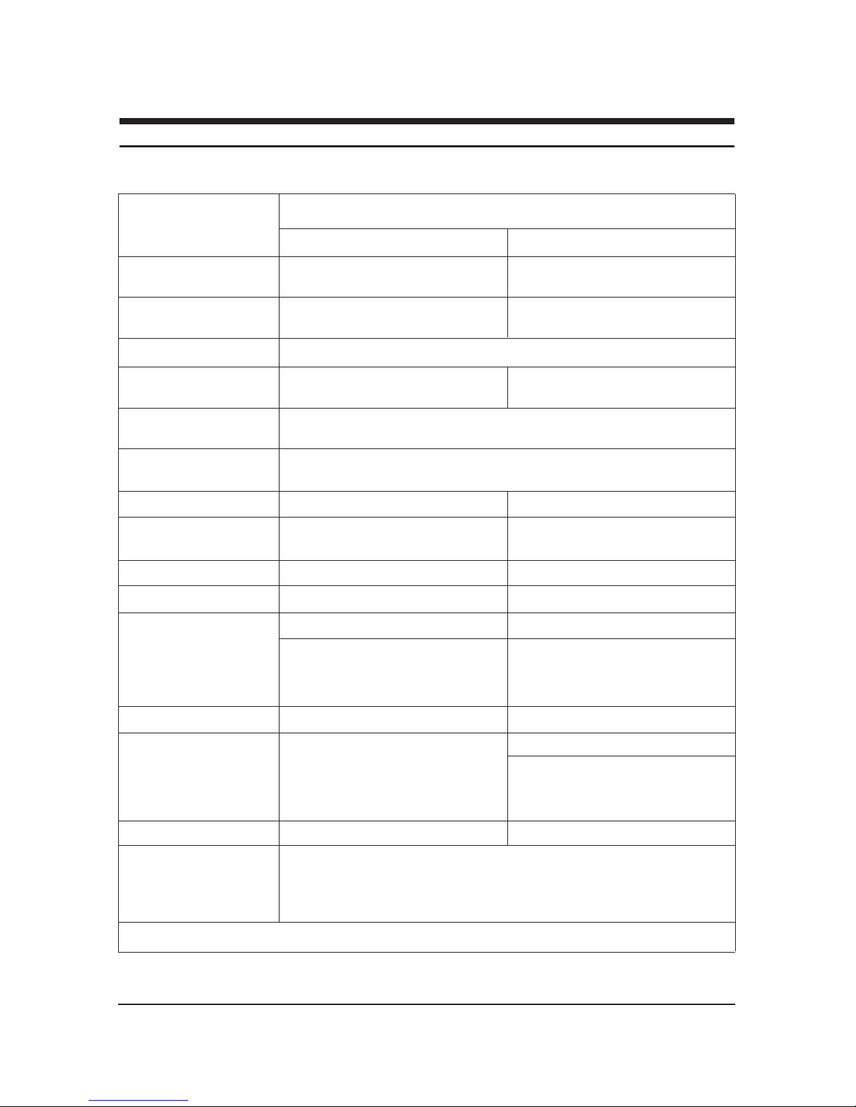
2-1 MJ15AS*/MJ15BS*/MJ17AS*/MJ17BS* Specifications
LCD Panel
TFT-LCD panel, RGB vertical stripe, normally black transmissive, TFT-LCD panel, RGB vertical stripe, normally black transmissive,
15-Inch viewable, 0.297 (H) x 0.297 (V) mm pixel pitch
17-Inch viewable, 0.264 (H) x 0.264 (V) mm pixel pitch
Scanning Frequency
Horizontal : 31 kHz ~ 61 kHz (Automatic) Horizontal : 30 kHz ~ 81 kHz (Automatic)
Vertical : 50 Hz ~ 75 Hz Vertical : 56 Hz ~ 75 Hz
Display Colors 16.2 Million colors
Maximum Resolution Horizontal : 1024 Pixels Horizontal : 1280 Pixels
Vertical : 768 Pixels Vertical : 1024 Pixels
Input Video Signal
Analog, 0.714 Vp-p ± 5% positive at 75 Ω, [Digital(TMDS): MJ15BS*, MJ17BS*]
internally terminated
Input Sync Signal Type : Separate H/V sync, Composite H/V
Level : TTL level (V high ≥ 2.0 V, V low ≤ 0.8 V), Sync-on-Green (≤ –0.25 V)
Maximum Pixel Clock rate 80 MHz 135 MHz
Active Display
Horizontal/Vertical 304.1 mm / 228.1 mm 338 ± 3 mm / 270 ± 3 mm
AC power voltage & Frequency AC 90 ~ 264 Volts, 60/50 Hz ± 12V / 3A
AC 90 ~ 264 Volts, 60/50 Hz ± 3 Hz
Power Consumption 25W (normal) 34W (normal)
Dimensions
Set (W x D x H)
13.3 x 2.2 x 10.7 Inches (338.0 x 56.3 x 272.0 mm) State of stand disassembled 14.6 x 2.4 x 12.4 Inches (370.0 x 60.3 x 316.0 mm) State of stand disassembled
13.3 x 6.9 x 13.3 Inches (338.0 x 175.0 x 337.0 mm) State of stand installed 14.6 x 6.9 x 15 Inches (370.0 x 175.0 x 381.0 mm) State of stand installed
Package
15.3 x 4.9 x 15.1 Inches (388 x 125 x 383 mm) 17.9 x 5.6 x 17.2 Inches (455 x 141 x 437 mm)
Weight (Set/Package)
Dimensions
Set (W x D x H)
14.6 x 2.4 x 12.4 Inches (370.0 x 60.3 x 316.0 mm) State of stand disassembled
14.6 x 7.5 x 16.0 Inches (370.0 x 190.9 x 406.8 mm) State of stand installed
Package
20.0 x 10.1 x 16.0 Inches (508 x 256 x 407 mm)
Weight (Set/Package)
Environmental Considerations
Operating Temperature : 50°F ~ 104°F (10°C ~ 40°C)
Operating Humidity : 10 % ~ 80 %
Storage Temperature : -13°F ~ 113°F (-25°C ~ 45°C)
Storage Humidity : 5 % ~ 95 %
• Designs and specifications are subject to change without prior notice.
Description
MJ15AS*/MJ15BS* MJ17AS*/MJ17BS*
3.1 kg (6.8 lbs) / 4.25 kg (9.4 lbs)
Simple StandSimple Stand / Pivot Stand
Pivot Stand
4.5 kg (9.9 lbs) / 6.15 kg (13.6 lbs)
-
-
6.25 kg (13.8 lbs) / 7.95 kg (17.5 lbs)
Item
2 Product Specifications
2-3
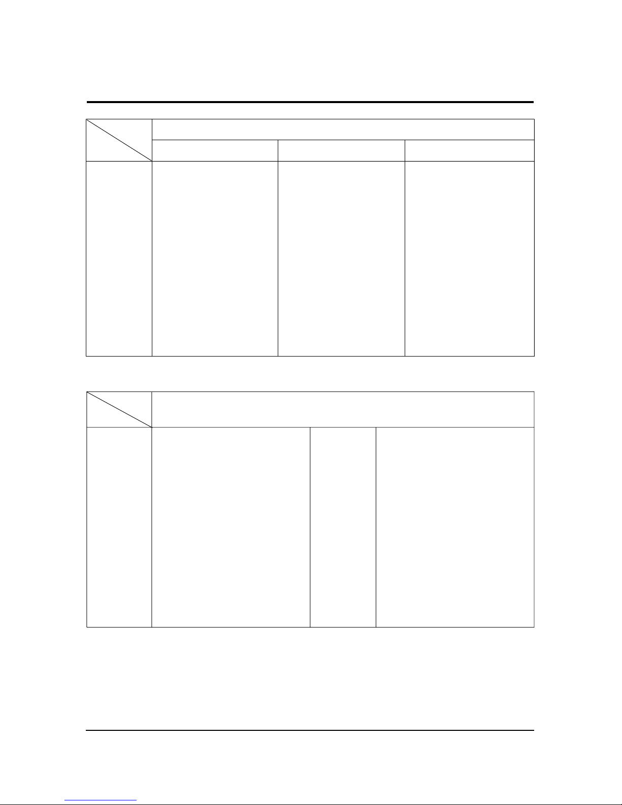
2-3 Pin Assignments
Sync
Type
Pin No.
15-Pin D-Sub Signal Cable Connector
Separate Composite
1
2
3
4
5
6
7
8
9
10
11
12
13
14
15
Red
Green
Blue
GND
DDC Return (GND)
GND-R
GND-G
GND-B
DDC Power Input (+5V)
Self Raster
GND
Bi-Dr Data (SDA)
H-Sync.
V-Sync.
DDC Clock (SCL)
Red
Green
Blue
GND
DDC Return (GND)
GND-R
GND-G
GND-B
DDC Power Input (+5V)
Self Raster
GND
Bi-Dr Data (SDA)
H/V-Sync.
Not Used
DDC Clock (SCL)
Red
Green + H/V Sync.
Blue
GND
DDC Return (GND)
GND-R
GND-G
GND-B
DDC Power Input (+5V)
Self Raster
GND
Bi-Dr Data (SDA)
Not Used
Not Used
DDC Clock (SCL)
Sync-on-green
No Connection
+5V_M
Self Raster
+5V_M
Rx0-
Rx0+
NC
No Connection
No Connection
NC
RxC+
RxC-
13
14
15
16
17
18
19
20
21
22
23
24
1
2
3
4
5
6
7
8
9
10
11
12
Rx2-
Rx2+
GND
No Connection
No Connection
DDC Clock (SCL)
DDC Data (SDA)
NC
Rx1-
Rx1+
NC
No Connection
Sync
Type
Pin No.
24P DVI-D
2 Product Specifications
2-4
Separate Sync
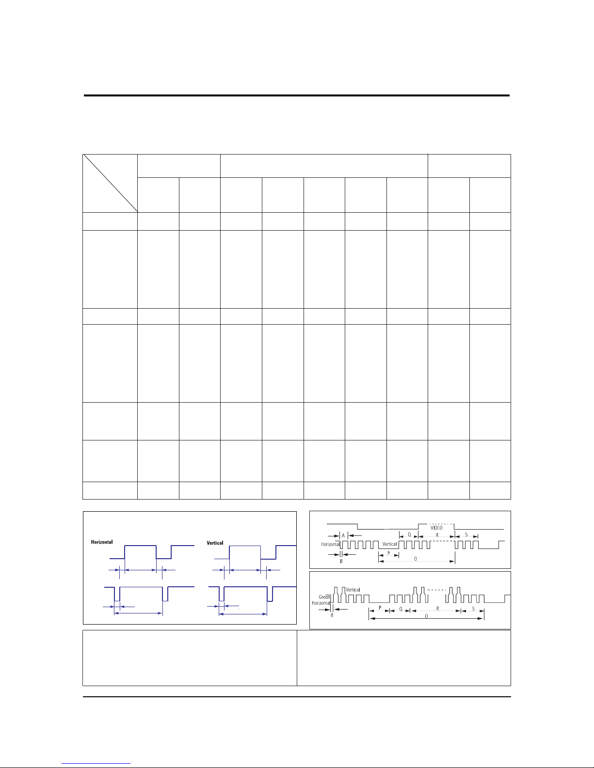
2-4 Timing Chart
This section of the service manual describes the timing that the computer industry recognizes as standard for
computer-generated video signals.
C D
A
O
E
B
P
Video
Sync
Sync
Video
Q R S
A : Line time total B : Horizontal sync width O : Frame time total P : Vertical sync width
C : Back porch D : Active time Q : Back porch R : Active time
E : Front porch S : Front porch
H/V Composite Sync
Sync-on-Green
79.975
12.504
1.067
1.837
9.481
0.119
75.025
13.329
0.038
0.475
12.804
0.013
135.000
Positive
Positive
Separate
1280/75 Hz
1280x1024
1280/60 Hz
1280x1024
63.981
11.852
1.037
2.296
9.259
0.000
60.020
16.005
0.047
0.594
15.630
0.016
108.000
Positive
Positive
Separate
31.469
31.777
3.813
1.589
26.058
0.318
70.087
14.268
0.064
0.858
13.155
0.191
28.322
Negative
Positive
Separate
fH (kHz)
A µsec
B µsec
C µsec
D µsec
E µsec
fV (Hz)
O msec
P msec
Q msec
R msec
S msec
Clock
Freq.
(MHz)
Polarity
H.Sync
V.Sync
Remark
IBM
640/75 Hz
640x480
800/60 Hz
800x600
800/75 Hz
800x600
1024/60 Hz
1024x768
1024/75 Hz
1024x768
VGA2/
70 Hz
720 x 400
VGA3/
60 Hz
640 x 480
Table 2-1 Timing Chart
31.469
31.778
3.813
1.589
26.058
0.318
59.940
16.683
0.064
0.794
15.761
0.064
26.175
Negative
Negative
Separate
37.500
26.667
2.032
3.810
20.317
0.508
75.000
13.333
0.080
0.427
12.800
0.027
31.500
Negative
Negative
Separate
37.879
26.400
3.200
2.200
20.000
0.000
60.317
16.579
0.106
0.607
15.840
0.0261
40.000
Positive
Positive
Separate
46.875
21.333
1.616
3.232
16.162
0.323
75.000
13.333
0.064
0.448
12.800
0.021
49.500
Positive
Positive
Separate
48.363
20.677
2.092
2.462
15.754
0.369
60.004
16.666
0.124
0.600
15.880
0.062
75.000
Negative
Negative
Separate
60.023
16.660
1.219
2.235
13.003
0.203
75.029
13.328
0.050
0.466
12.795
0.017
78.750
Positive
Positive
Separate
Mode
VESA(MJ17AS*/MJ17BS*/
MJ19AS*/MJ19BS*/MJ19ES*/MJ19US*/MJ19QS*)
VESA
(MJ15AS*/MJ15BS*/MJ17AS*/MJ17BS*/MJ19AS*/MJ19BS*/MJ19ES*/MJ19US*/MJ19QS*)
Timing
3 Disassembly and Reassembly
3-1
3 Disassembly and Reassembly
This section of the service manual describes the disassembly and reassembly procedures for the
MJ15AS*/MJ17AS*/MJ19AS*/MJ15BS*/MJ17BS*/MJ19BS*/MJ19ES* TFT-LCD monitors.
WARNING: This monitor contains electrostatically sensitive devices. Use caution when handling
these components.
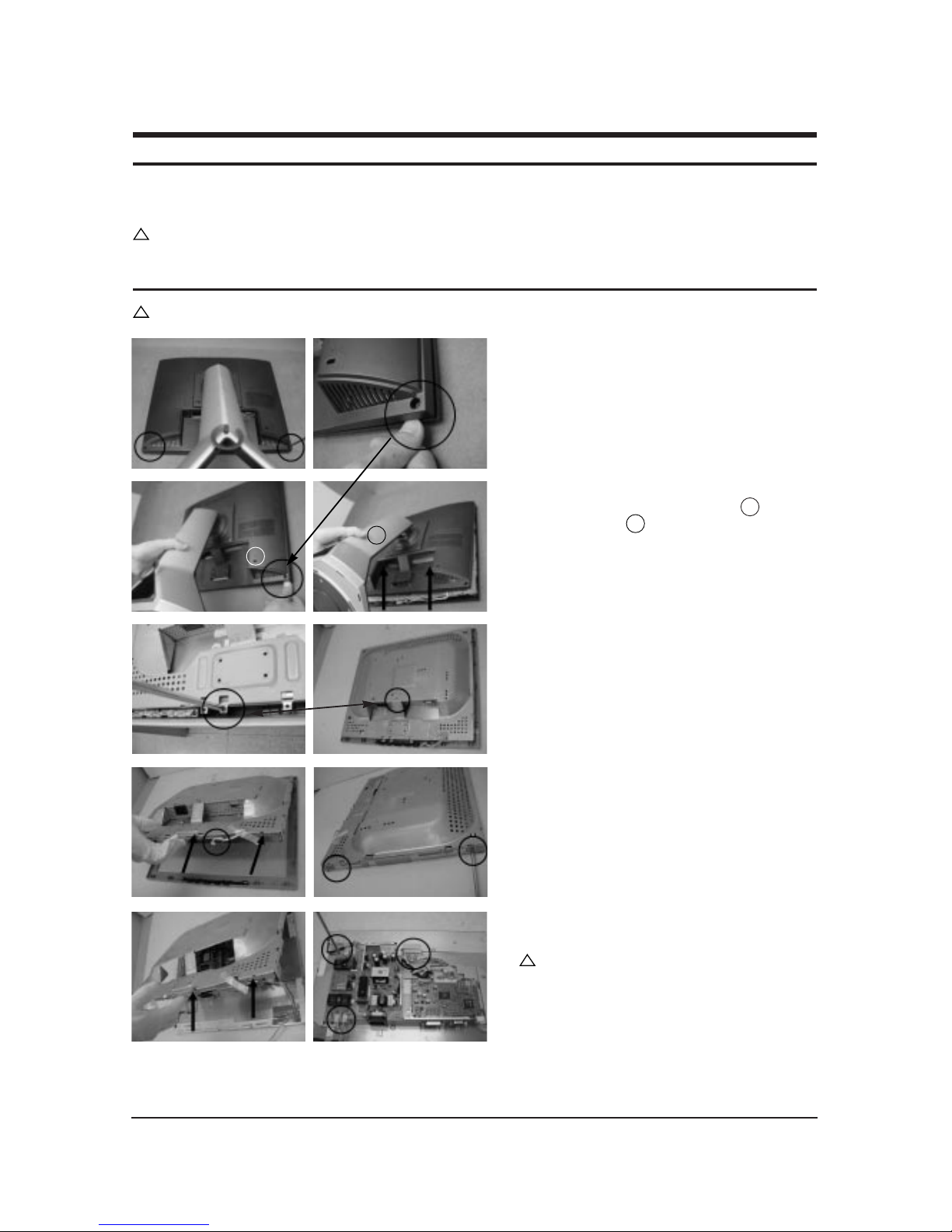
3-1 Disassembly
Cautions: 1. Disconnect the monitor from the power source before disassembly.
1. After placing monitor on the cushioned table,
remove two screws on the left and right of the
bottom.
2. Disconnect back cover from monitor after
grabbing the right edge of the set ( ) and
lifting the stand( ).
3. Remove 2 screws from the shield.
4. Disconnect function cable from the cover front
and lift up the panel. Remove 4 screws from
the panel shield. (Right / Left)
5. Lift up the panel shield and carefully remove
the silicon glue on the cables with a nipper.
Caution : Lamp wire may be easily damaged.
Please use caution when removing the silicon.
!!!
1
1
2
2
3 Disassembly and Reassembly
3-2
6. Remove 7 screws, 4 hexa screws from the boards
and lift up the boards.
Caution : When repairing panel only,
disconnect just LVDS cable, Panel-Lamp /
Wire marked in circle in the picture without
removing the screws on board in order to lift
the board up.
7. This picture is panel.
!
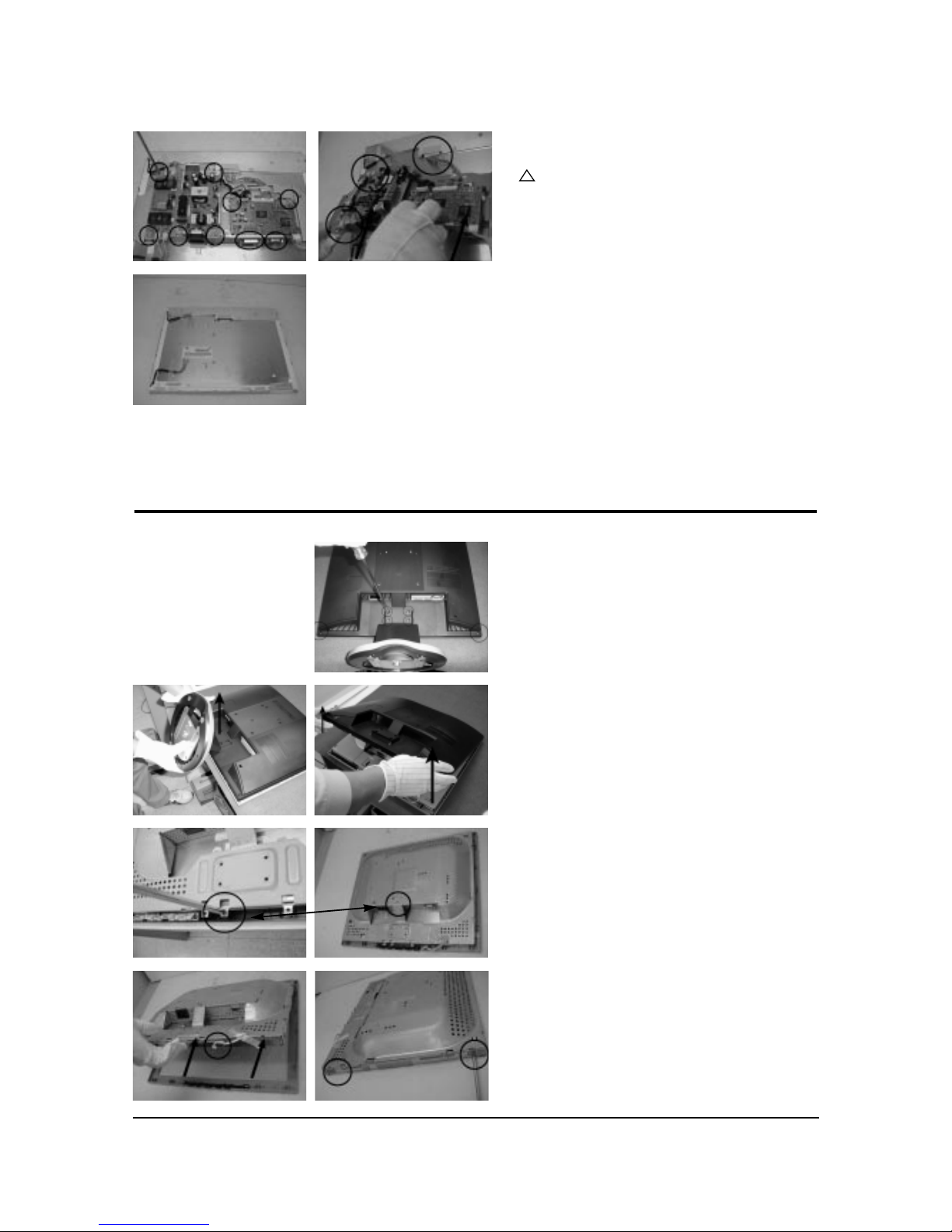
3-2 MJ19ES*/MJ19BS*/MJ19US*/MJ19QS* Disassembly
1. After placing monitor on the cushioned table,
remove 6 screws on the left and right of the
bottom.
2. Lift the stand and lift up the back cover.
3. Remove 2 screws from the shield.
4. Disconnect function cable from the cover front and
lift up the panel. Remove 4 screws from the panel
shield. (Right / Left)
3 Disassembly and Reassembly
3-3
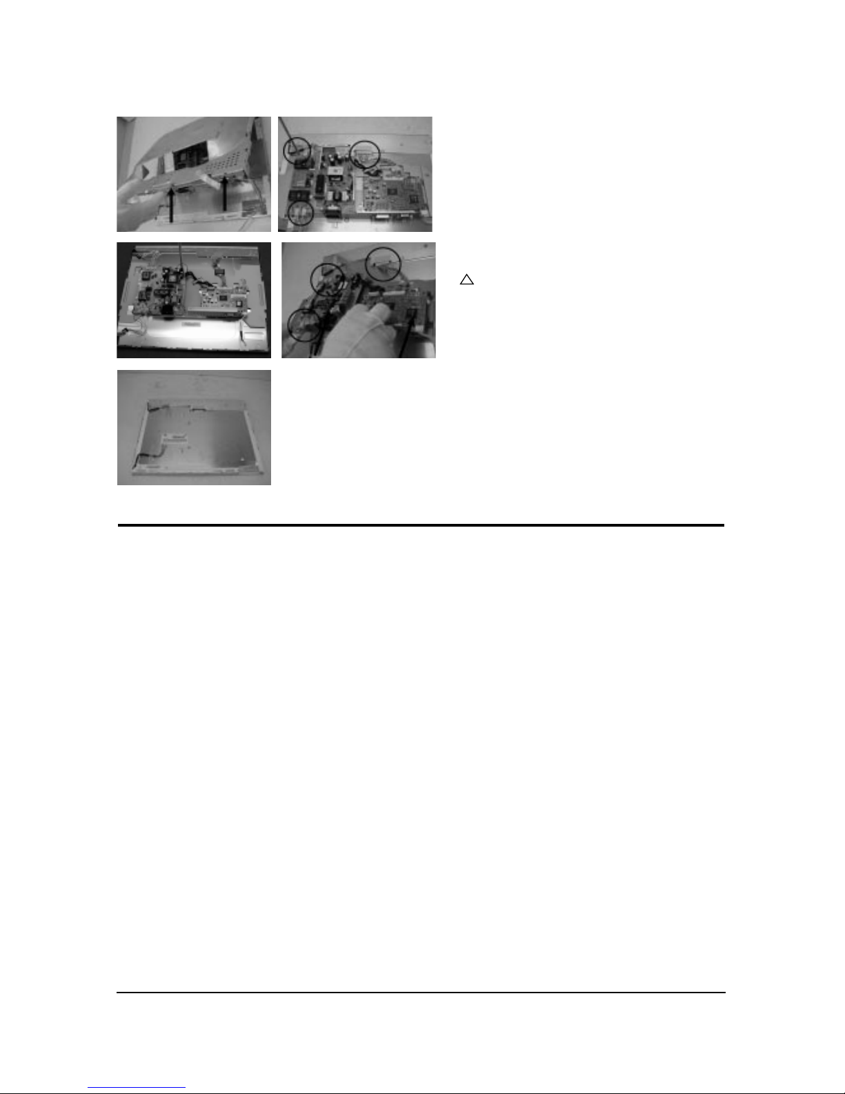
3-2 Reassembly
Reassembly procedures are in the reverse order of disassembly procedures.
5. Lift up the panel shield and disconnect cables.
6. Remove 5 screws, 2 hexa screws from the boards
and lift up the boards.
Caution : When repairing panel only,
disconnect just LVDS cable, Panel-Lamp /
Wire marked in circle in the picture without
removing the screws on board in order to lift
the board up.
7. This picture is panel.
!
4 Alignments and Adjustments
4-1
4-1 Required Equipment
The following equipment is necessary for adjusting the monitor:
• Computer with Windows 95, Windows 98, or Windows NT.
• MTI-2031 DDC MANAGER JIG
4-2 Automatic Color Adjustment
To input video, use 16 gray or any pattern using black and white.
1. Select english for OSD language.
2. Press the “ (Enter/Source)” key for 5 seconds.
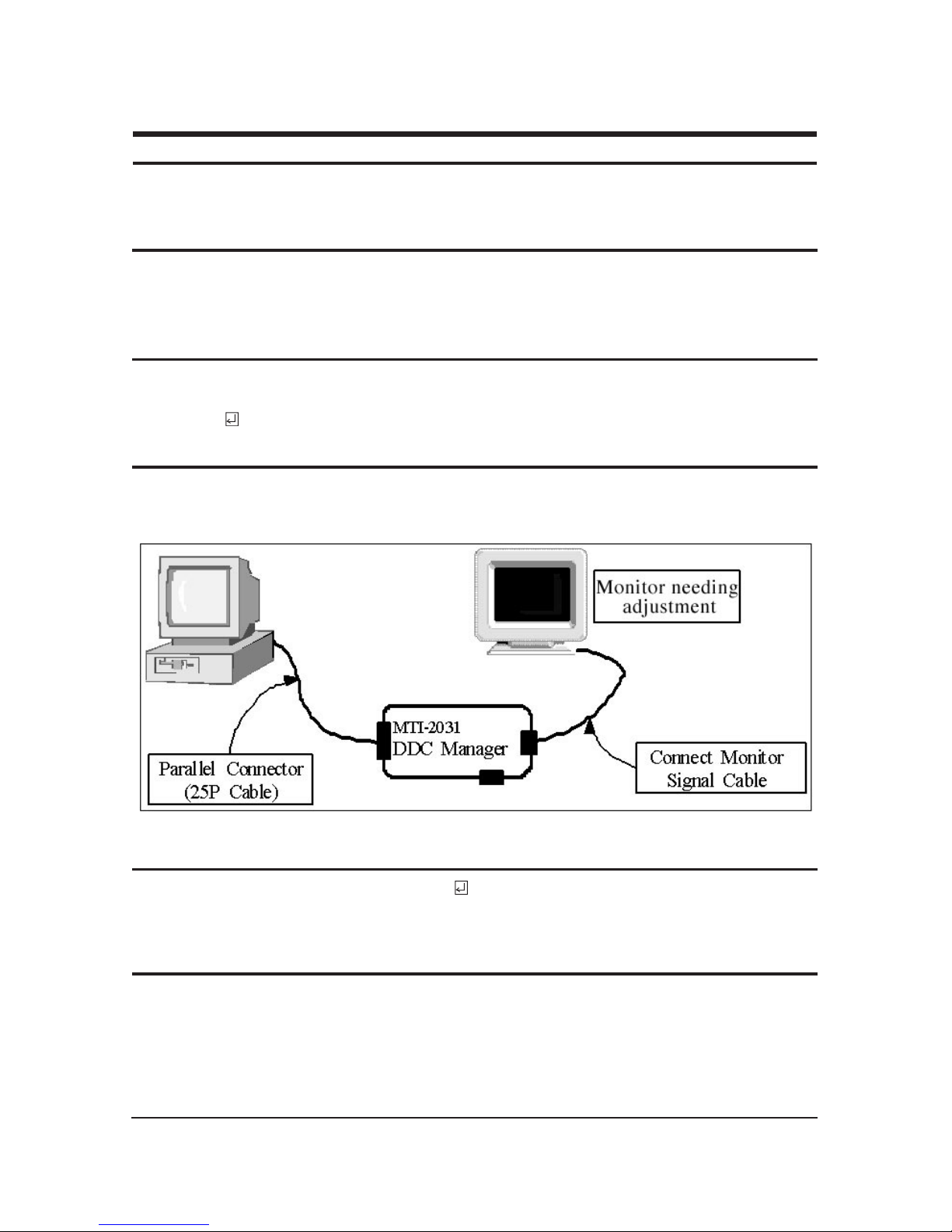
4-3 DDC EDID Data Input
1. Input DDC EDID data when replacing AD PCB.
2. Receive/Download the proper DDC file for the model from HQ quality control department.
Install the below jig (Figure 1) and enter the data.
4-4 OSD Adjustment When Replacing Panel
1. Adjust brightness and contrast to 0. Then, press the (Enter/Source) key for 5 second.
Service function OSD will appear on screen.
2. Press the + key to place the cursor on the panel. Press the menu key for 5 seconds.
4-5 OSD Adjustment When Replacing Lamp Only
1. Adjust brightness and contrast to 0. Then, press the exit key for 5 seconds.
Service function OSD will appear on the screen.
2. Press the + key. Select upper lamp and press the menu key for 5 seconds.
Then, select lower lamp and press the menu key for 5 seconds.
❇
Note : Please be sure to read the following instructions for details on service function.
4 Alignments and Adjustments
This section of the service manual explains how to use the RS232 JIG.
This function is needed for AD board change and program memory (IC110) change.
Figure 1.
4 Alignments and Adjustments
4-2
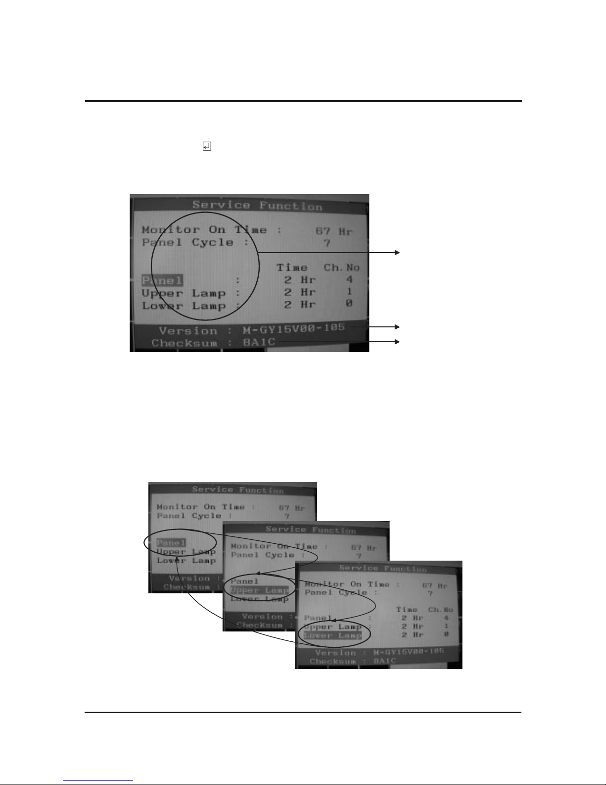
4-6 Ser vice Function Spec.
4-6-1 How to Display Service Function OSD
1. The value for brightness and contrast should be changed to zero.
2. Within 5 seconds, press the (Enter/Source) key.
3. Service function OSD will be displayed.
❇ If you want to disable the service function OSD, you will have to power off.
Figure 2. The example of service function OSD
Figure 3.
Panel Information
Softward Version
Checksum
The service function OSD is based on a grid of 29 columns x 12 rows.
The service function OSD consists of panel information, software version and MICOM checksum.
4-6-2 How to Control Service Function OSD
1. With the panel selected on OSD, whenever you press the right key, the base color will change to blue from
“Panel” to “Upper Lamp”, “Lower Lamp”.
4 Alignments and Adjustments
4-3
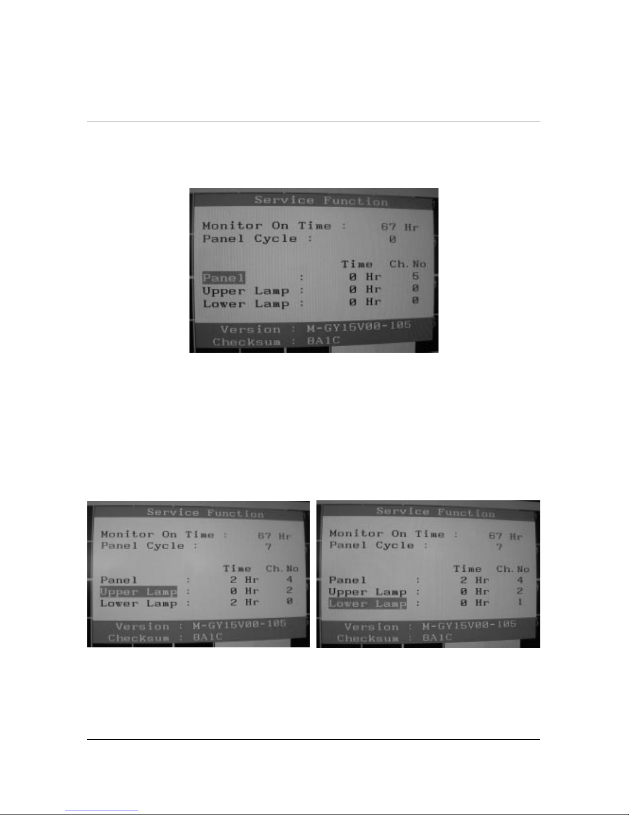
Figure 4.
4-6-3 How to Control Service Function OSD
•After change the panel or lamp, you must reset service function OSD.
•The case of panel change
After changeing the panel, press the menu key within 5 seconds,.
Then, panel Ch. No increases one step and the panel time information is reset to zero.
Simultaneously, other information is reset to zero (Upper/Lower lamp, Panel cycle).
Figure 5, 6.
4-6-4 How to Control Service Function OSD
•In the case of Upper Lamp or Lower Lamp change
After changeing the Upper Lamp or Lower Lamp,
1. Select the Upper Lamp or Lower Lamp
2. Press the Menu key within an 5 seconds.
Then, Ch. No and time will be reset to zero (selected item only).

4 Alignments and Adjustments
4-4
Memo
 Loading...