

Samsung 6100 Series, UN40ES6100, UN46ES6100, UN55ES6100, UN60ES6100 User Manual
LED TV
SERIES[§
6100
#
#
0
1
0
user
~
....
#~
•
manual
Thank
To
your
www.samsung
Model
~
If
yo
u have any ques
you
rec
e
ive
product at
_ _ _
ti
ons,
pl
for
mor
ease
pur
c
ha
s
ing
this
e
compl
e
te
servic
.com/register
__
Serial
ca
ll
us at
1-800-S
Samsung
e,
pleas
No.
____
AM
S
UN
G
produ
e
regist
(1-
800-
c
er
_
726
t.
-7864)
fo
r assistanc
e.
User's
detailed
A
and
Figures
specifications
Manual
ustrations
ill
be
may
built
is
this
in
changed
your
1nto
User
without
1V.
Manual
notice.
For
are
information
more
provided
reference
for
about
how
only
to
and
view
may
this
differ
e-Manual
actual
from
see
page
product
33.
appearances.
Product
design
and
screen
Wide
video.
motion
feature,
this
format
standard
Additionally,
patterns,
and
LED
of
aging
display
primarily
different
view
about
careful
Be
burned
as
well
SAMSUNG
•
Subject
products,
United
the
in
warranty
above
The
Warranty
Center
encountered
Excluded,
replacements,
the
For
the
In
-
Canada
In
-
LED
format
images
The
images
the
with
television
other
viewing
be
should
that
Displays
screen
full
as
formats
television
the
images,
in
ELECTRONICS
requirements,
the
to
the
and
States
originally
period
described
Statement
responsibility
the
is
normal
in
not
but
accessories,
of a
location
States
United
800-SAMSUNG
1-
:
(with
Displays
displayed
constantly
and
video
stationary
described
as
limited
subtle,
leave
images,
ng
i
mov
screen
full
a
formats
covered
not
are
NORTH
requirements,
limited
conditions,
SAMSUNG
on
specified,
repairs
warranty
dated
a
and
the
of
the
of
use
are
to,
options
SAMSUNG
1-800-SAMSUNG
:
Important
aspect
16:9
should
them
on
motion.
in
programming,
tex1
and
mages
i
above
permanent
but
stationary
not
picture
and
select
you
your
by
AMERICAN
exclusions
exclusions
ons,
iti
cond
Bill
purchaser.
product.
any
Author
purchased
products
the
to
and
be
must
as
Sale
of
Conditions
ginally
i
or
upgrades
,
Service
zed
i
(1-800-726-7864)
Warranty
the
ratios,
primarily
Displaying
be
should
as
such
televisions.
all
for
burned-in
patterns
length
the
Samsung
LIMITED
and
Purchase
Original
performed
of
Proof
specified
consumables.
or
,
Center,
Information
screen
the
of
ratio
wide
he
t
in
be
graphics
onary
i
stat
limited
stock
of
limited
WARRANTY
limitations
limitations
and
Canada,
in
by
chase
Pur
covered
provisions
please
Still
more
no
to
reports,
market
Displaying
images
ghost
bars.
dark
or
you
time
warranty.
STATEMENT
the
of
contained
and
only.
r
SAMSUNG
a
must
are
for,
limited
in-home
call
be
toll-free:
image warning
width
screen,
and
than
stationary
the
in
On
them
view
original
Canada
in
Authorized
presented
only
16:9
images
5%
video
LED
LED
.
Limited
herein,
manufac
to
on-srte
or
ght)
i
he
to
io
rat
on
the
of
game
images
cture
pi
mode
ven
Une
Warranty
SAMSUNG
SAMSUNG
on
Service
the
to
services,
format,
ls
Regarding
designed
primarily
are
expanded
or
such
,
screen
the
television
total
displays,
that
To
.
offer
that
aging
LED
Center.
Service
uring
t
station
exceed
this,
avoid
picture
as
supplied
additionally
will
products
Along
Center.
defects
minimum
view
the
a
with
in
view
to
screen,
the
fill
to
sidebars
dark
the
as
week.
per
ng
i
sites
web
,
logos
guidelines
ve
abo
programming
the
vary
eatures,
f
ing
iz
s
rmat
fo
of
sult
re
Samsung
provide
Statement,
is
th
th
or
maximum
in
workmanship,
purchased
wi
Transportation
material
or
screen
wide
if
computer
or
can
these
use
selection
Electronics
Warranty
United
the
the
from
and
to
times,
repair
format
model
your
non-expanded
on
graphics
nev
u
cause
ages
im
and
contro
use,
and
(SAMS
Repair
for
,
States
l
na
gi
i
Or
Serv
the
only
and
exchanges
full-
offers
en
and
,
to
ls
as
G)
UN
Service
e
th
Limited
ce
i
hose
t
or
Avoid
programs
or
affect
Avoid
•
Alway
•
Reduce
•
Use
•
displaying
in
qua
image
displaying
try
s
brightness
features
aii1V
images
still
panorama
reduce
To
.
ity
l
the
display
to
and
designed
or
sa
any
me
as
(such
image
4:3
risk
channel
1V
image
contrast
to
peg
j
format
this
of
full
in
to
reduce
picture
effect,
for
screen.
avoid
image
files)
the
on
please
periods
long
Us
appearance
the
retention
still
,
screen.
follow
the
e
el
image
Constantly
recommendations
the
.
picture
et's
s
1V
after-
of
screen
and
ements
displaying
images.
burn
(such
format
Refer
.
1V
as
still
below
menu
to
channel
pictu
for
e-Manual
the
:
the
res
logos,
can
bes
cause
po
t
for
stock
image
ible
ss
details.
news
or
burn-in
match.
bars
on
at
the
the
screen
LED
bottom
screen
which
,
etc.),
will
•
SMART
HUB: Your gateway to
all
your content, integrated in one place.
- Provides diverse entertainment choices.
- Lets you control your entertainment life with
List of Features
an
easy-to-use, user friendly user interface.
- Gives you easy access to diverse apps, with more being added every
ts
- Le
• AIIShare Play: Lets you
you customize your TV by grouping and sorting apps to your taste.
ac
cess, view, or play photos, videos, or music located on USB devices,
da
digital cameras, cell phones, and PCs. PCs and cell phones can be accessed wir
wireless network.
all
• Anynet+ (HDMI-CEC): Allows you to control
un
with your Sams
g TV's remot
e.
connected Samsung devices that support Anynet+
• e-Manual: Provides a detailed, on-screen user's manual that's built into your
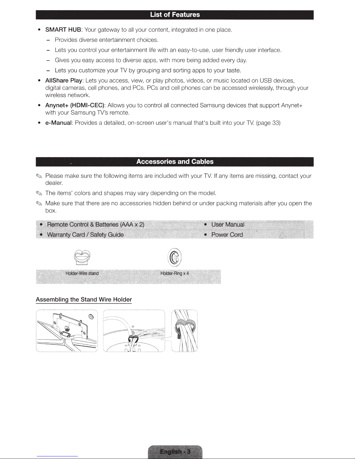
. Accessories and Cables
~
Please make sure the following items are included with your T
dealer.
~
Th e items' colors and shapes may vary depending on the mode
~
Make sure that there are
no
accessories hidden behind or un der p
box.
V.
If any items are missing, contact your
l.
acking mater ia
y.
el
essly,
TV. (page
ls
through your
33)
after you open the
Assembling the Stand Wire Holder
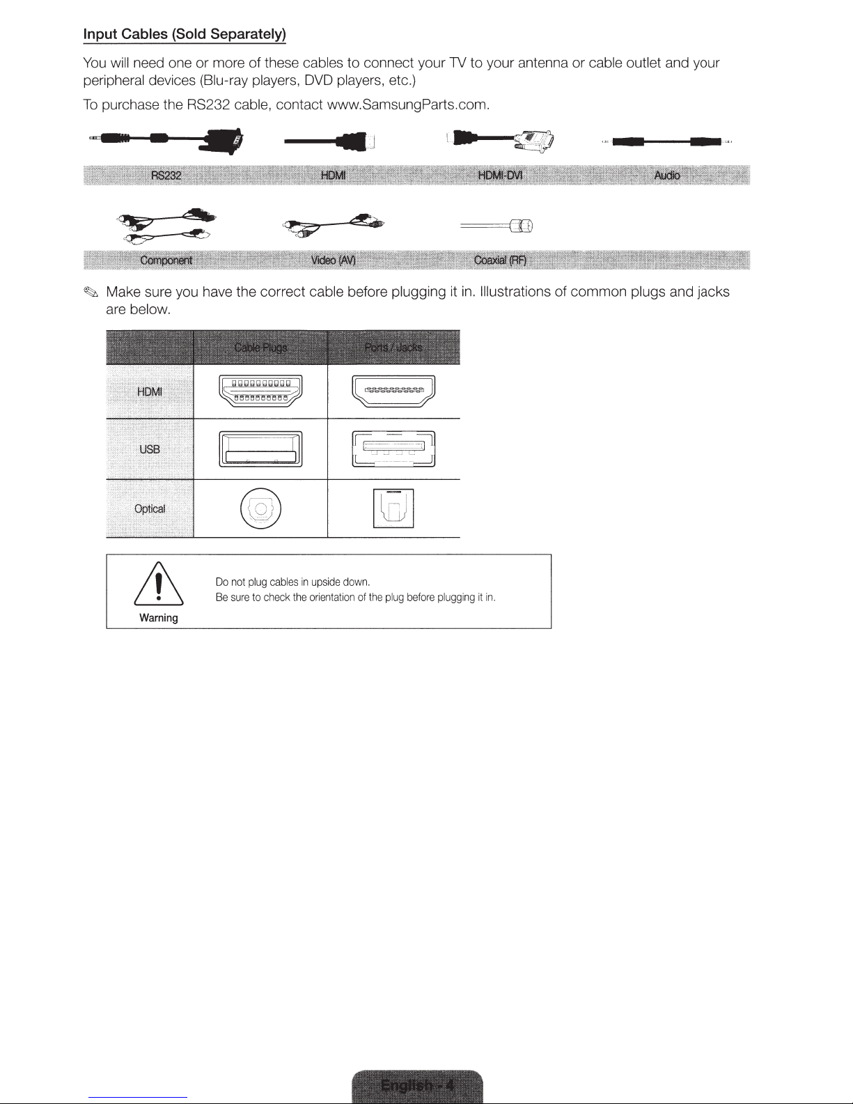
Input Cables (Sold Separately)
You
will need one or more
peripheral devices (Biu-ray players, DVD players, etc.)
To
purchase the RS232 cable, contact www.SamsungParts.com .
of
these cables
to
connect your TV
..
-
~
~
-·~
~
Make sure you have the
are below.
_)
"'
-----
cor
rect cable before plugging it
to
your antenna or cable outlet and your
in.
Illustrations
of
common plugs and jacks
Warning
Do
not
plug cables
Be sure
to check the orientation of the pl
in upsi
~
L.~--
de
dow
·--····-~
~-~
-~~
n.
ug
before plugging it in.
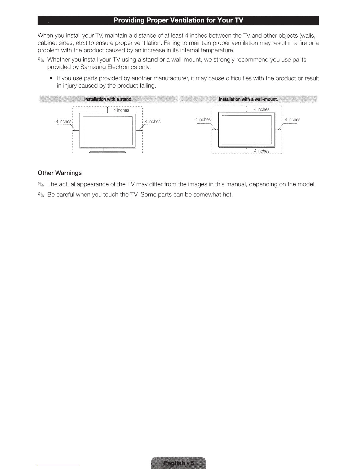
Providing Proper Ventilation for Your
TV
When you install your
cabinet sides, etc.) to ensure proper ventilation. Failing to maintain proper ventilation may result
problem with the product caused by
~?~
Whether you install your TV using a stand
provided by Samsung Electronics o
•
If
you use parts provided by another manufacturer, it may cause difficulties with the product or resu
in
injury caused by the product falling.
4 inches:
~
Other Warnings
~~
The actual appearance
~
Be careful when you touch the
TV,
maintain a distance of at least 4 inches between the
an
increase in its internal temperature.
or
a wall-mount, we strongly recommend you use parts
nly.
[ ----
4inches
I : 4
inches
I~
I :
of
the TV may differ from the images
TV.
Some parts can be some what hot.
; : 4 inch
~-
, i
'
'
: 16:1
:
_______
in this
TV
and other objects (walls,
-~---
~
---~ -J
--
~~J~~ties
----
~
~
;;;;;;;;;;;;;;;;;;;;;;;;;;;;;;;;
manual, depending on the model.
___
;;;;;;;;;;;;;;;;;;;;;;
__
_I_
__
;;;:;d)
4_i~~~e
_
s
__
__
~
in
a fire or a
es
lt
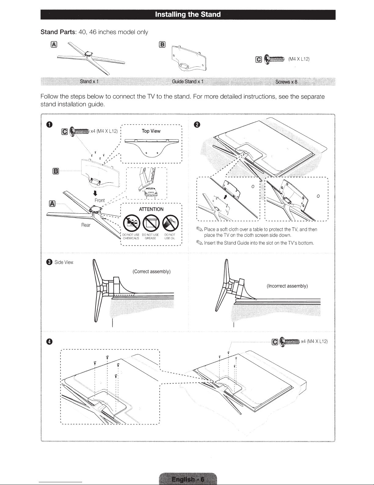
Installing the Stand
Stand Parts: 40,
46
inches model only
Follow the steps below
stand installation guide.
0
·
----
to
connect the TV
[g~
to
the stand. For more detailed instructions, see the separate
(M4XL12)
E)
SideVi
'
.
.
""
"'
ew
.........
Rear
... ...
....
_ ,
-
~
_____
®A@N~:
~
:
DO
NOT
USE
CHEMI
' .
\,.
.. .. _ .............
DO NOT USE 00 NOT I
CAlS
GRE
........... .....
(Correct
....
.. ..
ASE
....................
assembly)
...
..
..
USF 0 1i :
. -.
.....
'*
.
-.
.
-.
Place a soft
place
~
Insert the
the
cloth
TV
on the cl
Stand
----------.
over
Guide
a t
able
oth
scre
en side
into the slot
to protect
the
TV, and then
down
on
the
TV's
bottom.
(
Incorrect
--
assembly)
{lj~x4(M4X
L12
)
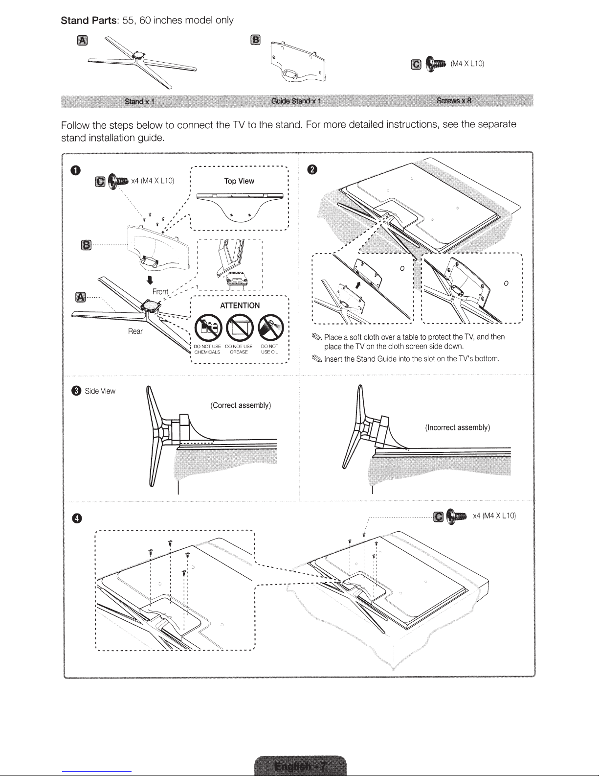
Stand
Parts: 55,
60
inches
model only
fl}
8-
(M4
XL
10)
Follow
the steps below
stand installation
0
t-
llj
••
•
"'"'
View
Side
8
the stand. For more detailed
connect the TV
to
to
guide.
---,
,------- ---- --
x4
(M4
0)
L1
X
,'
Top
ATIENTION
-~®@)~
DO
USE
NOT
00
1
HEMICALS
C
.......
........
~
(Correct
----
View
DO NOT
NOT USE
GREASE
............................
assembly)
USE
L
OI
,
1
:
.'
~
~
Pl
pl
In
ace
ace
sert
a
the
he
t
soft
TV
oth
cl
on
Stand
instructions, see the separate
and
TV,
the
protect
to
table
a
the
Gu
over
cl
de
1
oth
screen
into
the
slot
side
on
down.
the
TV's
bottom.
then
,------------------------
'
'
'
'
'
' .
'
--------
--
---
---
...........
assembly)
rrect
o
nc
(I
4(M4XL
x
_..
•
10)
~
NOTE
•
Make sure
•
Make sure that at least
•
Stand the product up before you tighten the screws.
down, it may lean
&
Do not insert your fingers into the stand base slot
to
distinguish between the front and
two
people lift
to
one side when you stand it up.
and move the
back
of
of
each component when
1V
.
If
you tighten the screws with the
the
TV
when
installing
assembling
the
them.
1V
lying
stand base.
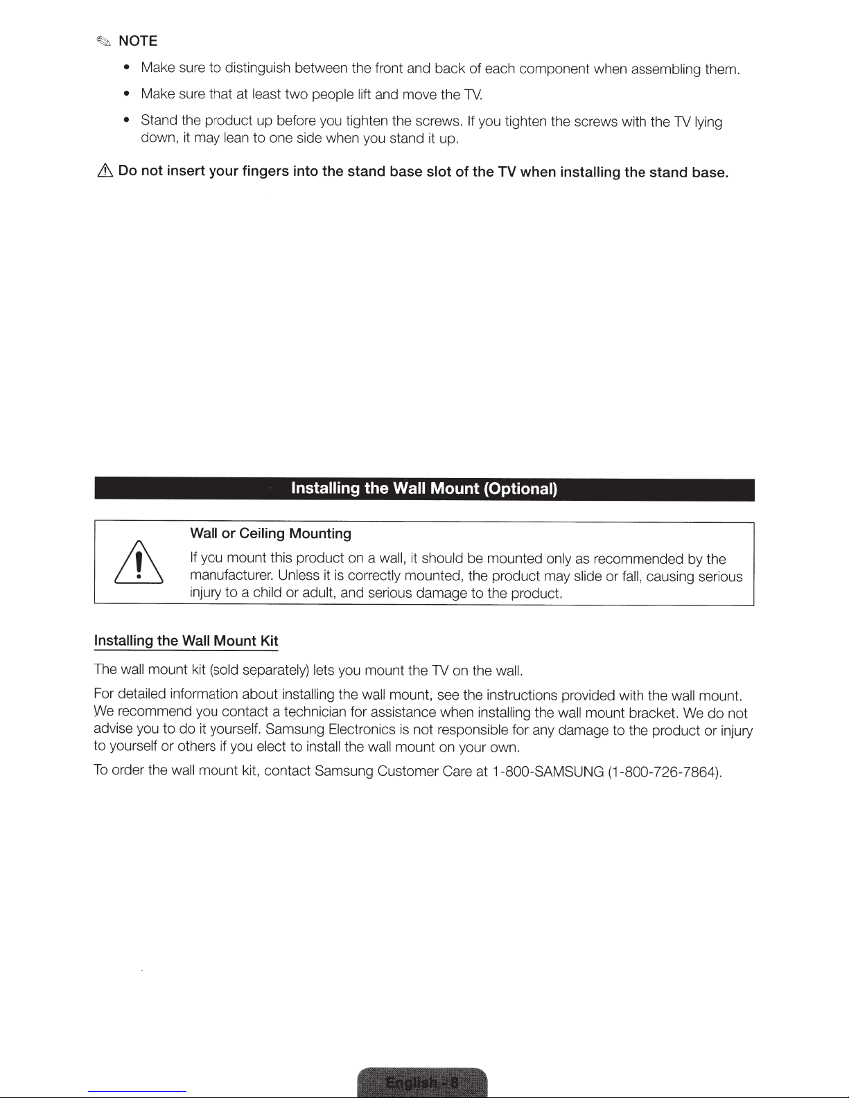
Installing
Wall
or
Ceiling
If
you mount this product on a
manufacturer. Unless it
injury
to
a child
Installing
The
For detailed information abou t
We recommend you contact a technician for assistance wh en
advise you
to yourself or others if you
To
order the
wall
the
Wall
mount kit
to
do
wall
Mount Kit
(sold
separately)
it yourself. Samsung Electronics is not responsible for any damage
mount kit,
Mounting
or adult, and serious damage
lets you mount the
installing
elect
to
install
co
ntact Samsung Customer Care at
is
correct
the
the
the
Wall
Mount
wall,
it should be mounted
ly
mounted, the product may
1V
wall
mount, see the
wa
ll
mount on your own.
on the wall.
(Optional)
only as recommended by the
slide
or
to
the product.
in
structions provided with the
inst
al
ling
the
wall
mount bracket. We
1-800-SAMSUNG
(1-800-726-7864).
fall,
causing serious
to
the product
wa
ll
mount.
do
or
not
injury
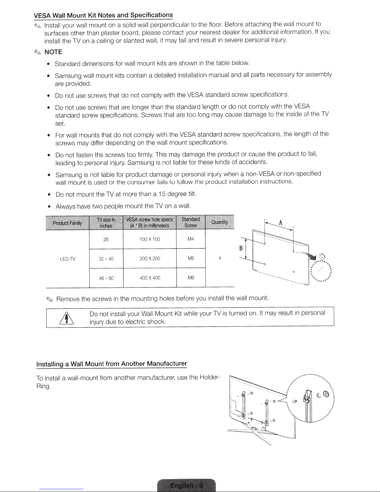
VESA Wall Mount Kit Notes and Specifications
mount on a
Install your
~
wall
surfaces other than plaster board ,
ceiling
mount kits contain a
~
the TV on a
install
NOTE
Standard dimensions
•
Samsung wall
•
solid wall perpendicular
contact your nearest
it may fall and
are
slanted wall,
or
mount kits
wall
for
please
detailed installation manual
are provided.
to the
shown
floor. Before attaching the
additional
for
dealer
and
personal
parts necessary for assembly
all
in severe
result
the table below.
in
mount to
wall
information. If
injury.
you
Do not use screws that
•
Do not use screws that are
•
do
comply
not
longer
with the VESA standard screw specifications .
than the standard
standard screw specifications. Screws that are
set.
mounts that
wall
For
•
do
comply
not
screws may differ depending on the
Do not fasten the screws too
•
injury. Samsung
liable for product damage or
used or the consumer
two
32
people
26
-
mount the TV on a
40
mount
have
TV
-
personal
not
is
is
leading to
Samsung
•
wall
Do not mount the TV at more
•
• Always
LED
with the VESA standard screw specifications, the
wall
This may damage the product or cause the product
firmly.
not
is
fails
100
200
15
0
10
X
200
X
than a
length
long may cause damage
too
mount specifications.
for these kinds of accidents.
liable
personal
follow
to
degree
tilt.
injury when a non-VESA
the product
wall.
M4
M6
4
not
do
or
installation
comply
instructions.
with the VESA
the inside of the TV
to
length
fall,
to
non-spe c
or
ifi
of the
ed
Remove the screws
~
Installing
stall
in
To
Ring.
400
X
46- 60
the mounting
in
install
not
Do
injury due
a Wall
a
Mount from Another Manufacturer
wall-mount from another manufacture
to
400
Wa
your
electric
Mount Kit
ll
shoc
M8
holes before you
your TV
while
k.
use the
r,
Holder-
the wall mount.
install
turned on.
is
It
may
result
personal
in
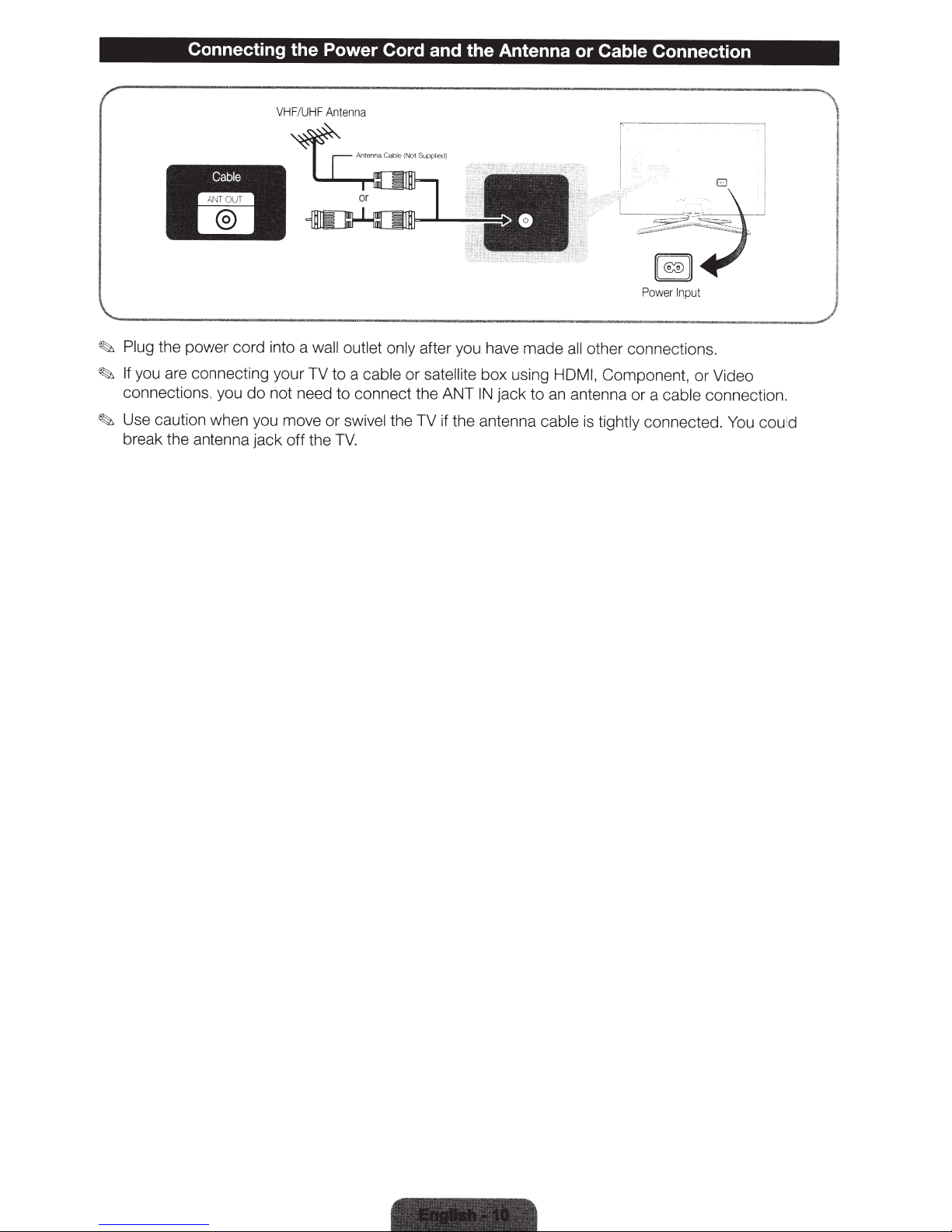
Connecting
VHF
Cable
--
-
~
Plug
the power cord into a
~
If
you are connecting your TV to a
connections, you
~
Use caution wh en you move or
break the antenna jack
do
not need to connect the ANT
the
Power
/
UHF
Antenna
wall outlet only after you have made
off
the
TV.
Cord and the Antenna
cable
or
satellite box using
IN
swivel
the TV if the antenna
jack
to
cable
or
Cable
all
other connections.
HOM
I,
Component,
an
antenna
is
or
tightly connected.
Connection
,,
<>
-··
-
~
'"~
Power
In
pu
t
or
Video
a
cable
connection.
You
.
could
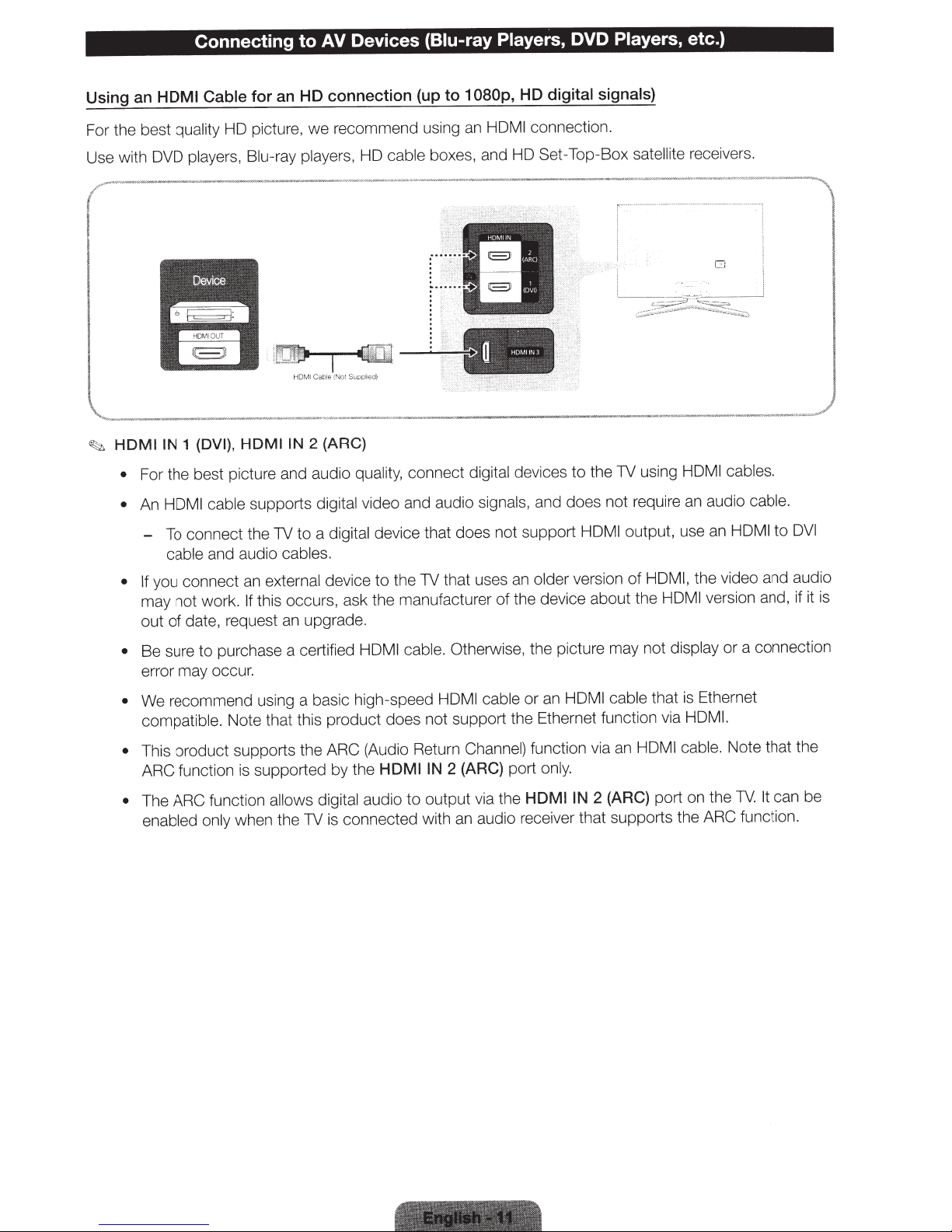
Using an
Devices (Biu-ray
Connecting to
AV
HDMI Cable for an HD connection
Players,
to 1 080p, HD digital signals)
(up
DVD
Players,
etc.)
For the best quality HD picture, we recommend using an HDMI
Use with DVD players,
{DVI),
HDMIIN
~
•
•
1
For the best picture and audio quality, connect digital devices
HDMI
An
connect the TV
To
-
Blu-ray players, HD cable boxes, and HD
~
. .
·
~
:
~-~
t
HDMIIN
I Cab
HDM
2 (ARC)
le
.
·
~,
I
edj
ii
SUiJD
ot
(N
cable supports digital video and audio signals, and does not require an audio cable.
a digital device that does not support HDMI
to
cable and audio cables.
the TV that uses an older version
you connect an external device
• If
this occurs, ask the manufacturer of the device about the HOM
may not work.
If
to
out of date, request an upgrade.
connection.
Set-Top-Box
the TV using
to
satellite receivers.
cables.
HDMI
output, use an
HDMI,
of
HDMI to
the video and audio
version and, if it is
I
DVI
cable. Otherwise, the picture may not display
Be sure
•
purchase a certified
to
HDMI
error may occur.
We recommend using a basic high-speed
•
HDMI
cable that
HDMI
an
or
cable
compatible. Note that this product does not support the Ethernet function via
This product supports the ARC
•
ARC function is supported by the
ction allows digital audio
fun
• The
ARC
enabled only when the
TV
(Audio Return Channel) function via
2 (ARC)
HDMI
connected with an audio rece
is
IN
output via the
to
port
HDMIIN
only.
er that supports the ARC
iv
an
2 (ARC)
Ethernet
is
HDMI.
cable. Note that the
HDMI
port on the
a connection
or
can be
It
TV.
function.
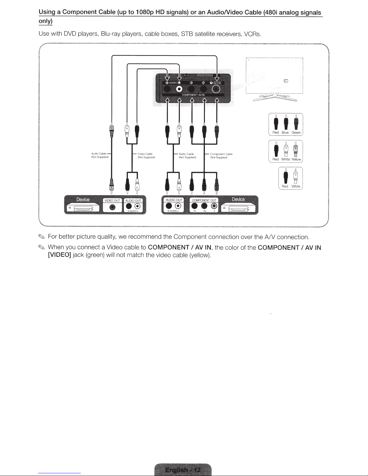
Using a Component
only)
Cable
(up to 1
080p
HD
signals) or an AudioNideo
Cable (480i analog signals
Use with DVD players, Blu-ray players, cable boxes,
STB satellite receivers,
DeVICe
VCRs.
•
It t t
l
Red
Blue
Green )
I
~
For better picture quality,
~
When you connect a Video cable to
[VIDEO]
ja
ck
(gree
n)
we
will
not match the video
recommend the Component connection over the
COMPONENT
cab
I
AV IN,
le (yellow).
the col
or
of th e
COMPONENT
A/V
connection.
I
AV
IN
Connecting
Audio Devices
to
Using an
Use with
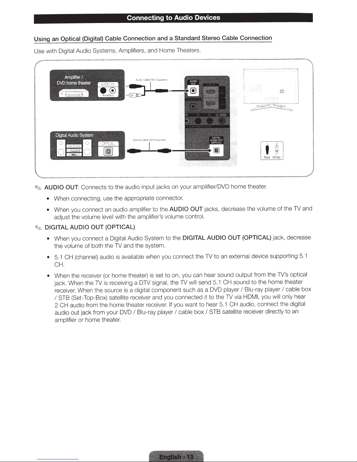
Optical (Digital) Cable
Audio Systems, Amplifiers, and Home Theaters .
Digital
Amplifier/
homeiheater
DVD
,
--~
AUDIO OUT: Connects
~
When connecting, use the appropriate connector.
•
When you connect an audio
•
adjust the
volume level
..._
Connection and a Standard
edl
,
pl
p
Su
QI
Cable IN
A.;rJrc
the audio input jacks on your
to
AUDIO
to the
er
lifi
amp
with the
amplifier's volume control.
Stereo Cable
amplifieriDVD
jacks, decreas e the
OUT
Connection
theater.
home
Whole
Red
volume
the TV and
of
DIGITAL AUDIO
~
When you connect a
•
volume
the
CH (channel)
5.1
•
CH.
When the receiver (or home theater)
•
. When the TV
jack
receiver. When the source is a
STB (Set-Top-Box)
I
CH audio from the home theater receiv
2
audio
amplifier or home theater.
OUT
both the TV and the system.
of
jack from your
out
(OPTICAL)
Digital
avai
is
audio
receiving a DTV
is
satellite
DVD
Audio System to the
when you connect the TV
lable
set to on, you can hear sound output f
is
signal,
component such as a DVD
digital
ceiver and you connected it
re
er.
Blu-ray player
I
DIGITAL AUDIO
the TV
If
will
you want
cable
I
send 5.1
to
hear
to
STB
I
box
(OPTICAL)
OUT
external
an
to
CH sound
player
the TV via
CH audio, connect the
5.1
satellite
device supporting
to
Blu-ray player
I
HDMI,
receiver
jack, decrease
optical
m the TV
ro
's
the home theater
cable
I
you will only
hear
digital
an
directly
to
5.1
box
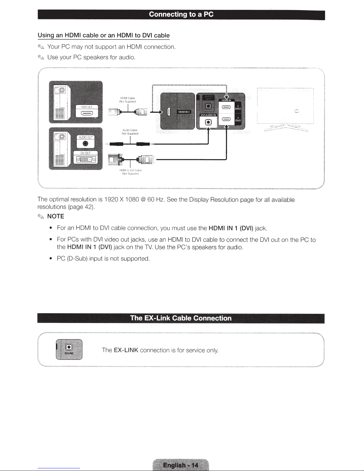
Connecting to a PC
Using an
·'!.:c:t.
~
The optimal
HDMI
Your
PC may not
Use your
cable
PC speakers for audio.
resolution is
resolutions (page 42).
~
NOTE
or
an HDMI
suppor
·
~
1
920
to
t an HOMI
HD
MI Ca
bl
e
(N
ot
Supplied)
Audio
Catwo
X
1
080
DVI
cable
connect
·
-
··
@
60
ion.
~·I
I
II
II
01101111111111111
·
Hz. See the Display
I
lltlllllllllll
11111111111111~
Resolution page for
all
available
I
C::
-
•
For an
• For
the
• PC
HDMI
to
OVI
PCs
with
DVI
video out jacks, use an
HDMI
IN
1 (DVI)
(D-Sub) input is
The
cab
le
co
jack on the
not
supported.
The EX-Link Cable
EX-LINK
nnection, you must use the
HOM I
to
DVI
cable
TV.
Use the
PC's
speakers for audio.
Connection
co
nnection is for se rvice
HDMIIN
to
only.
1
(DVI)
connect the
jack.
DVI
out on the
PC
to

Connecting to a Network
can set up your TV so that it can access SMART
You
using a wired or
(LAN)
After you have
~
connection to complete
process
(see
wireless connection.
"physically"
connected your TV to your
the process. You can configure the connection during the
after the
page 23)
or
Initial Setup
applications through your
TV
configure the network
must
network,
you
process. through the TV's menu
area network
local
Initial Setup
ee page
(s
31)
.
Network Connection -
can connect your TV
You
on
Port
LAN
e
Th
s TV supports the
Thi
you
If
802.11
IEEE
wireless network systems incorporate a security system that requires devices that access the
Most
n.
network through an access point or AP (typically a
called
security
Your TV is
•
• Encryption
If
TKIP
Wi-
code
compatible
Authentication Mode:
Type:
Pure High-throughput (Greenfield) 802.11
select
you
on your AP or
certification specifications.
Fi
Wireless
local
your
to
uter
Ro
IP
eless
ir
the
Wa
LAN
IEEE
play
an
ll
Cable
access
W
Modem
Not
(
802.11
video using
that
Server
Supp
key.
a
has
)
ied
l
a/b/g
IEEE
with the following security
OPEN, SHARED, WPAPSK,
AES
TKIP,
WEP,
wireless router,
Samsung TVs
area network (LAN) through a standard wireless
or
DHCP
and n communication
802.11
a,
g,
b, or
wireless router
protocols.
the video may not
or
Samsung recommends using
play smoothly.
transmit
modem)
to
protocols:
WPA2PSK
and the Encryption type
mode
n
compliance
not support a connection
will
in
router or modem.
encrypted
an
or
WEP
to
set
is
with new

Network Connection - Wired
There a
re
three main ways to conn
setup. They are
T
he
Modem
The
M
ode
m
illu
s
tr
ated starting belo w:
Po
rt
on
the
Wall
M
odem
Po
rt
on
t
he
Wall
Modem
(Not
Supplied)
Cab
Cab
le
(ADS
le
ec
t your
(N
ot
Externa
L
I
VDS
Suppl
l M
L
1V
(ADSL
i
ed)
odem
I
Cab
to
your network using cable, depending on your net
Ex
te
rn
al
M
le
LAN
(
Not
I
TV)
Suppli
V
DS
Cab
L
le
ed)
odem
I
Cab
le
IP
TV)
R
outer
DHCP
LAN
th
Serve
Cab
at
has
r
le
(No
t
Su
pp
li
ed
)
a
LAN
Cab
(N
ot
Suppl
TV
le
ie
d)
TV
work
R
ea
r
Pan
el
Re
ar
Pane
l
~
~
The
Use
T
he
TV
Cat
LAN
Po
does
6
(S
rt
not
TP
on
th
e
support
Ty
pe*)
Wa
ll
cab
network
le for the
LA
N
Cable
(N
ot
Supplied
speeds less th an
co
nnection. (*Shielded Twisted Pa
or
equal to
)
1OM
bps.
ir)
TV
R
ear
P
ane
l
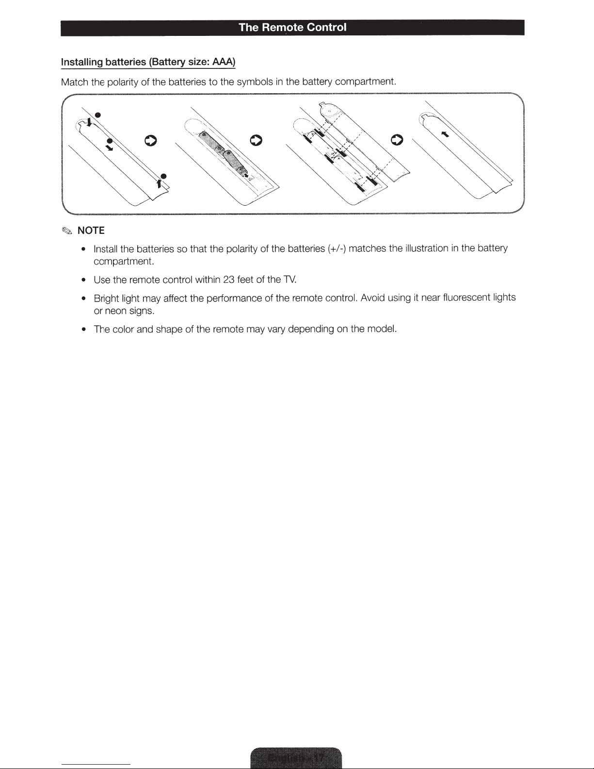
The Remote
Control
Installing
Match
the
---·-.
~
·
(
NOTE
~
• Install
compartment.
Use
•
Bright light
•
or
The color
•
batteries
polarity
(Battery size: AAA)
the batteries
of
to
the
~.
'
that the polarity
the batteries
remote
the
may
neon signs.
and shape
so
control
affect
of
23
within
performance
the
the remote
symbols
of
the
of
feet
of
vary depending on the
may
the battery compartment.
in
matches the illustration
-)
/
the batteries
TV.
the remote
(+
control.
Avoid using it near fluorescent
model.
the battery
in
lights
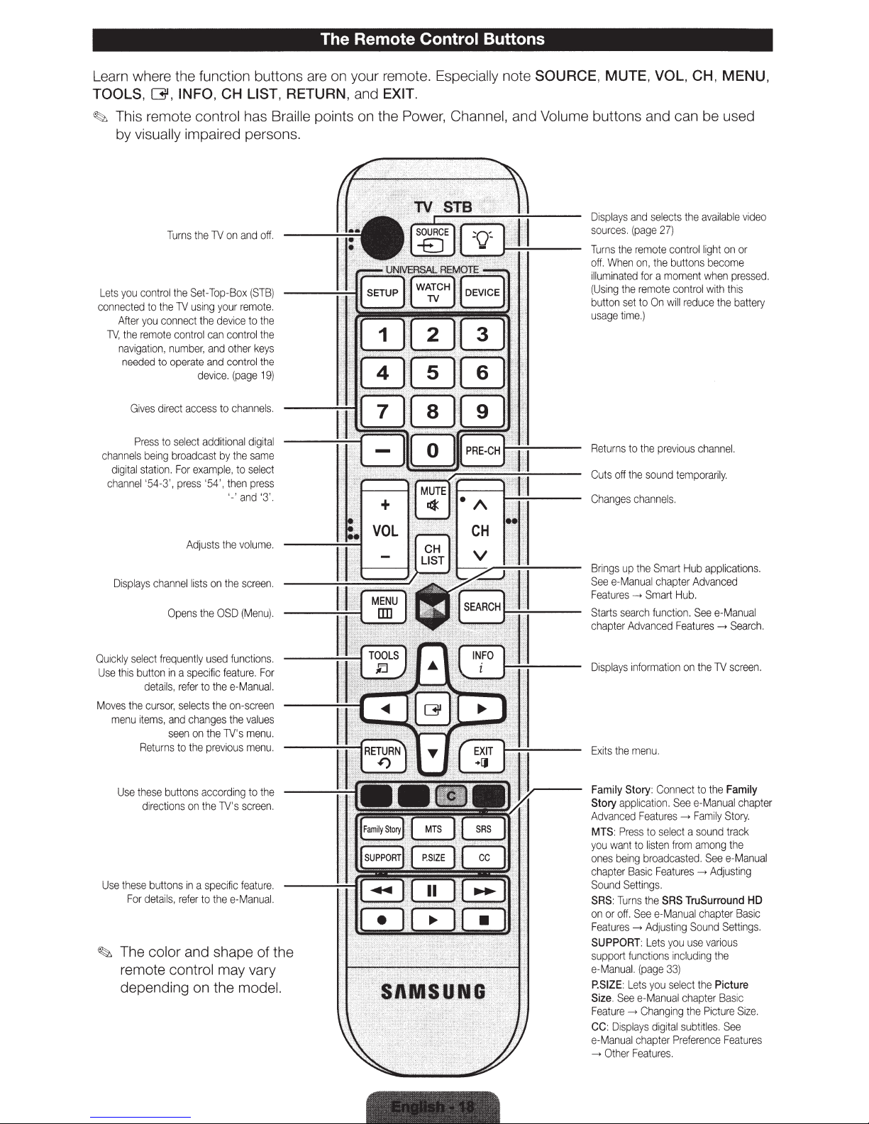
The Remote Control Buttons
Learn where the function buttons are on your remote. Especially note SOURCE, MUTE, VOL, CH, MENU,
G,
TOOLS,
~
This remote control has Braille points on the Power, Channel, and Volume buttons and can be used
by visually impaired persons.
Lets
you
connected
After
TV,
the
navigation
needed
Gi
Pr
c
hannels
di
gital stat
annel
ch
INFO, CH LIST , RETURN, and EXIT.
contro
to the
you
connect
remote
, n
to
ves
direct
ess
to
being
ion. For
'54
-3', press
Turns the
l t
TV
he
Set-Top-Box
TV
us1ng
your
the
con
operate
select
broadcast
device
trol
can
umber,
and
and
device. (page
access
additional
example, to select
'54',
on
and off
rem
contro
other
con
to
channels
by the
then
'-'and '3
(STB)
ote
to the
l t
he
keys
trol the
19)
digital
same
press
.
.
.
'.
1
4
7
2
3
5 6
8 9
Di
spla
ys
and
ces. (p
the
en
set
rns
to
off the
selects
age
remote
on,
the
for a moment
remote
to
On
.)
the
previous
sound tem
sour
Tu
rns
off. Wh
i
lluminated
(Using the
button
usa
ge time
Retu
Cuts
Changes channel
the
27)
control light
buttons bec
control
will
reduce the batt
s.
avail
able
on
ome
when pressed
wit
h th
is
channel.
poraril
y.
or
vid
eo
ery
.
Adjusts
the
volume.
Displa
ys
channel li
sts
on
the scr
Opens the
Ou1ckly
select fre
button
d
etails,
R
eturns
directi
detail
s,
que
in a specific fea
and
seen
ons
ons
s, re
Use this
Moves
the cursor, sel
me
nu item
se these butto
U
U
se these butt
For
~
The color and shape of the
OSD (Menu).
ntly
used
functions
ture.
refer to the e-Manua
ects
the
on-screen
changes the valu
on the TV's me
to
the
previous menu
ns
according
on the
TV's scr
in
a s
pecific
to
the
e-Manual.
feature.
fer
remote control may vary
depending on the model.
een
For
es
nu.
to the
een
Brings
up the
Smart
Hub
.
.
l.
.
.
See e-Man
F
eatures
Starts
hapter Advanced
c
Dis
Exits t
Family Story: C
Story
Adv
MTS
you
on
ha
c
Sound
SRS
on
eatures
F
SUPPORT: Lets you u
sup
e-Manua
P.SIZE
Size See e-Manu
Featu
CC
e-M
___,
ual chapter
-+
Smart
search function.
pla
ys
Information on
he menu.
applicatio
anced Fea
want to listen
es bei
pter Bas
: Tu
or off. See e-Manu
port
: Displ
anual chapt
Other Fe
tur
: Press
to select a
ng
broadcasted.
ic Features
Set
ting
s.
rns the
SRS
__,
Adjusting Sound
function
l. (pa
ge
: Lets
you select the Picture
re
___,
Cha
nging
ays
digit
er Preferen
atures
applications.
Adv
anced
Hub
.
See e-Manua
Features __,
onnect to the Family
n.
See e-M
es
__, Fami
from among the
TruSurround
al ch
s Including
33)
al
chapter
the
al subt
.
the
TV scree
anual cha
ly
sou
nd trac
See e-Ma
__,
Adjusting
apter
se var
ious
the
Basi
Pictur
itl
es.
ce Features
Search.
Story
.
k
HD
Bas
Settings.
c
e S1ze.
See
n.
nua
ic
l
pter
l
Setting up Universal Remote with
~
If your remote controller buttons does not work, please set your remote to
DEVICE button.
To
set
up
1.
2.
To
identify your remote, press and hold the SETUP button for 8 seconds. If you use this function f
Universal Remote, press the SETUP button on your remote.
The
Universal Remote Setup Application
the first time, the END USER LICENSE AGREEMENT screen appears.
3. Press the
button
to
select AGREE. It is required
to
agree with the terms prior to using Universal
G'
Remote.
4. Select a remote control you have. The remote option menu screen appears.
TV
mode by using the
or
5. Select Set up a device
6. Select an external device you want
7. Select a port that the external device is connected
an
cannot find
selecting
8. Select a brand name of
name, select
QWERTY keypad screen. When done, select
a brand name
external device, please check your external device connection, and then try again by
Refresh.
Search brands. The QWERTY keypad screen appears. Input a brand name using the
in
the search result.
to
control. The Select a device screen appears.
to
connect. The Input Source screen appears.
to
the
TV.
The Brand screen appears. If your TV
the
external device you have. The Model screen appea rs.
Done. Wait until the search
To
search a brand
is
completed and then select
9. Select SEARCH MODEL. The QWERTY keypad screen appears. Input a model number in the same
way as Step
model, select
If you select
13.
10. The Test screen appears. Press and hold the SETUP button for 3 seconds. Numbers appears on the
screen.
11. Enter the following numbers using your remote. The button test screen appears.
12. Press the V
the device. If you external device
data, and then the Test screen reappears.
8,
and then select a model number you have
Recommended. The TV progresses a test using the code set of the brand you
Recommended,
CH
A button to test your remote. If your external device working, select YES
go
to Step 11.
is
not work, select NO. If you select NO, the TV changes the code
If
you select a model
Try
again Steps
in
the search result list. If you can't find the
in
the search result list,
10
to
12.
go
to
se
lected.
to
Step
register
~
If all the code data
do
not
work
, please check the brand name or search a model name of your
external device again.
13. Your external device has been setup success
fully.
 Loading...