

Samsung 470, 473, 570, 475, 476 Installation Manual

LED TV
Installation manual
imagine the possibilities
Thank you for purchasing this Samsung product.
To receive more complete service, please register
your product at
www.samsung.com/register
Model Serial No.
470/473/475/476/570
[Hotel-XC]Install Guide.indb 1 2012-11-01 �� 2:23:57
Figures and illustrations in this User Manual are provided for reference only and may differ from actual product appearance.
Product design and specifications may be changed without notice.
Instruction
This TV is provided with interactive functionality through a set-back box (SBB/STB) connected to the TV, and with other TVs in a computer controlled
system for hotels and other hospitality businesses.
Interactive : When the TV is powered-up initially, it sends a command to identify the SBB/STB; if identified, theTV switches to ONLINE mode and full
control is through the SBB/STB.
If the TV is in ONLINE mode, it stops receiving IR(Samsung remote) commands and acts according to interface protocol.
Stand-Alone: If SBB/STB is not identified, the TV should be switched to STAND-ALONE mode with restricted operation.
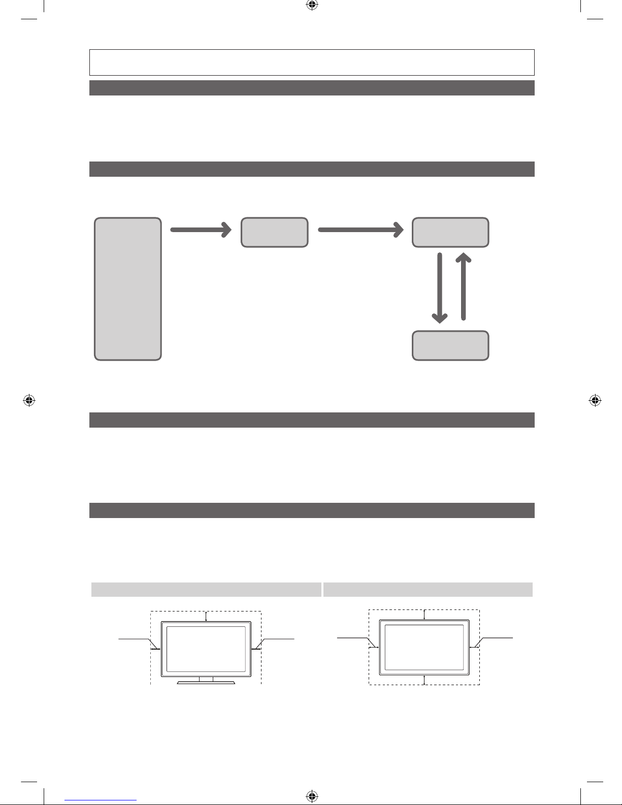
Operational Modes
When this TV (in Hotel mode) is operated with a SBB/STB, it is in one of two states
• ONLINE or STAND-ALONE. In the STAND-ALONE state, the TV will act as a Hotel TV, but without active communication. This is to prevent guests
from trying to cheat the system by disconnecting the SBB/STB.
Power
ON
Hotel TV
Online Mode
Poll Rate 20/sec
Stand-alone
Mode
Hotel Mode On
SBB/STB Online if one
success within 10 attempts
SBB/STB Online-10
consecutive fails
SBB/STB StatusAttempt every
2secs
To set the details for Stand-alone or interactive mode, refer to pages 22-25(Setting the hotel option data : Stand-alone mode and Interactive mode)
• Some operations may be restricted to prevents guests from "cheating" the TV system.
• No main menu(Interactive mode) or Channel Menu, Plug & Play in Main Menu(Stand-Alone mode)
• Limited Volume and Panel key lock or unlock
Still image warning
Avoid displaying still images (like jpeg picture files) or still image element (like TV Program logo, panorama or 4:3 image format, stock or news bar at screen
bottom etc.) on the screen. Constant displaying of still picture can cause uneven wear of screen phosphor, which will affect image quality. To reduce risk of
this effect, please follow below recommendations:
• Avoid displaying the same TV channel for long periods.
• Always try do display any image on full screen, use TV set picture format menu for best possible match.
• Reduce brightness and contrast values to minimum required to achieve desired picture quality, exceeded values may speed up the burnout process.
• Frequently use all TV features designed to reduce image retention and screen burnout, refer to proper user manual section for details.
Securing the Installation Space
Keep the required distances between the product and other objects (e.g. walls) to ensure proper ventilation.
Failing to do so may result in fire or a problem with the product due to an increase in the internal temperature of the product.
✎
When using a stand or wall-mount, use parts provided by Samsung Electronics only.
x
If you use parts provided by another manufacturer, it may result in a problem with the product or an injury due to the product falling.
✎
The appearance may differ depending on the product.
Installation with a stand. Installation with a wall-mount.
10 cm10 cm
10 cm
10 cm10 cm
10 cm
10 cm
[Hotel-XC]Install Guide.indb 2 2012-11-01 �� 2:23:57
3
Contents
ENGLISH
English
y Accessories .............................................................................................................................................................. 4
y Installing the LED TV Stand ....................................................................................................................................... 5
y Viewing the Connection Panel ................................................................................................................................... 6
y Using the TV’s Controller (Panel Key) ....................................................................................................................... 10
y Viewing the Remote Control .................................................................................................................................... 11
y Connecting the TV with SBB ................................................................................................................................... 12
y Connecting the Bathroom Speakers ....................................................................................................................... 14
y Connecting a Pillow Speaker ..................................................................................................................................17
y Connecting the MediaHub HD ................................................................................................................................18
y Connecting the RJP (Remote Jack Pack) ................................................................................................................ 19
y Setting the Hotel Option Data .................................................................................................................................21
y SIRCH ....................................................................................................................................................................31
y Installing the Wall Mount ......................................................................................................................................... 76
y Securing the TV to the Wall ..................................................................................................................................... 77
y Anti-theft Kensington Lock ...................................................................................................................................... 77
y Specifications .........................................................................................................................................................78
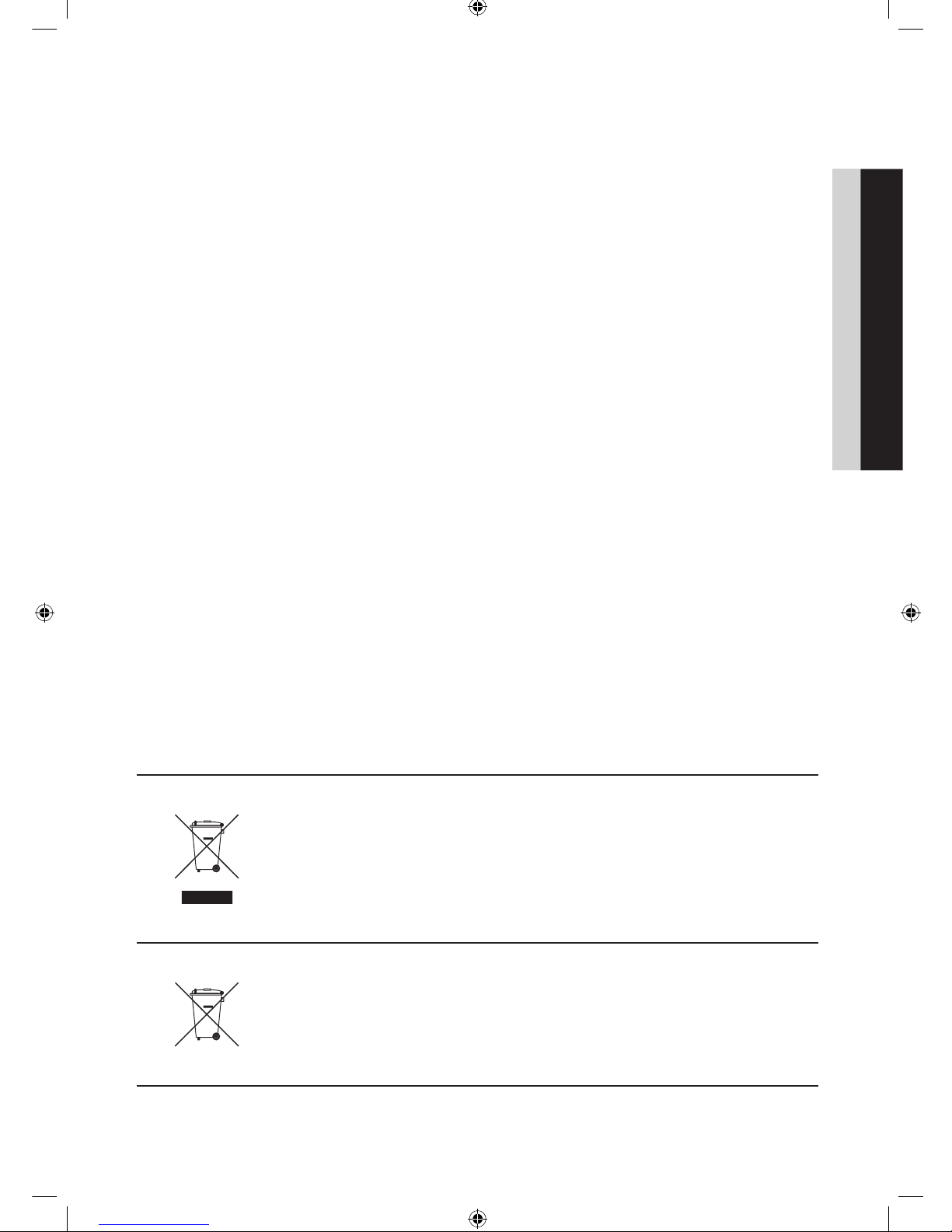
Correct Disposal of This Product (Waste Electrical & Electronic Equipment)
(Applicable in the European Union and other European countries with separate collection
systems)
This marking on the product, accessories or literature indicates that the product and its electronic
accessories (e.g. charger, headset, USB cable) should not be disposed of with other household waste
at the end of their working life. To prevent possible harm to the environment or human health from
uncontrolled waste disposal, please separate these items from other types of waste and recycle them
responsibly to promote the sustainable reuse of material resources. Household users should contact either
the retailer where they purchased this product, or their local government office, for details of where and
how they can take these items for environmentally safe recycling. Business users should contact their
supplier and check the terms and conditions of the purchase contract. This product and its electronic
accessories should not be mixed with other commercial wastes for disposal.
Correct disposal of batteries in this product
(Applicable in the European Union and other European countries with separate battery
return systems)
This marking on the battery, manual or packaging indicates that the batteries in this product should not
be disposed of with other household waste at the end of their working life. Where marked, the chemical
symbols Hg, Cd or Pb indicate that the battery contains mercury, cadmium or lead above the reference
levels in EC Directive 2006/66. If batteries are not properly disposed of, these substances can cause harm
to human health or the environment. To protect natural resources and to promote material reuse, please
separate batteries from other types of waste and recycle them through your local, free battery return
system.
[Hotel-XC]Install Guide.indb 3 2012-11-01 �� 2:23:58
4
English
Accessories
✎
Please make sure the following items are included with your LED TV. If any items are missing, contact your dealer.
✎
The items’ colour and shapes may vary depending on the models.
y Remote Control & Batteries (AAA x 2)
y Quick Set up Guide
y Safety Guide (Not available in all locations)
y Cleaning Cloth
y Power Cord / Data Cable
✎
The stand and stand screw may not be included depending on the model.
✎
The Data Cable may not be included depending on the SI Vendor.
Installing the LED TV Stand
The 32” and larger LED TVs have swivel stands. You can set these stands so that the TVs swivel 20 degrees left and right or
90 degrees left and right. The 26” LED TVs do not have swivel stands.
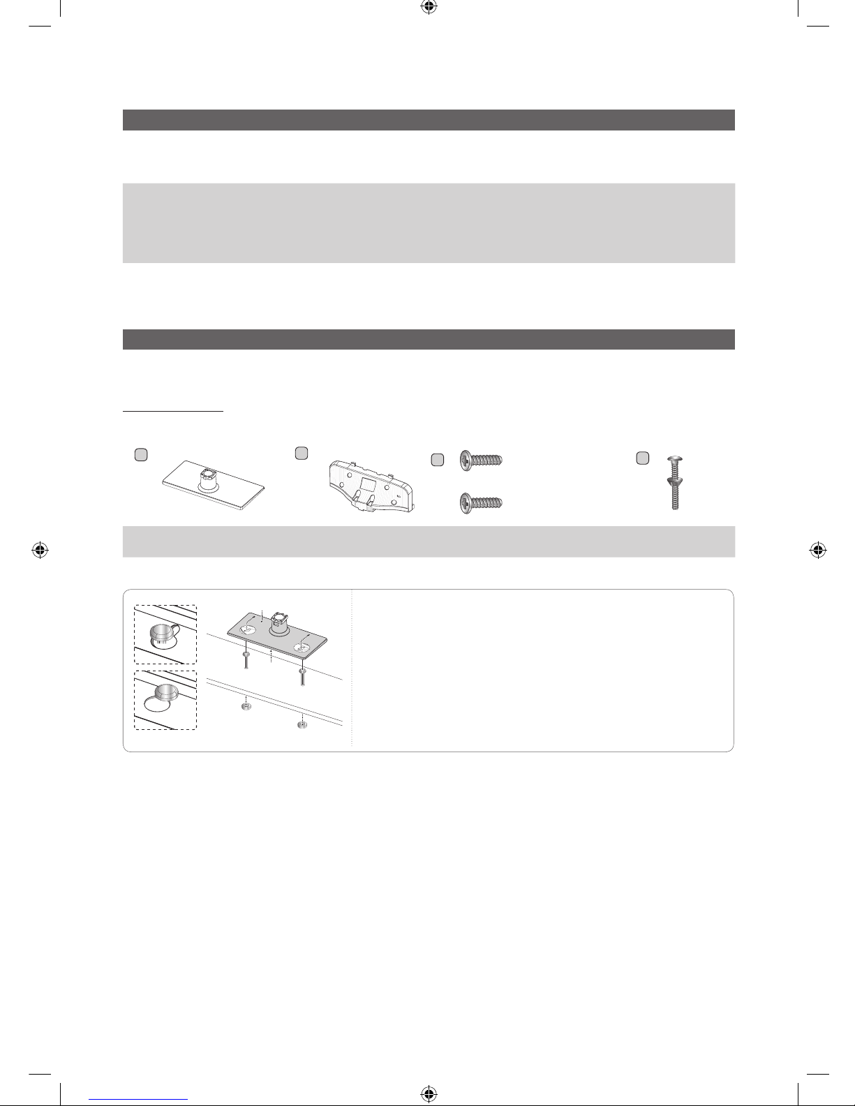
Stand Components
When installing the stand, use the provided components and parts.
A
1 EA
B
1 EA
or
- Security Screw
4EA (M4 X L16)
C
x8 (M4 X L12)
D
y Stand
(depending on the model)
y Guide Stand y Screws
y Bolt + Nut (32 inch only)
32 inch only
]
WARNING: To prevent injury, this apparatus must be securely
attached to the floor/wall in accordance with the installation
instruction.
Bottom
Top
[Hotel-XC]Install Guide.indb 4 2012-11-01 �� 2:24:00
5
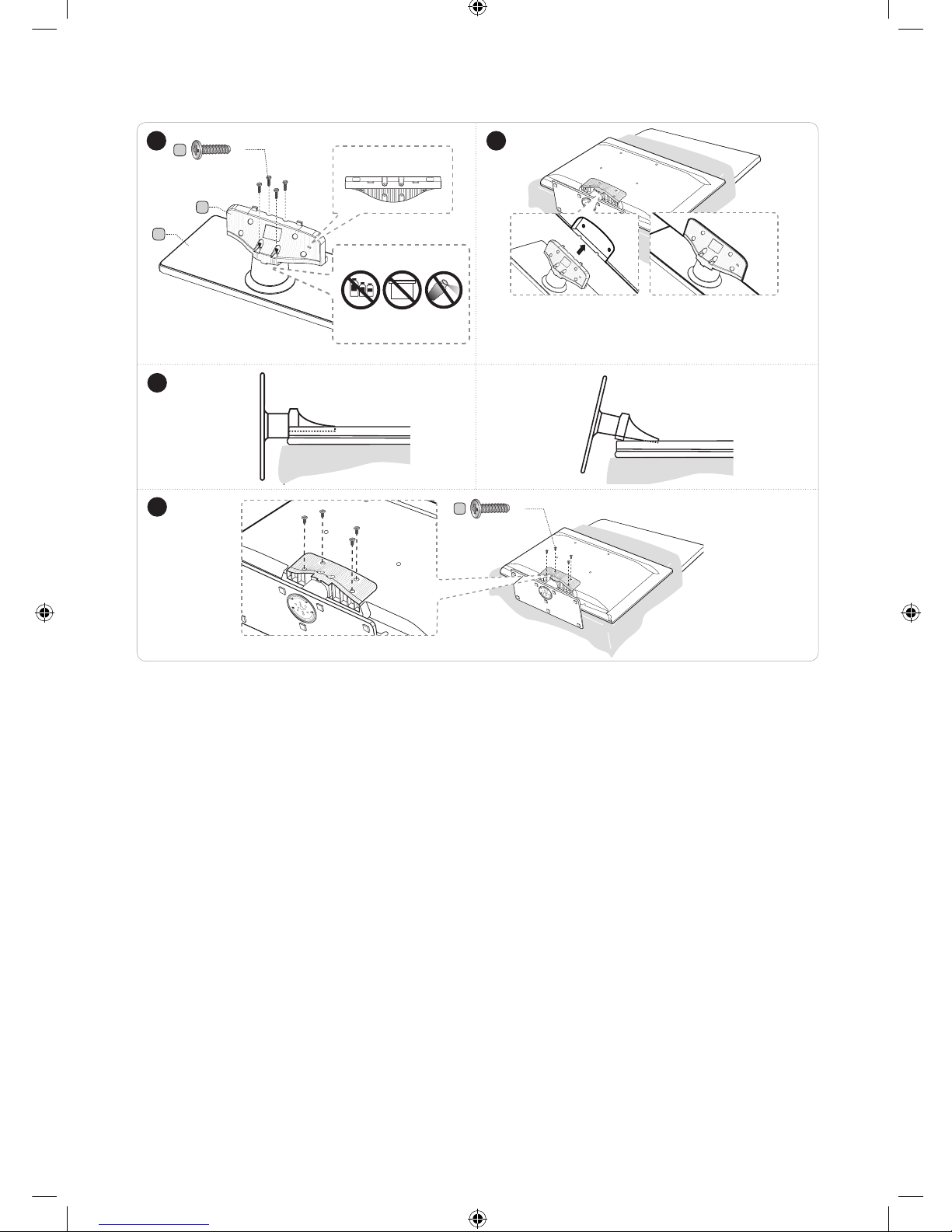
English
4
✎
Place a sof t cloth over the table to protect the TV, and then
place the TV on the cloth screen side down.
✎
Inser t the Stand Guide into the slot of TV bottom side.
1 2
B
A
C
(M4 X L12)
x4
Top View
DO NOT USE
CHEMICALS
DO NOT USE
GREASE
DO NOT USE
OIL
ATTENTION
Rear
Front
C
(M4 X L12)
x4
✎ Make sure to distinguish between the front and back of the Stand and Stand Guide when assembling them.
✎ Make sure that at least two people lift and move the TV.
(Correct assembly)
Side View
3
(Incorrect assembly)
[Hotel-XC]Install Guide.indb 5 2012-11-01 �� 2:24:03
6
English
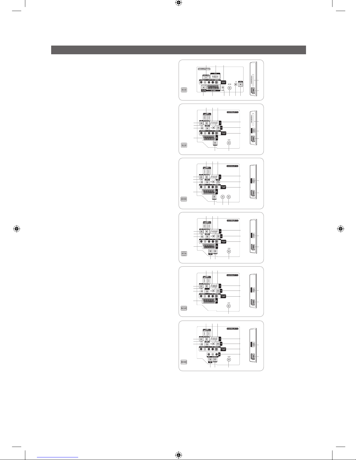
Viewing the Connection Panel
HG22EA470UW
HG22EA473KW
7
460
3 @ #!58
$
Power Input
HG26EA470PW
HG32EA470PW
HG26EA473KW
HG26EA475RW
HG32EA475RW
HG37EA570LW
HG40EA570LW
HDMI IN3
7
7
4
14
6
#
0
5
460
23
3 @ #!58
$
8
!
9
$
@
Power Input
HG26EA476RS
HG32EA476RS
HDMI IN3
$17,1
6$7(//,7(
$17,1
6
#
0
233
7
4
5
8
!
9
14 @
Power Input
HG26AA475RW
HG32AA475RW
HG40AA570LW
(The models of supporting SCART)
HDMI IN3
7
7
4
14
6
#
0
5
460
23
3 @ #!58
$
8
!
9
$
@
HDMI IN3
7
4
14
6
#
0
5
3
8
!
9
@
2%
Power Input
HG26AA473PW
HG32AA473PW
HDMI IN3
7
7
4
14
4
6
#
0
0
#
6
5
460
23
3
3 @ #!58
$
HDMI IN3
4
7
8
!
!
8
9
9
$
@
@
HDMI IN3
7
4
14
6
#
0
5
3
8
!
9
@
5
2%
PILLOW
OUT
^
Power Input
HG26AA470PW
HG32AA470PW
HG32AA570LW
HG40AA570LW
(The models of not supporting SCART)
HDMI IN3
7
7
4
14
4
14
6
#
0
0
0
&
#
#
6
6
5
460
23
3
3
3 @ #!58
$
HDMI IN3
4
7
HDMI IN3
4
7
8
!
!
8
9
9
9
8
$
@
@
@
HDMI IN3
7
4
14
6
#
0
5
3
8
!
9
@
5
5
2%
2%
PILLOW
OUT
^
Power Input
✎
Whenever you connect an external device to your TV, make sure that power on the unit is turned off.
✎
When connecting an external device, match the color of the connection terminal to the cable.
[Hotel-XC]Install Guide.indb 6 2012-11-01 �� 2:24:05
7
English
1 VARIABLE AUDIO OUT: Used for the audio output to the Bathroom speaker. Connect the Bathroom Wall Box and the
Variable port (RCA). (Not available for 22 inch model.)
2 VOL-CTRL: Used to control the volume of the Bathroom speaker. Connect the Bathroom Wall Box and the VOL-CTRL
port.
3 ANT IN: To view television channels correctly, a signal must be received by the set from one of the following sources. An
outdoor antenna / A cable television network / A satellite network.
✎
For Norway & For Sweden: Equipment which is connected to protective earth through a network plug and/or
through other equipment connected to earth, and connected to a cable network, may cause risk of fire. To prevent
this from happening, a galvanic isolator is also installed between the equipment and the cable network when
connecting the equipment to the cable network.
4 HDMI IN 1(DVI), 2, 3: Connects to the HDMI jack of a device with an HDMI output. ( 22" model : HDMI IN port)
✎
No sound connection is needed for an HDMI to HDMI connection.
✎
Use the HDMI IN 1(DVI) jack for DVI connection to an external device. Use a DVI to HDMI cable or DVI-HDMI
adapter (DVI to HDMI) for video connection and the PC/DVI AUDIO IN jacks for audio.
5 PC/DVI AUDIO IN: Connect to the audio output jack on your PC.
6 PC IN: Connect to the video output jack on your PC.
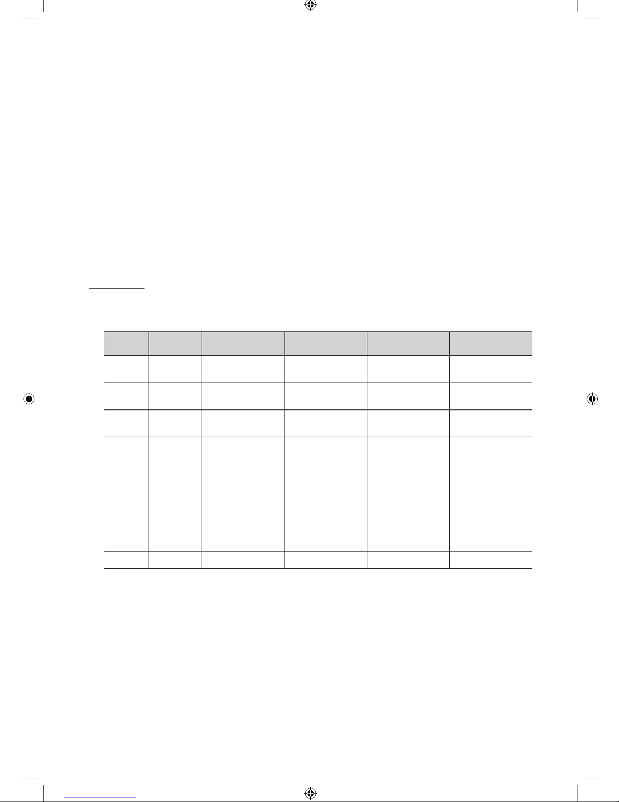
Display Modes
Both screen position and size will vary depending on the type of PC monitor and its resolution.
The resolutions in the table are recommended.
✎
Optimal resolution is 1360 X 768 @ 60 Hz. (Only for 26" / 32" models)
Mode Resolution
Horizontal Frequency
(KHz)
Vertical Frequency
(Hz)
Pixel Clock Frequency
(MHz)
Sync Polarity
(H / V)
IBM
640 x 350
720 x 400
31,469
31,469
70,086
70,087
25,175
28,322
+/-
-/+
MAC
640 x 480
832 x 624
35,000
49,726
66,667
74,551
30,240
57,284
-/-
-/-
VESA CVT
720 x 576
1280 x 720
35,910
56,456
59,950
74,777
32,750
95,750
-/+
-/+
VESA DMT
640 x 480
640 x 480
640 x 480
800 x 600
800 x 600
800 x 600
1024 x 768
1024 x 768
1024 x 768
1280 x 720
1360 x 768
31,469
37,500
37,861
37,879
46,875
48,077
48,363
56,476
60,023
45,000
47,712
59,940
75,000
72,809
60,317
75,000
72,188
60,004
70,069
75,029
60,000
60,015
25,175
31,500
31,500
40,000
49,500
50,000
65,000
75,000
78,750
74,250
85,500
-/-
-/-
-/+/+
+/+
+/+
-/-
-/+/+
+/+
+/+
VESA GTF 1280 x 720 52,500 70,000 89,040 -/+
[Hotel-XC]Install Guide.indb 7 2012-11-01 �� 2:24:06
8
English
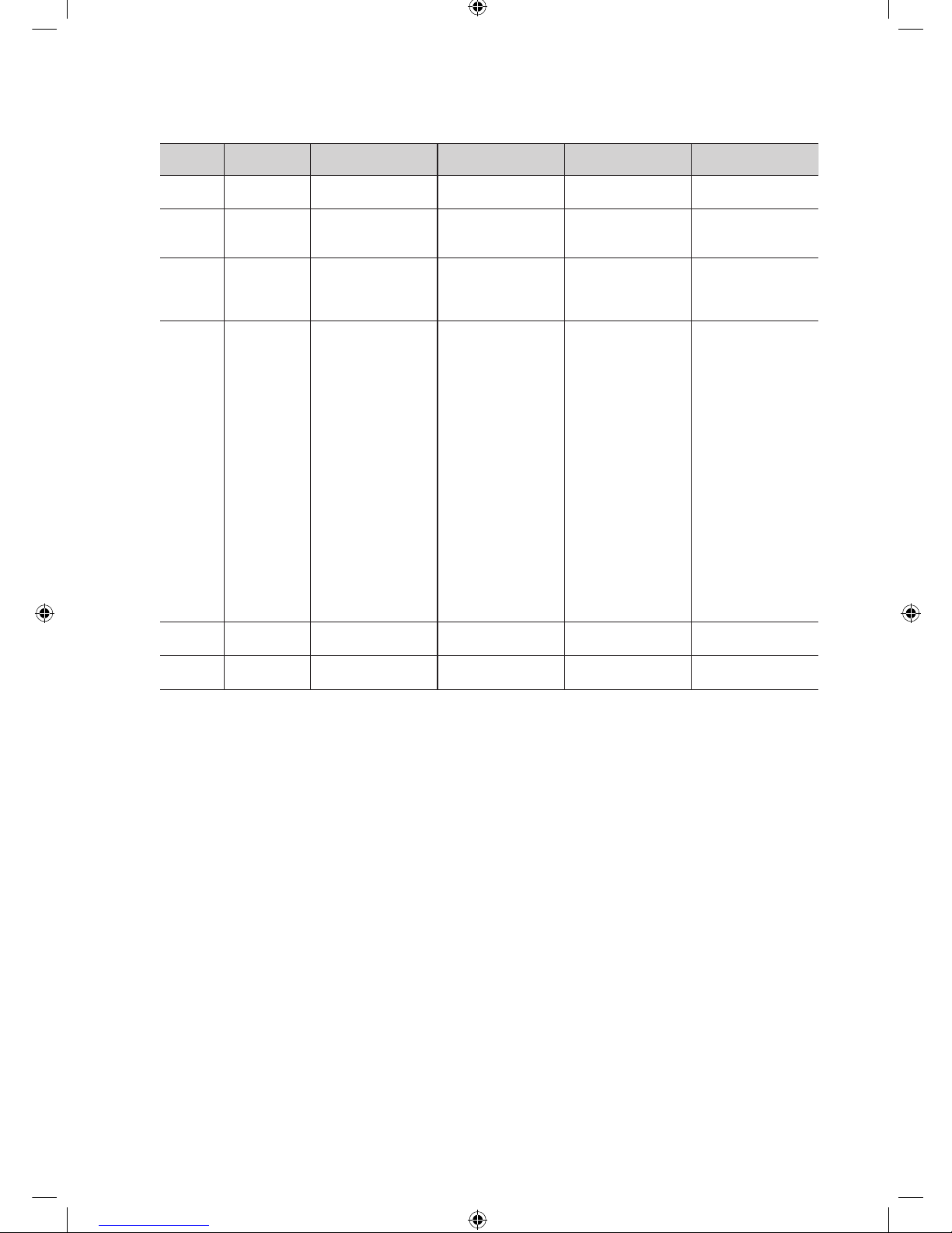
✎
Optimal resolution is 1920 X 1080 @ 60 Hz. (Only for 22" / 37" /40” models)
Mode Resolution
Horizontal Frequency
(KHz)
Vertical Frequency
(Hz)
Pixel Clock Frequency
(MHz)
Sync Polarity
(H / V)
IBM
640 x 350
720 x 400
31,469
31,469
70,086
70,087
25,175
28,322
+/-
-/+
MAC
640 x 480
832 x 624
1152 x 870
35,000
49,726
68,681
66,667
74,551
75,062
30,240
57,284
100,000
-/-
-/-
-/-
VESA CVT
720 x 576
1152 x 864
1280 x 720
1280 x 960
35,910
53,783
56,456
75,231
59,950
59,959
74,777
74,857
32,750
81,750
95,750
130,000
-/+
-/+
-/+
-/+
VESA DMT
640 x 480
640 x 480
640 x 480
800 x 600
800 x 600
800 x 600
1024 x 768
1024 x 768
1024 x 768
1152 x 864
1280 x 1024
1280 x 1024
1280 x 720
1280 x 800
1280 x 800
1280 x 960
1360 x 768
1440 x 900
1440 x 900
1680 x 1050
31,469
37,861
37,500
37,879
48,077
46,875
48,363
56,476
60,023
67,500
63,981
79,976
45,000
49,702
62,795
60,000
47,712
55,935
70,635
65,290
59,940
72,809
75,000
60,317
72,188
75,000
60,004
70,069
75,029
75,000
60,020
75,025
60,000
59,810
74,934
60,000
60,015
59,887
74,984
59,954
25,175
31,500
31,500
40,000
50,000
49,500
65,000
75,000
78,750
108,000
108,000
135,000
74,250
83,500
106,500
108,000
85,500
106,500
136,750
146,250
-/-
-/-
-/+/+
+/+
+/+
-/-
-/+/+
+/+
+/+
+/+
+/+
-/+
-/+
+/+
+/+
-/+
-/+
-/+
VESA GTF
1280 x 720
1280 x 1024
52,500
74,620
70,000
70,000
89,040
128,943
-/+
-/-
VESA DMT /
DTV CEA
1920 x 1080p 67,500 60,000 148,500 +/+
✎
When using an HDMI/DVI cable connection, you must use the HDMI IN 1 (DVI) jack.
✎
The interlace mode is not supported.
✎
The set might operate abnormally if a non-standard video format is selected.
✎
Separate and Composite modes are supported. SOG is not supported.
7 USB / CLONING
– Connector for software upgrades and Contents Home, etc.
– Service connection.
8 DATA
– Used to support data communication between the TV and the SBB.
– The TV jack type is RJ-12.
9 RJP: This port is an RJP (Remote Jack Pack) communication port that enables connecting different devices to additional
module so as to improve device use convenience.
[Hotel-XC]Install Guide.indb 8 2012-11-01 �� 2:24:07

9
English
0 COMPONENT IN / AV IN
– Connects Component video / audio.
– Connect component video cables (optional) to the component jacks ("PR", "PB", "Y") on the rear of your TV and the
other ends to corresponding component video out jacks on the DVD.
– If you wish to connect both the Set-Top Box and DVD, you should connect the Set-Top Box to the DVD and connect
the DVD to the component jacks ("PR", "PB", "Y") on your TV.
– The PR, PB and Y jacks on your component devices (DVD) are sometimes labeled Y, B-Y and R-Y or Y, Cb and Cr.
– Connect RCA audio cables (optional) to [R - AUDIO - L] on the rear of the TV set and the other ends to corresponding
audio out jacks on the DVD.
! EXT (RGB)
Connector
Input Output
Video Audio (L/R) RGB Video + Audio (L/R)
EXT 0 0 0 Only TV or DTV output is available
✎
Inputs or outputs for external devices, such as VCR, DVD, video game device or video disc players.
@ HEADPHONE JACK
– Headphones may be connected to the headphone jack on your TV. While the headphones are connected, the sound
from the built-in speakers will be disabled.
# HP-ID
$ COMMON INTERFACE
% AUDIO OUT
^ PILLOW OUT: connect the pillow speaker
& AV IN1
[Hotel-XC]Install Guide.indb 9 2012-11-01 �� 2:24:07
10
English
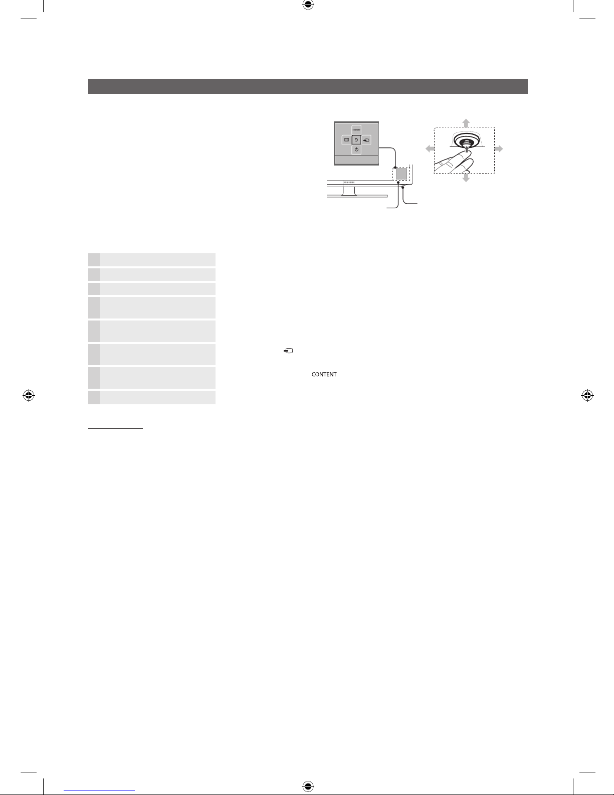
Using the TV’s Controller (Panel Key)
TV Controller is a multi directional button that helps navigate without
remote control.
✎
Some functions which require a PIN code may not be
available.
✎
The product colour and shape may vary depending on the
model.
✎
Exits the menu when pressing the controller more than 1
second.
✎
When selecting the function by moving the controller to
the up/down/left/right directions, be sure not to press the
controller. If you press it first, you cannot operate it to move
the up/down/left/right directions.
Remote control sensor
TV Controller
Function menu
Return
Down (Front)
Up (Rear)
Right
Left
Power on Turns the TV on by pressing the controller in standby mode.
Adjusting the volume Adjusts the volume by moving the controller from side to side when the power is on.
Selecting a channel Selects a channel by moving the controller up and down when the power is on.
Using the function menu Press the controller when the power is on, then the function menu screen appears. If you press it
again, the function menu screen disappears.
Using the Menu
Selects the MENU(m) by moving the controller in the function menu screen. The OSD(On Screen
Display) of your TV’s feature appears.
Selecting the Source Selects the Source( ) by moving the controller in the function menu screen. The Source list
screen appears.
Selecting the Contents Home Selects the Contents Home( ) by moving the controller in the function menu screen. The
Contents Home main screen appears.
Power Off
Selects the Power Off(P) to turn the TV off by moving the controller in the function menu screen.
Standby mode
Do not leave your TV in standby mode for long periods of time (when you are away on a holiday, for example). A small amount of electric power
is still consumed even when the power button is turned off. It is best to unplug the power cord.
[Hotel-XC]Install Guide.indb 10 2012-11-01 �� 2:24:08
11
English
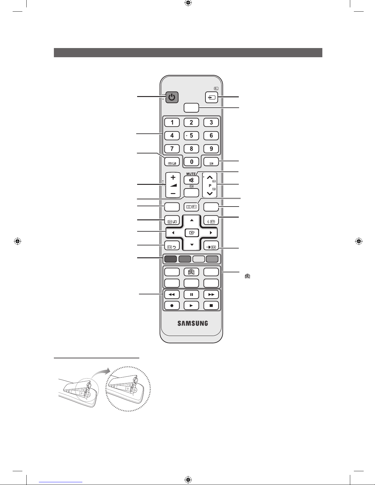
Viewing the Remote Control
✎ This is a special remote control for the visually impaired persons and has Braille points on the Power, Channel and
Volume buttons.
Installing batteries (Battery size: AAA)
✎
NOTE
x
Use the remote control within 23 feet from the TV.
x
Bright light may affect the performance of the remote
control. Avoid using nearby special fluorescent light or neon
signs.
x
The colour and shape may vary depending on the model.
x
Remocon button 'HOME' & '3D' is not supported. When
press those button, TV unit do not give ANY respond.
GUIDE
CLOCK
CH LIST
POWER
HOME
@
TV
CONTENT
ALARM
P. SIZE
SUBT.
ABCD
DUAL
I-II
HDMI
PRE-CH
TTX/MIX
SOURCE
MENU
INFO
TOOLS
RETURN
EXIT
Turns the TV on and off.
Display and select the available video
sources.
Return to the previous channel.
Change channels.
Electronic Programme Guide (EPG) display.
Press to display information on the TV
screen.
CLOCK: When you press INFO key in
standby mode, TV screen will display the
time.
Exit the menu.
HOME : Switch to the HOME screen.
: Turns the 3D image on or off. ( Only for
LED 6 SERIES )
DUAL f-g: Sound effect selection.
ALARM: Enter the hour you want the TV
to turn on.
P.SIZE: Choose the picture size.
SUBT.: Displays digital subtitles.
Display the main on-screen menu.
Cut off the sound temporarily.
Have direct access to channels.
Adjust the volume.
Display channel list on the screen.
View the Contents Home.
Quickly select frequently used functions.
Return to the previous menu.
Buttons in the Channel list, Contents
Home menu, etc.
Enter the hour your want the TV to turn on.
Use these buttons in the Contents Home.
Select on-screen menu items and change
menu values.
Alternately selects Teletext, Double or Mix.
Selects the HDMI mode directly.
[Hotel-XC]Install Guide.indb 11 2012-11-01 �� 2:24:09
12
English
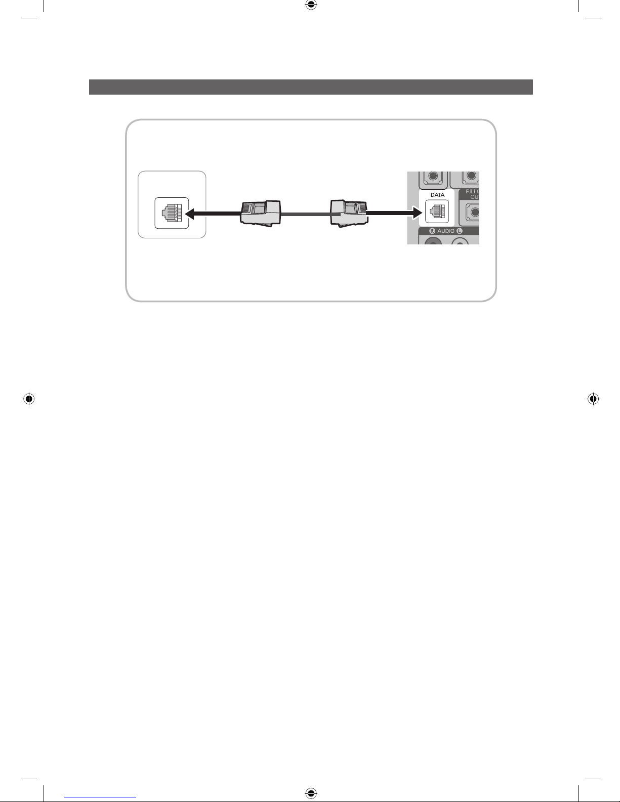
Connecting the TV with SBB
ETH MODEM
PILLOW
OUT
Data Cable
TV Rear Panel
Hotel Server
STB(Set Top Box) or
SBB(Set Back Box)
1. Connect the DATA jack of the TV to the [ETH MODEM] jack of the STB(SBB) with the Data cable.
✎
Use data communication.
[Hotel-XC]Install Guide.indb 12 2012-11-01 �� 2:24:10
13
English
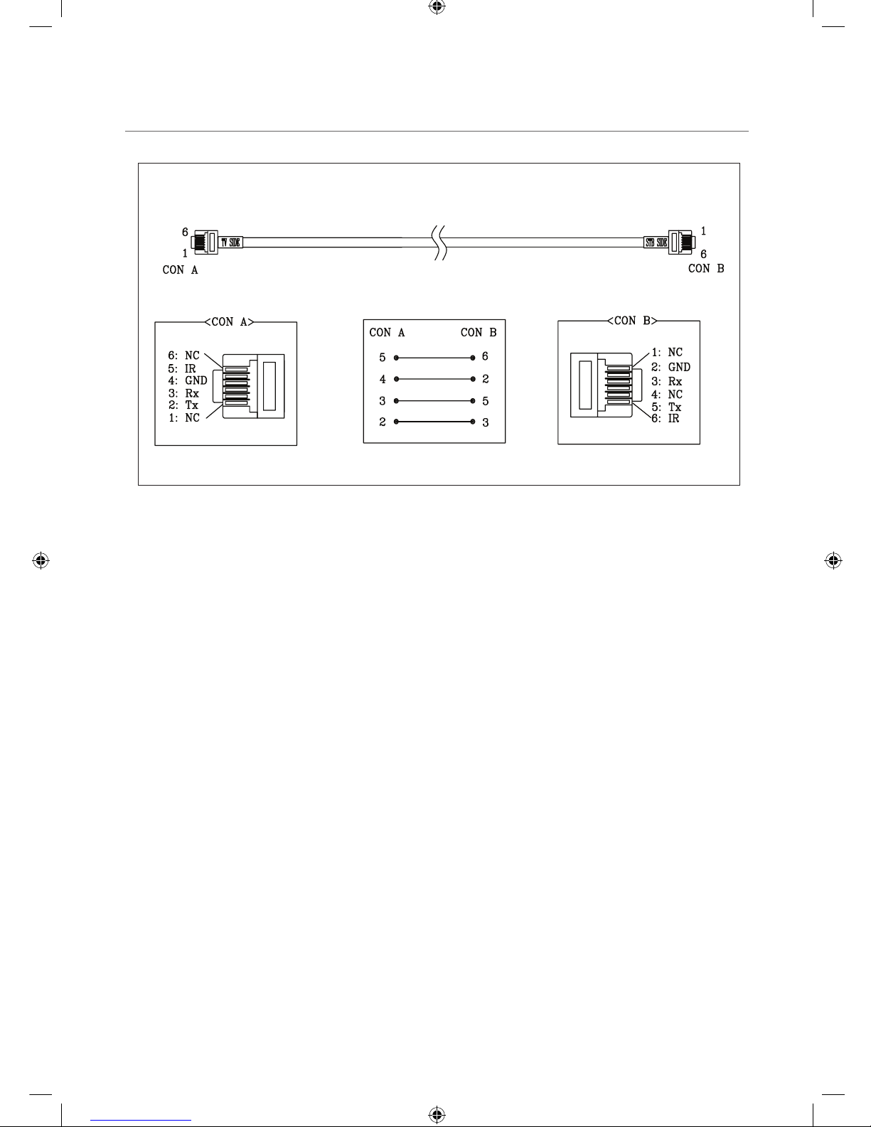
¦ List of Vendors and Compatible Data Cables Supplied with the TV
y Confirm you are using the correct data cable for your vendor. Refer to the code label on the data cables.
[Hotel-XC]Install Guide.indb 13 2012-11-01 �� 2:24:10
14
English
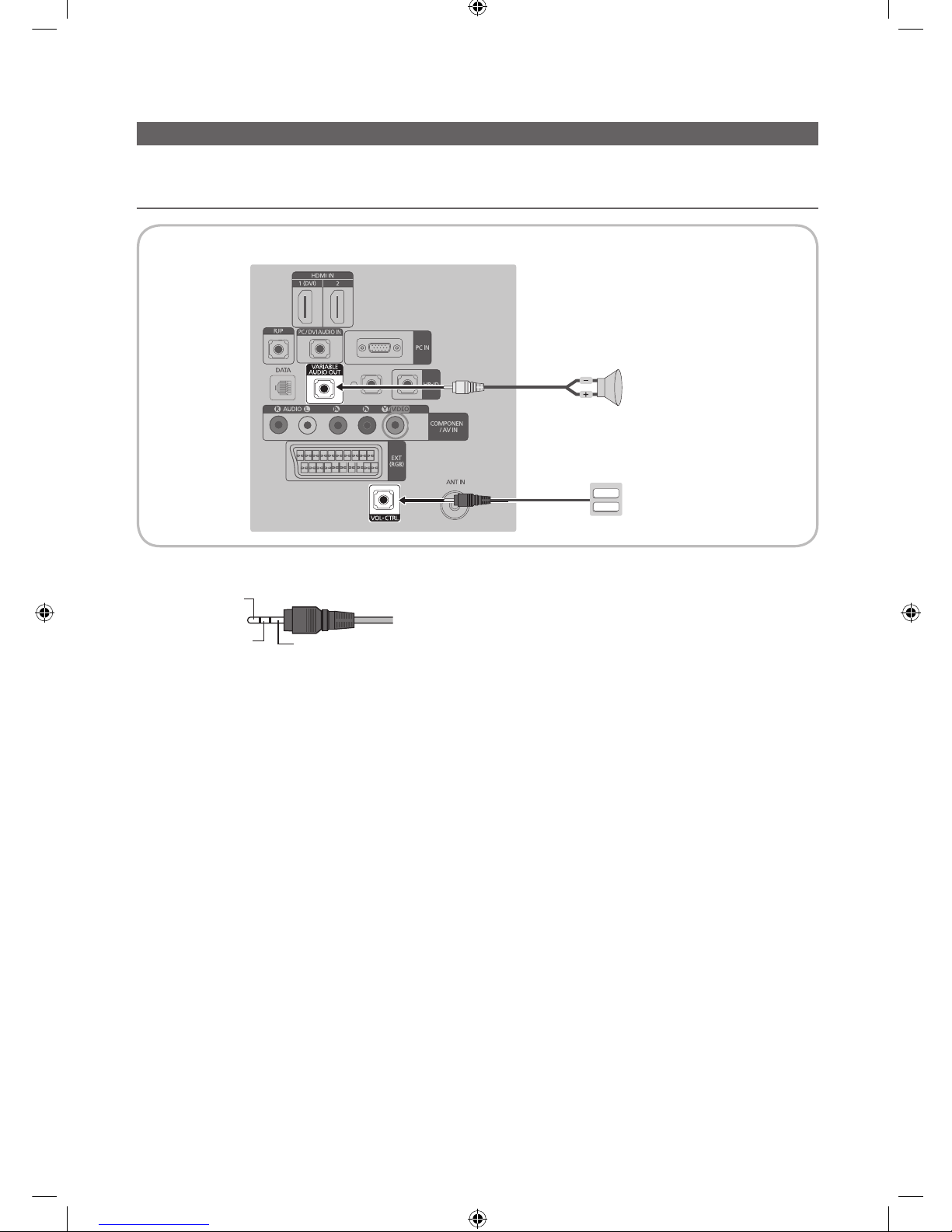
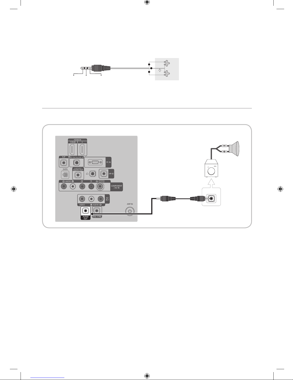
Connecting the Bathroom Speakers
You can connect the Bathroom Speakers in the following method.
¦ Connecting through the Variable Output (available without an external amplifier)
1. Connect the VARIABLE AUDIO OUT port of the TV to the Bathroom Wall Speakers of the hotel.
Speaker +
Speaker -
N/C
2. Connect the VOL-CTRL jack of the TV to the Volume Control Box Switch port on the Bathroom Wall of the hotel.
✎
The maximum speaker output is 4W, 8Ω.
y Installing the Volume Control
– If you configure the Volume Control Box as shown in the figure, you can control the volume of the bathroom speakers.
– The jack that is connected from the Volume Control Box to the TV is a 3.5mm normal Phone jack.
– Volume Control Box switch consists of Tact switch.
✎
Setting the Sub AMP Mode
– 0: Turns the Sub AMP function off (PWM off).
– 1: Determines the Sub volume according to the main volume control. That is, the sub volume is determined according
to the Power On Volume, the Min Volume, and the Max Volume values of the Hotel Mode.
– 2: Determines the volume according to the bathroom control panel setting.
VOL+
VOL
-
TV Rear Panel
Volume Control Box
Speaker
2
1
[Hotel-XC]Install Guide.indb 14 2012-11-01 �� 2:24:11
15
English
y Variable Output Port Specifications
– Speaker Wire: Use speaker cable no more than 82 feet (25m) in length.
Volume Control Box
VOL - DOWN
( White 1 )
VOL - UP
( Black /Red 2 )
GND
( Shield Wire 3 )
VOL +
VOL
-
1
2
3
¦ Connect through the Fixed Output (available without an external amplifier)
✎
This function is only supported in HG26AA470PW, HG32AA470PW, HG32AA570LW, HG40AA570LW (without SCART).
(The other models are not available)
1. Connect the AUDIO OUT port of the TV and the Audio In port of the audio amplifier with a stereo cable.
AUDIO IN
TV Rear Panel
Audio Amplifier
1 Stereo cable
[Hotel-XC]Install Guide.indb 15 2012-11-01 �� 2:24:13
16
English
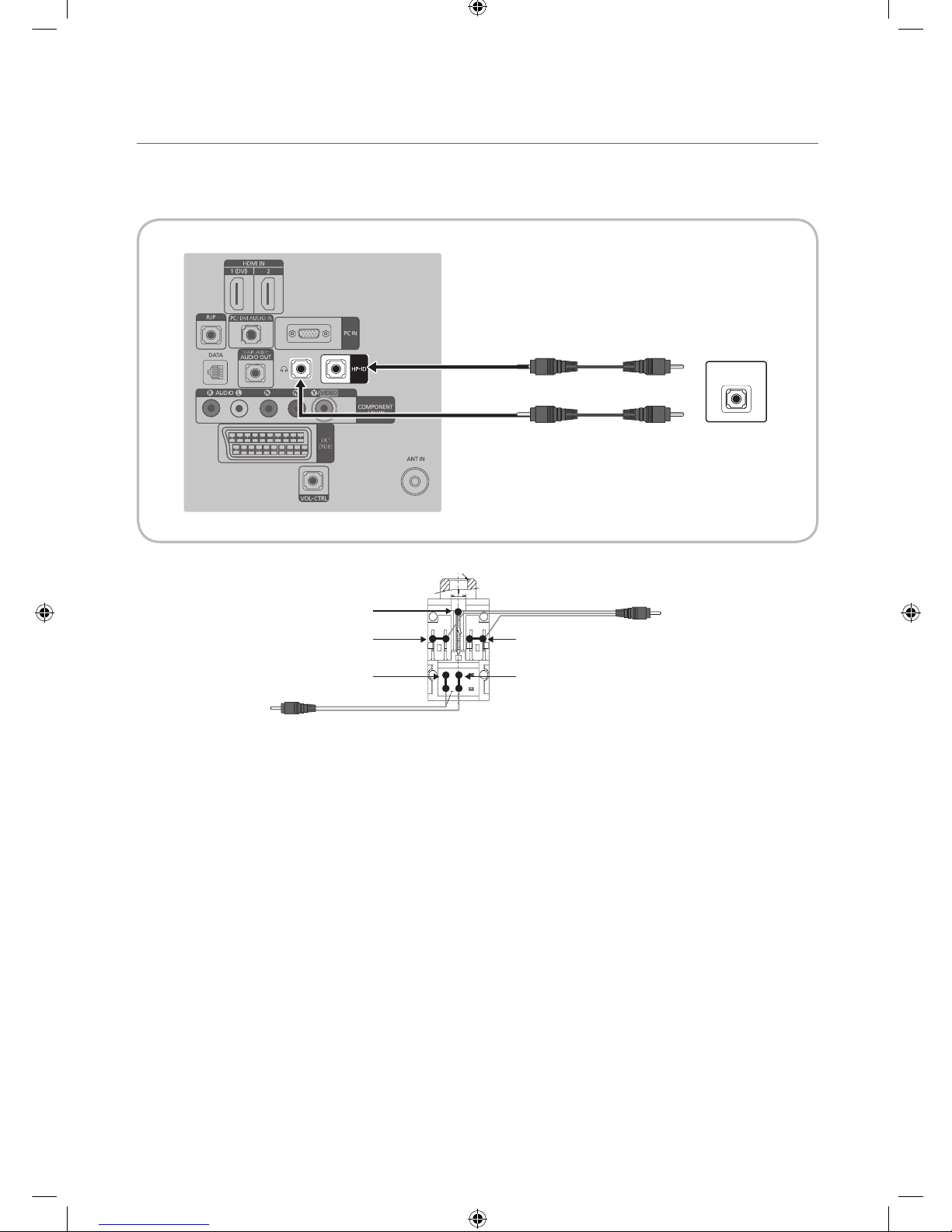
¦ Audio Loop In
An additionally created Headphone Box can be installed on a bed or business desk so that users can use it conveniently. The
installation procedures are given below.
y Detailed Drawing of the Headphone Box.
HEADPHON BOX
TV Headphones jack
Whitewire (Audio-L)
Shield Wire
TV HP-ID jack
Red wire + White wire
Red Wire (Audio-R)
Shield wire
TV Rear Panel
Headphone Box
[Hotel-XC]Install Guide.indb 16 2012-11-01 �� 2:24:13
17
English
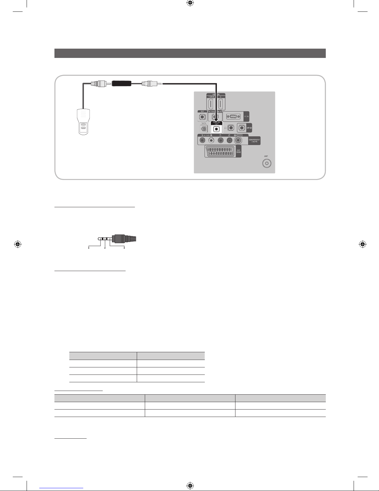
Connecting a Pillow Speaker
You can connect a pillow speaker to the TV in the hospital using a jumper cable. The speaker functions as a remote control
and speaker.
1. Connect the pillow speaker jumper cable (cable sold separately) from the television's PILLOW OUT Port to the pillow
speaker jack on the wall behind the television.
Pillow Speaker Jack Specifications
y Output jack: RCA type
y Input jumper pin: 1/8" 3-conductor stereo phone pin.
y Signal specifications: Tip-Audio, Ring-Data/Channel change, Sleeve-Common
Tip
Ring Sleeve
VOL +
VOL
-
1
2
3
How to Use the Pillow Speaker
y Analog type speaker: The pillow speaker has one key.
– Power On: press the key when the TV is in standby mode.
– Channel Up: press the key when the speaker is on.
– Power Off: press and hold the key for more than 3 seconds when the speaker is on.
– An Analog type speaker always works regardless of the Pillow Speaker Type value set in the Hospital mode
setup menu.
y Digital type speaker: The TV supports the Samsung, Philips, or Zenith code.
– This speaker is only compatible with a specified IR code. You can change the code in the Hospital mode setup
menu.
– The TV gives priority to the Samsung remote control over the pillow speaker's wired remote control.
– Option : Channel Menu Display.
Pillow Speaker Type Pillow Speaker IR Code
CZ Zenith
CP Pilips
CS Samsung
Pillow Sound Control
Speaker Selection Menu TV Speaker Pillow Speaker
Main Sound Sound
External No Sound Sound
y Anynet+ function is not supported in hospital models.
Pillow Volume
y Pillow Volume change the setting about gain value of Audio amplifier to Low, Normal and High.
PILLOW
OUT
TV Rear Panel
Jumper Cable
Pillow Speaker
[Hotel-XC]Install Guide.indb 17 2012-11-01 �� 2:24:14
18
English
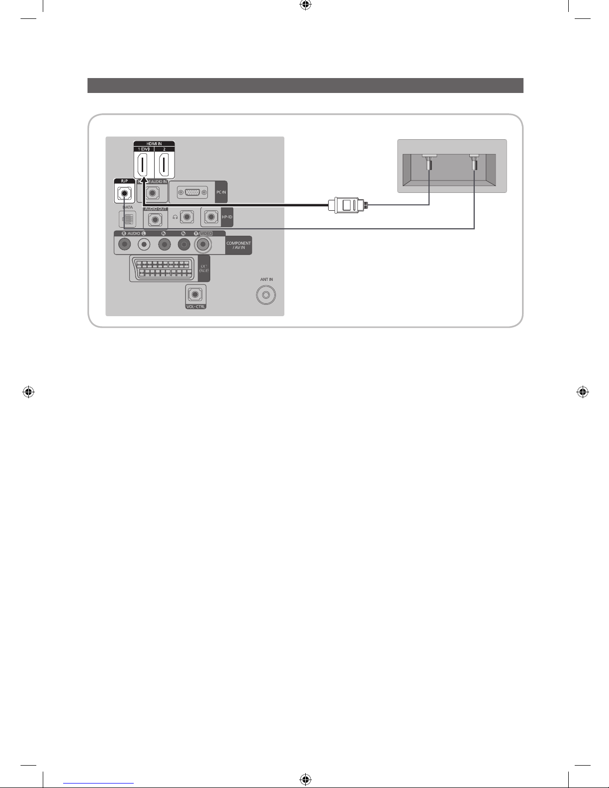
Connecting the MediaHub HD
Output of any external source connected to MediaHub HD on hotel desk.
1. Connect the RJP port of the TV and the RS/232 port of the MediaHub HD.
2. Connect the HDMI IN (1(DVI) or 2) port of the TV and the HDMI port of the MediaHub HD. ( 22" model : HDMI IN port )
y MediaHub HD
– The MediaHub HD is a hardware module that has different Audio Video inputs (A/V, Audio, PC, HDMI and USB) and
corresponding outputs. The corresponding output sources are connected from MediaHub to TV. The MediaHub
communicates with the TV via RS232. Hot Plug & Play is a function that allows hotel guests to connect an external
source to the MediaHub. The MediaHub communicates with the TV by sending messages regarding Active/Inactive
sources. The TV will switch to the Active external source.
– You have to connect the HDMI of the MediaHub to the HDMI IN 1(DVI) port of the TV.
– When the TV is on, connect the TV and the RJP within 10 seconds.
y Special features
– PIP
– Auto Detection
HDMI
USB RS/232
TV Rear Panel MediaHub HD Rear
2
HDMI cable
1
RS-232 Data Cable
[Hotel-XC]Install Guide.indb 18 2012-11-01 �� 2:24:15
19
English
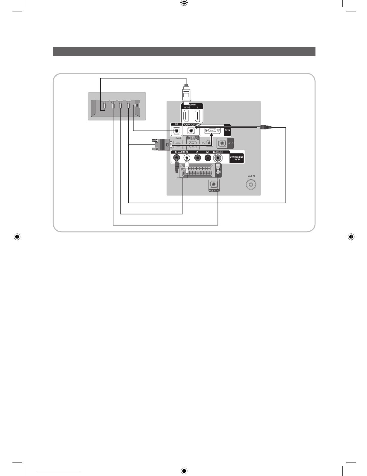
Connecting the RJP (Remote Jack Pack)
Output of any external source connected to RJP on hotel desk.
1. Connect the PC IN / PC/DVI AUDIO IN port of the TV to the PC/AUDIO port of the RJP.
2. Connect the AV IN [VIDEO]/[L-AUDIO-R] port of the TV to the VIDEO port of the RJP.
3. Connect the AV IN [VIDEO] port of the TV to the VIDEO port of the RJP.
4. Connect the HDMI IN (1(DVI), 2 or 3) port of the TV and the HDMI port of the RJP. ( 22" model : HDMI IN port )
5. Connect the RJP port of the TV and the RS/232 port of the RJP.
✎
The RJP (Remote Jack Pack) compatible with this Samsung TV is TeleAdapt TA-7610, TA-7650 (HD) and TA-7660
(HD Plus).
y RJP (Remote Jack Pack): RJP stands for Remote Jack Pack. The RJP is a hardware module that has different Audio
Video inputs (A/V, Audio, PC and HDMI) and corresponding outputs. The corresponding output sources are connected
from RJP to TV. The RJP communicates with the TV via RS232. Hot Plug & Play is a function that allows hotel guests
to connect an external source to the RJP. The RJP communicates with the TV by sending messages regarding Active/
Inactive sources. The TV will switch to the Active external source according to the priority set by the User.
✎
You can select HDMI IN (1(DVI), 2 or 3) and AV IN for connecting RJP. ( 22" model : HDMI IN port )
USB HDMI VIDEO
AUDIO AUDIO/PC
RS/232
TV Rear Panel
RJP Rear
5
1
D-sub / PC Audio cable
2 Audio Cable
3 Video Cable
4 HDMI cable
[Hotel-XC]Install Guide.indb 19 2012-11-01 �� 2:24:16

20
English
✎
When the T V is on, connect the TV and the RJP within 10 seconds.
y The RJP can be returned to the factory default settings by pressing the A/V and HDMI buttons simultaneously for 10
seconds. All LEDs blink 5 times to Acknowledge that the rest has been performed.
y The RJP will automatically turn off any LEDs after 5 minutes to avoid unnecessary light pollution in the hotel room. The
LEDs that were turned off will turn on again if the guest touches any of the buttons and the 5 minute timer will restart. If the
guest then touches another source button, the TV will change to the selected source and the corresponding LED will be lit.
y After an RJP Reset or a TV Power OFF/ON, it takes approx. 10 seconds to establish communications between the TV and
the RJP.
y The following table shows the approximate time in seconds to switch from the TV to the input source, based on the
priority.
✎
Scenario 1: When no inputs are connected.
Source To Connect
AV 2 Sec
PC 0.7 Sec
HDMI 3.9 Sec
✎
Scenario 2: When two or more inputs are connected and an Input source is disconnected and then reconnected.
Source Disconnect To Connect Total
AV 4.5 Sec 2 Sec 6.5 Sec
PC 0.7 Sec 0.7 Sec 1.4 Sec
HDMI 3.9 Sec 3.9 Sec 7.8 Sec
✎
E.g. If the RJP has all its live sources AV, PC and HDMI connected, AV is viewed as the highest priority. If the RJP is
in HDMI mode, and a guest removes and reconnects the AV, the minimum time required to switch to the AV is 6.5
seconds.
y To connect audio (Ipod or Mp3), Music mode should be ON and Jack Ident detect should be OFF.
y A/V, PC and HDMI input sources are supported.
[Hotel-XC]Install Guide.indb 20 2012-11-01 �� 2:24:16
21
English
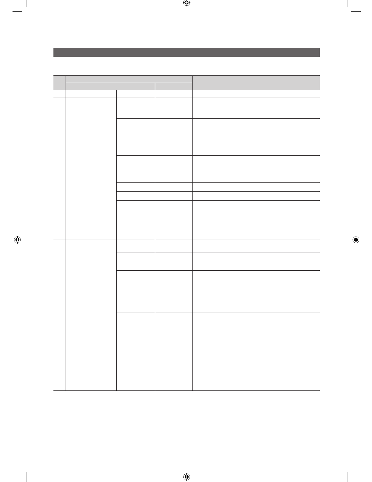
Setting the Hotel Option Data
To Enter: Press the MUTE → 1 → 1 → 9 → ENTERE buttons in order. (From the Hospitality mode, the Standalone mode is set.)
To Exit from this menu : power off and turn on again.
No
Hotel TV Function
Description
Category initial value
1 Hospitality Mode - Standalone
Select the Hotel TV mode. (Standalone / Interactive)
2 SI Vendor - OFF
Select the SI Vendor
3 Power On
Power On
Channel EN
User Defined
TV will turn on to particular Channel.
Power On
Channel
1
TV will turn on to this particular Channel.
Channel Type ATV
Provides channel Type description for Power On channel
selected. i.e.
Selected channel analog or Digital & antannae selection(Air or
Cable).
Power On
Volume EN
User Defined
TV will turn on with this Volume Level.
Power On
Volume
10
TV will turn on with this Volume Level.
Min Volume 0
Minimum Volume Level setting user can set
Max Volume 100
Maximum Volume Level setting user can set
Power on
source
TV
Select the Input source when TV is turned on initially.
Power On
Option
Last Option
Power On(AC Power On) Option
- STN-BY : Stand-By Mode
- Power On : Power On
- LAST OPT : Last Power State
4 Channel
Channel Setup -
User can set channel option.
Such as Auto Tunning, Manual Tunning, Antenna setting.
Channel Editor -
Provided option for editing Channel Name and Number and
video.
Mute settings for channels in channel List.
Mixed Channel
Map
OFF
Mix Analogue and Digital Channels
Dynamic SI OFF
On : No Check of the DTV Program channel number.(DTV
channel editor accessible, but addtional channel Program
number update not supported)
Off : Check the DTV Program channel number. (DTV channel
editor inaccessible)
CH Rescan
MSG
ON
This is a display option for the OSD text that appears when
a user configures the country specifications in hotel models.
This option determines whether to activate the items that
are only executed after a manual user confirmation when
the notification message is displayed while the country
specifications are being configured.
On - When TV has an event for setting change because of
country spec, It will be shown on the screen.
Off - Even TV has an event for setting change, because of
country spec, it will not be shown on the screen.
Pan Euro MHEG OFF
If Pan EURO MHEG is set to On, MHEG is On regardless of
the product specifications or region. (Even if the region does
not support MHEG, it is supported in case the hotel supports
MHEG.)
[Hotel-XC]Install Guide.indb 21 2012-11-01 �� 2:24:17
22
English
No
Hotel TV Function
Description
Category initial value
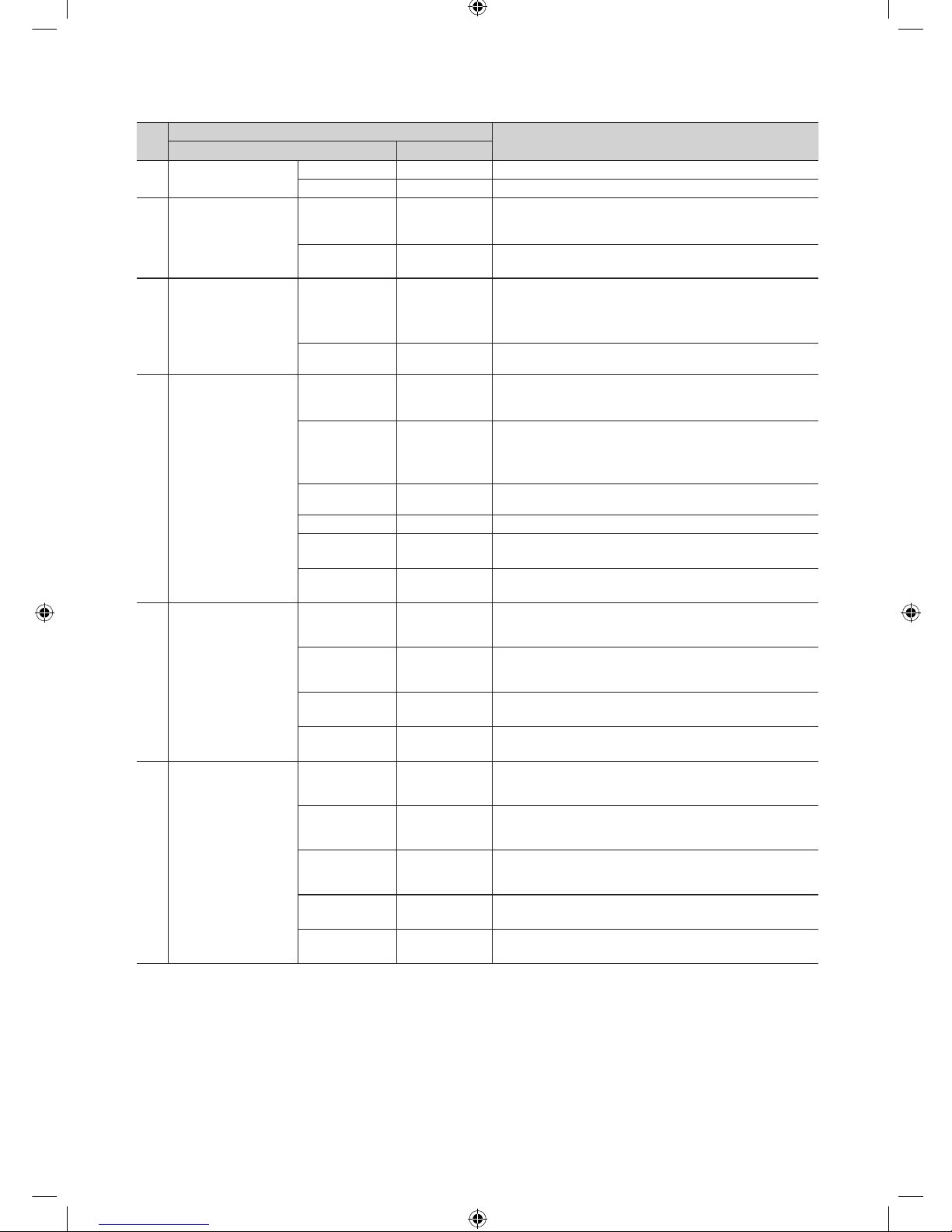
5 My Channel
My channel En OFF
Set the My channel function ON/OFF.
Genre Editor
User can set the genre for searched channel.
6 Menu OSD
Picture Menu
Lock
OFF
Provided option for editing Channel Name and Number and
video.
Mute settings for channels in channel List.
Menu display ON
- On : Main Menu display
- Off : Main Menu No display
7 Operation
Panel Button
Lock
Unlock
Front panel(Local key) operation on/off
- Unlock: Unlock All panel key
- Lock: Lock All panel key
- OnlyPower : Lock All panel key except Power panel key
Subtitle Auto On Off/On
Set the automatically subtitle on function when user set the
nation to France.
8 Clock
SW Clock Off/On
Set the S/W Clock function On/Off.
- TV displays the current time when the user pushs Info Key of
the remote control in Stand-by mode.
Local time Manual
Selection of the way to update clock data
- Manual: Use clock data from DVB channel or manual clock
setting When the TV is in the stand-alone mode.
- TTX: manual clock setting (with updating from TTX data).
Time Format 24 Hour
Select time expression method(12H/24H) Reset AC power
after setting this option.
Clock Test Failure
To test CLOCK itself (brightness and pixel).
Clock Normal
Dimming
4
CLOCK brightness selection.
Clock STD-BY
Dimming
1
CLOCK STY-BY brightness selection.
9 Music Mode
Music Mode AV OFF
To get music output from mp3/audio player in AV Input
Source.
Audio enabled, video disabled in this mode
Music Mode PC OFF
To get music output from mp3/audio player in PC Input
Source.
Audio enabled, video disabled in this mode.
Music Mode
Comp
OFF
To get music output from mp3/audio player in Component
Input Source. Audio enabled, video disabled in this mode
Music Mode
Backlight
OFF
Backlight On/Off option in Music mode to save energy
10 External Device
RJP(7610)
Priority AV
1
If the jack priority is set, the corresponding source is
automatically set when a jack is inserted according to the jack
priority
RJP(7610)
Priority PC
2
If the jack priority is set, the corresponding source is
automatically set when a jack is inserted according to the jack
priority.
RJP(7610)
Priority HDMI
3
If the jack priority is set, the corresponding source is
automatically set when a jack is inserted according to the jack
priority.
RJP(7610) AV
Option
AV1
Select RJP AV Source (AV1).
RJP HDMI
Option
HDMI1
Select RJP HDMI Source (HDMI1/HDMI2/HDMI3).
[Hotel-XC]Install Guide.indb 22 2012-11-01 �� 2:24:17
23
English
No
Hotel TV Function
Description
Category initial value
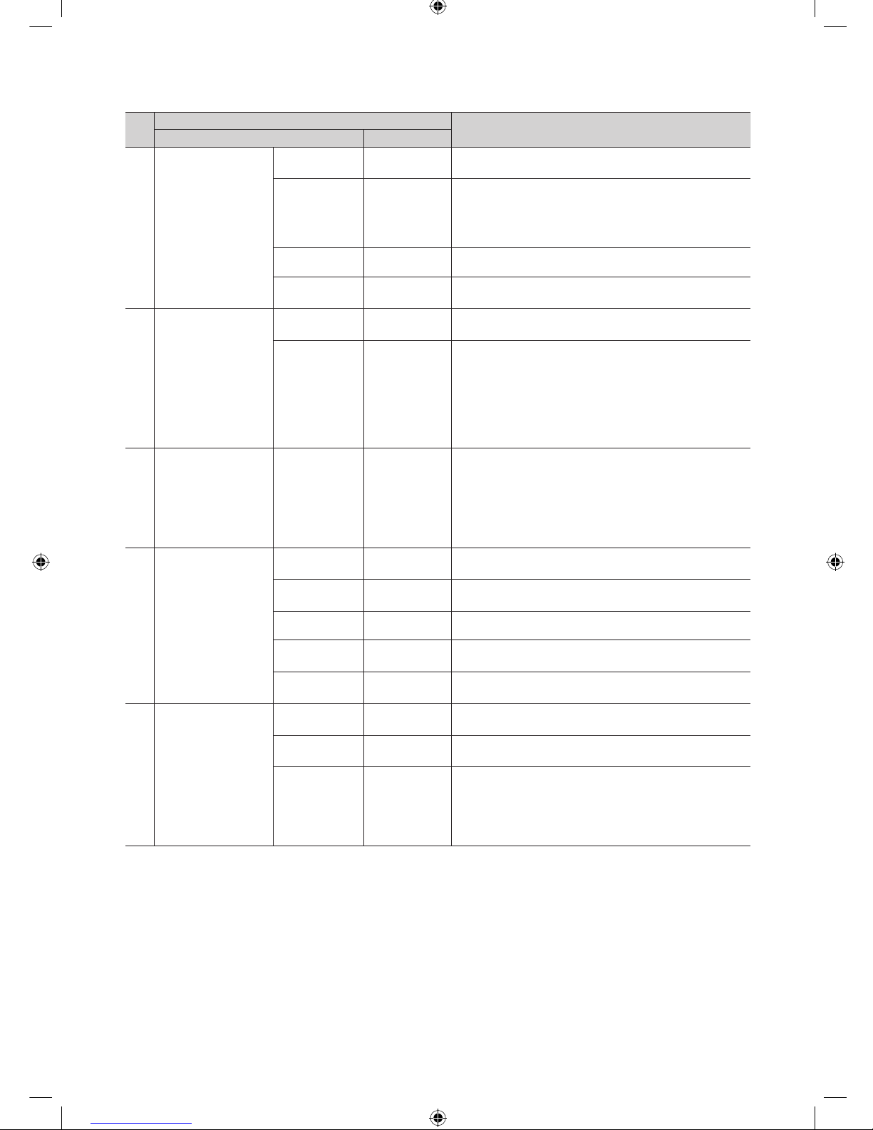
11 External Source
USB Media
Mode
Default
Control Pop-Up menu at USB insert to TV.
External Source
Banner
Enable/Disable
Users can set External Source Banner to On or Off.
On : When TV power On or Mode changed, TV will disply the
external source banner.
Off : When TV power On or Mode changed, TV will not disply
the external source banner.
Auto Source OFF
While TV is in power on state, if PC source is connected to TV,
TV will automatically switch to PC mode.
Anynet+ Return
Source
Power On
Src….
Set the return source after closing Anynet+.
12 Bathroom Speaker
Sub AMP
volume
13
Sub AMP Volume level at power on initial condition.
Sub AMP mode 2
Determines the Sub AMP operation mode.
- 0: Turns the Sub AMP function off (PWM off).
- 1: Determines the Sub volume according to the main volume
control.
That is, the sub volume is determined according to the Power
On Volume, the Min Volume, and the Max
- 2: Determines the volume according to the bathroom control
panel setting.
13 Eco Solution Energy Saving Off
This feature adjusts the brightness of the TV in order to reduce
power consumption.
- Off: Turns off the energy saving function.
- Low: Sets the TV to low energy saving mode.
- Medium: Sets the TV to medium energy saving mode.
- High: Sets the TV to high energy saving mode.
- Auto: Sets the TV to automatically energy saving mode.
14 Logo/Message
Welcome
message
OFF
Display Welcome Message.
Edit Welcome
Message
Edit Welcome Message.
Hospitality Logo OFF
Use can set the logo display Off or the type of logo file (BMP/
AVI).
Hospitality Logo
DL
-
Download the logo file from USB toTV.
Logo Display
Time
5 Seconds
Set the logo display time.
15 Cloning
Clone TV to
USB
-
USB Clone: TV → USB
Clone USB
to TV
-
USB Clone: USB → TV
Setting Auto
Initialize
OFF
When Setting Auto Initialize is set to On, and the power is
turned off and on or the Master Power is turned off and on, the
data is restored to the cloned values.
If there is no cloned value, even when the Setting Auto Initialize
is set to On, it will be ignored and the operation will be the
same as that whenSetting Auto Initialize is set to Off
[Hotel-XC]Install Guide.indb 23 2012-11-01 �� 2:24:18
24
English
No
Hotel TV Function
Description
Category initial value
16 SIRCH
SIRCH Update
Time
1hour
Standby SIRCH will be operated, according to time setting
SIRCH Update
Immediate
OFF
Make TV operate SIRCH after 1 minute in Stand-by mode.
Manual SIRCH -
Make TV operate SIRCH by manually
SIRCH Channel 87
Set the default channel for SIRCH
- None : After Auto Scan, Operate SIRCH
- Channel valuew : Operate SIRCH at the channel selected
SIRCH Version 0
Display SIRCH version of TV
SIRCH Group ID All
Provided SIRCH ID for operating SIRCH on a specific set.
REACH OFF
Set whether to use REACH function.
17 SERVICE
Self Diagnosis
Enter Self Diagnosis Menu.
Picture Test: Use to check for picture problems. If the problem
appears in the test picture, select Yes and follow the directions
on the screen.
Sound Test: Use the built-in melody sound to check for sound
problems. If the problem occurs during the test, select Yes and
follow the directions on the screen.
SW Upgrade
SW USB Update function
Service Pattern
Same function with SVC Service Pattern
TV Reset
Factory reset
[Hotel-XC]Install Guide.indb 24 2012-11-01 �� 2:24:18
 Loading...