

Samsung 400MX-2, 400MX-3, 460MX-3, 400MX - SyncMaster - 40"" LCD Flat Panel Display, 400FP-3 Quick Start Manual
...
ii
LCD DISPLAY
quick start guide
400MX-3, 460MX-3, 400FP-3, 460FP-3
Introduction
Package Contents
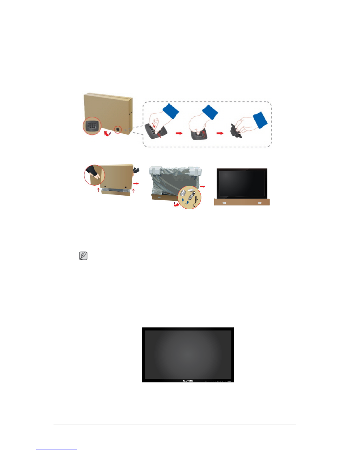
Checking the Contents of the Package
Remove the lock from the package box, as shown in the figure above.
Lift up the package box by
holding the grooves on both
sides of the package box.
Check the contents of the
package.
Remove the Styrofoam and
vinyl cover.
Note
•
After unpacking the package, make sure to check the contents of the package.
•
Store the packaging box in case you need to move the Product later.
• If any items are missing, contact your dealer.
• Contact a local dealer to purchase optional items.
Unpacking
LCD Display
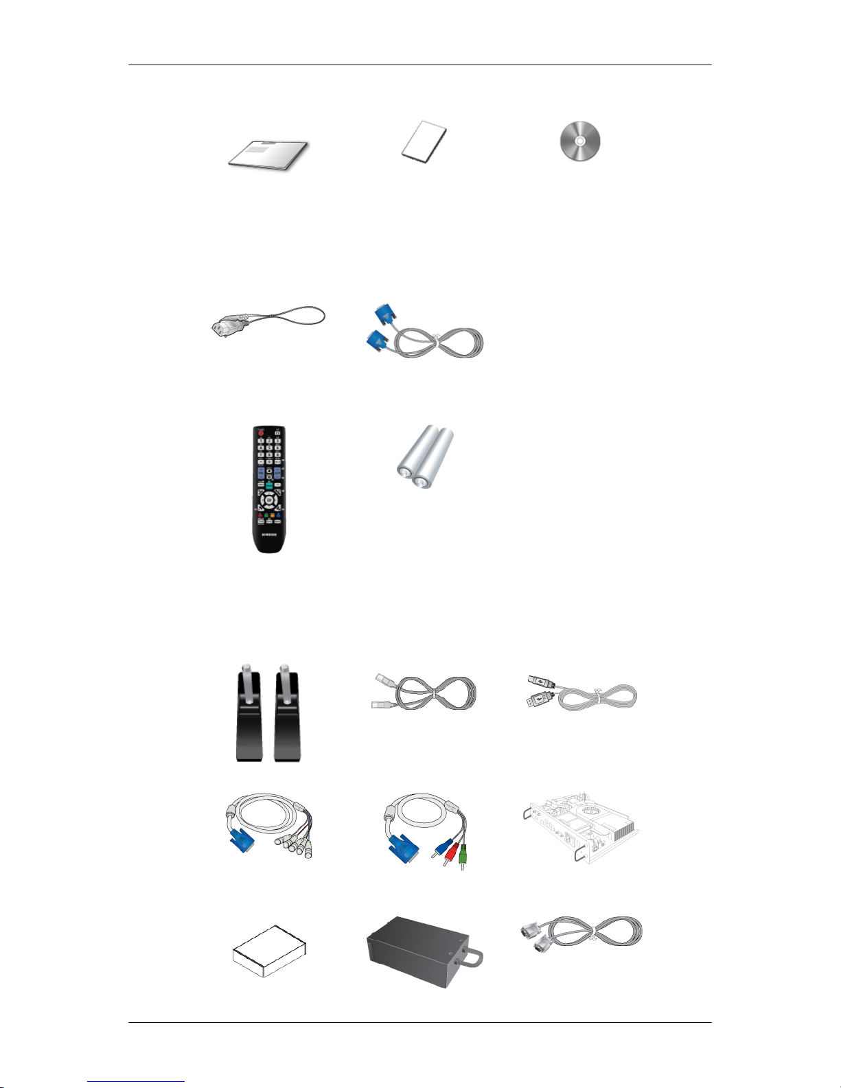
Manuals
Quick Setup Guide Warranty Card
(Not available in all loca-
tions)
User's Guide
Cables
Power Cord D-Sub Cable
Others
Remote Control
(BP59-00138B)
Batteries (AAA X 2)
(Not available in all loca-
tions)
Sold separately
Semi Stand KIT LAN Cable USB Cable
RGB to BNC Cable RGB to COMPONENT Ca-
ble
Network Box
Introduction
Sold separately
Wall Mount KIT TV Tuner box RS232C Cable
Your LCD Display
The color
and the appearance may differ depending on the product, and the specifications are subject
to change without prior notice to improve the performance.
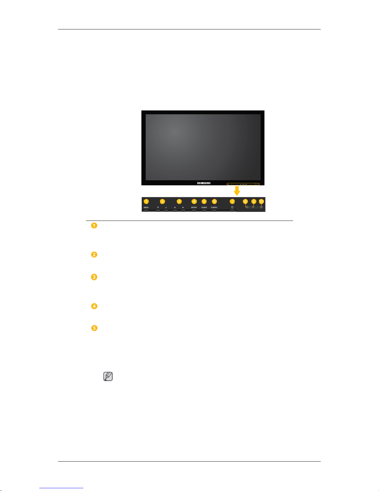
Front
MENU button [MENU]
Opens the
on-screen menu and exits from the menu. Also use to exit the OSD menu
or return to the previous menu.
Navigate buttons (Up-Down buttons)
Moves from
one menu item to another vertically or adjusts selected menu values.
Adjust buttons (Left-Right buttons) / Volume buttons
Moves from one menu item to another horizontally or adjusts selected menu values. When OSD is not on the screen, press the button to adjust volume.
ENTER button [ENTER]
Activates a highlighted menu item.
SOURCE button [SOURCE]
Switches from PC mode to Video mode. Selects the input source that an external
device is connected to.
[PC] → [
DVI] → [AV] → [Component] → [HDMI1] → [HDMI2] → [Dis-
playPort] → [MagicInfo] →[TV]
Note
• The [RGB/COMPONENT IN] port is compatible with RGB (PC) and Component signals.
However, the picture may display abnormally if the connected external input
signal is different from the selected video signal.
• MagicInfo can only be enabled when a network box is connected.
• A TV tuner box (sold separately) must be connected to use the TV.
Introduction
D.MENU button
Opens the on-screen D.MENU.
Note
The D.MENU
button is activated when a TV tuner is connected and otherwise, the
PIP button is enabled.
PIP button
Push the PIP button to turn the PIP screen On / Off.
Power button [ ]
Use this button for turning the LCD Display on and off.
Brightness Sensor
Automatically detects the surrounding brightness.
Note
This function does not work for this LCD Display.
Power indicator
Shows PowerSaver mode by blinking green
Note
See PowerSaver
described in the manual for further information regarding power
saving functions. For energy conservation, turn your LCD Display OFF when it
is not needed or when leaving it unattended for long periods.
Remote Control Sensor
Aim the remote control towards this spot on the LCD Display.
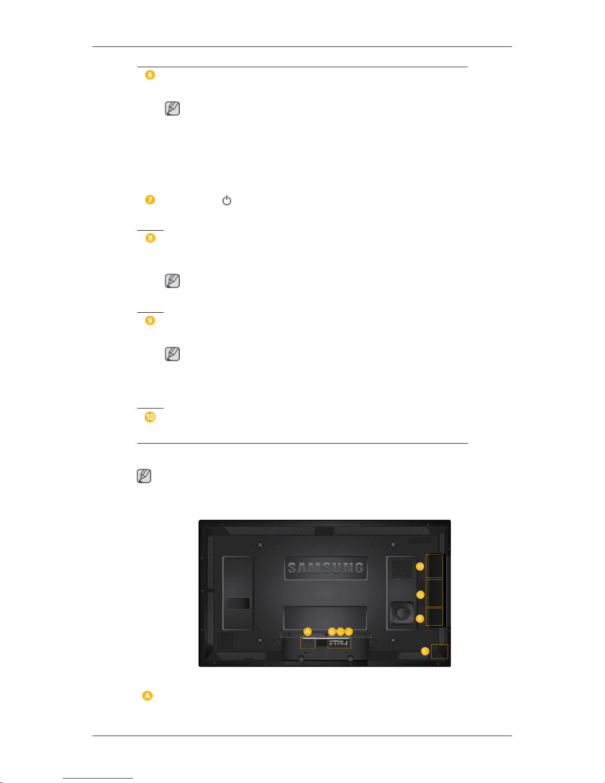
Rear
Note
See the
"Connections" section for details about cable connections. The LCD Display's configuration
at the back may vary slightly depending on the model.
Introduction
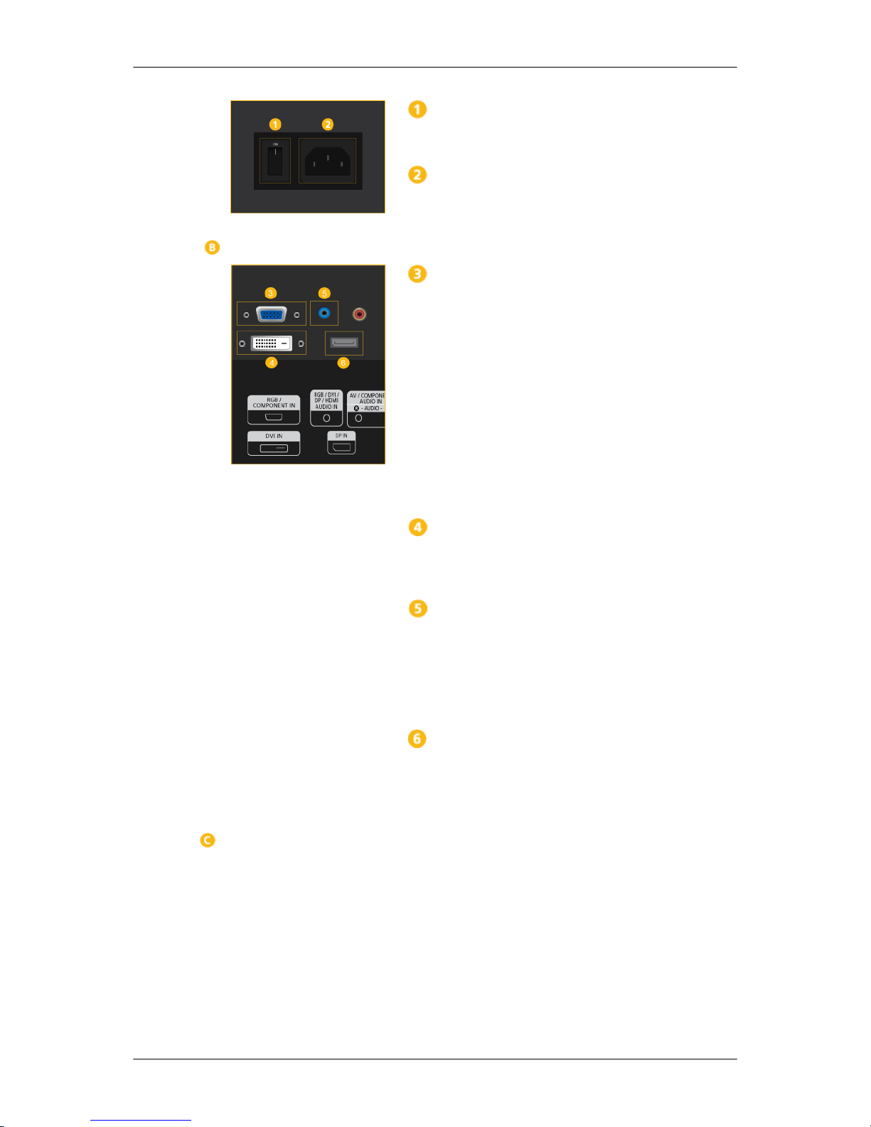
POWER S/W ON [
│
] / OFF
Switches the LCD Display On/Off.
POWER
The power
cord plugs into the LCD Display and
the wall outlet.
RGB/COMPONENT IN
(PC/COMPONENT
Connection Terminal (Input))
• Connect the [RGB/COMPONENT IN] port
on the monitor to the RGB port on the PC using the D-SUB cable.
• Connect the [RGB/COMPONENT IN] port
on the monitor to the COMPONENT port on
the external device using the RGB to COMPONENT cable.
• Connect the [RGB/COMPONENT IN] port
on the monitor to the BNC port on the PC using the RGB to BNC cable.
DVI IN (PC Video Connection Terminal)
Connect the [
DVI IN] port on the monitor to the
DVI port on the PC using the DVI cable.
RGB/DVI/DP/HDMI AUDIO IN (PC/DVI/
DP/HDMI Audio Connection Terminal (Input))
Connect the [
RGB/DVI/DP/HDMI AUDIO IN]
terminal of the monitor and the speaker output
terminal of your computer's sound card using a
stereo cable (sold separately).
DP IN
Receives a signal from the Display port.
Connect a
DP cable to [DP IN] on the product and
DP IN on another display.
Introduction
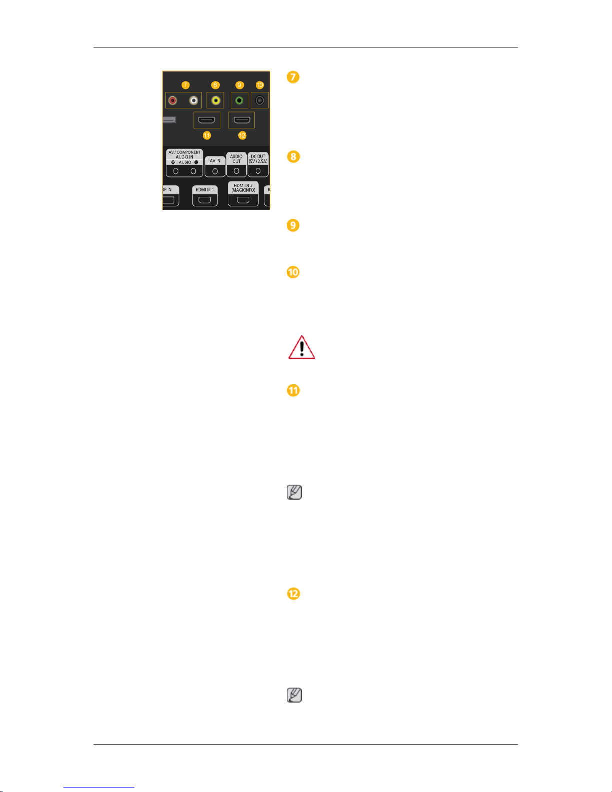
AV/COMPONENT AUDIO
IN [L-AUDIO-R]
Connect the [AV/COMPONENT AUDIO IN [LAUDIO-R]] port on the monitor to the audio
output port on the PC or on the external device
using an audio cable.
AV IN
Connect the [AV IN] terminal
of your monitor to
the video output terminal of the external device
using a VIDEO cable.
AUDIO OUT
Connect a headphone or an External speaker.
DC OUT
Make sure
to use connecting [DC OUT] terminal
to the authorized TV-Tuner Box[SBB_DTC/
ZA].
Otherwise, this may result in damage to
the product.
HDMI IN 1
• Connect the [
HDMI IN 1] terminal at the back
of your LCD Display to the HDMI terminal
of your digital output device using a HDMI
cable.
• Up to HDMI 1.3 can be supported.
Note
• A normal
external device (DVD player or
camcorder, etc.) or a TV tuner box can be
connected to the [HDMI IN 1] terminal.
• To use a TV tuner box, make sure to connect
it to the [HDMI IN 1] terminal.
HDMI IN 2 (MAGICINFO)
• Connect the [
HDMI IN 2 (MAGICINFO)]
terminal at the back of your LCD Display to
the HDMI terminal of your digital output device using a HDMI cable.
• Up to HDMI 1.3 can be supported.
Note
To use MagicInfo, the network box specified
separately by Samsung must be installed inside
Introduction

the product and the MagicInfo output
of the network box must be connected to the [HDMI IN 2
(MAGICINFO)] terminal.
For more information on how to purchase and install a network box, contact Samsung Electronics.
RJ 45 MDC (MDC PORT)
MDC(Multiple Display Control) Program Port
Connect the
LAN cable to [RJ45 MDC] on the
product and LAN on the PC. To use an MDC, the
MDC Program must be installed on the PC.
Note
Go to Multi
Control and select RJ45 MDC as
the MDC Connection.
RS232C OUT/IN (RS232C Serial PORT)
MDC(Multiple Display Control) Program Port
Connect a
serial cable (cross type) to [RS232C]
on the product and RS232C on the PC. To use an
MDC, the MDC Program must be installed on the
PC.
Note
Go to Multi
Control and select RS232C MDC
as the MDC Connection.
Kensington Lock slot
A Kensington
Lock is an anti-theft device that
enables users to lock the product so that they can
safely use it in public locations. Since the shape
and usage of the locking device may differ depending on the model and the manufacturer, for
more information, refer to the User Manual supplied with the locking device for more information.
Note
You must
purchase the Kensington Lock sepa-
rately.
To lock the product, follow these steps:
1. Wrap the Kensington lock cable around a
large, stationary object such as a desk or
chair.
Introduction
2. Slide the end of the cable with the lock at-
tached
through the looped end of the Ken-
sington lock cable.
3. Insert the Kensington Lock into the security
slot (
) on the back of the display.
4.
Lock the lock ( ).
Note
• These are
general instructions. For exact instructions, see the User Manual supplied with
the locking device.
• You can purchase the locking device from an
electronics store, an online shop, or our service Center.
Connecting a Network Box (sold separately)
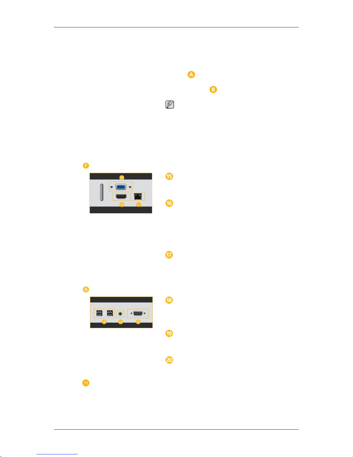
RGB OUT
MagicInfo video output port
MAGICINFO OUT
This is
the output terminal for the video, audio,
and control signals of MagicInfo.
It can be used by connecting it to the [HDMI IN
2 (MAGICINFO)] terminal using an HDMI cable.
LAN (LAN Connection Terminal)
Connects to
a LAN cable to allow Internet or net-
work access in MagicInfo mode.
Connecting a Network Box (sold separately)
USB (USB Connection Terminal)
Keyboard / Mouse, Mass Storage Device Compatible.
AUDIO OUT
Connect a headphone or an External speaker.
RS232C (RS232C Serial PORT)
Serial port
Connecting a Network Box (sold separately)
Introduction
 Loading...