

Samsung 400CX - SyncMaster - 40"" LCD TV, 400CXn - SyncMaster - 40"" LCD TV, 400CX-2, 400CXN-2, 460CX-2 Quick Start Manual
...
ii
LCD DISPLAY
quick start guide
400CX-2, 400CXN-2, 460CX-2, 460CXN-2
Introduction
Package Contents
Note
Please make sure the following items are included with your LCD Display.
If any items are missing, contact your dealer.
Contact a local dealer to buy optional items.
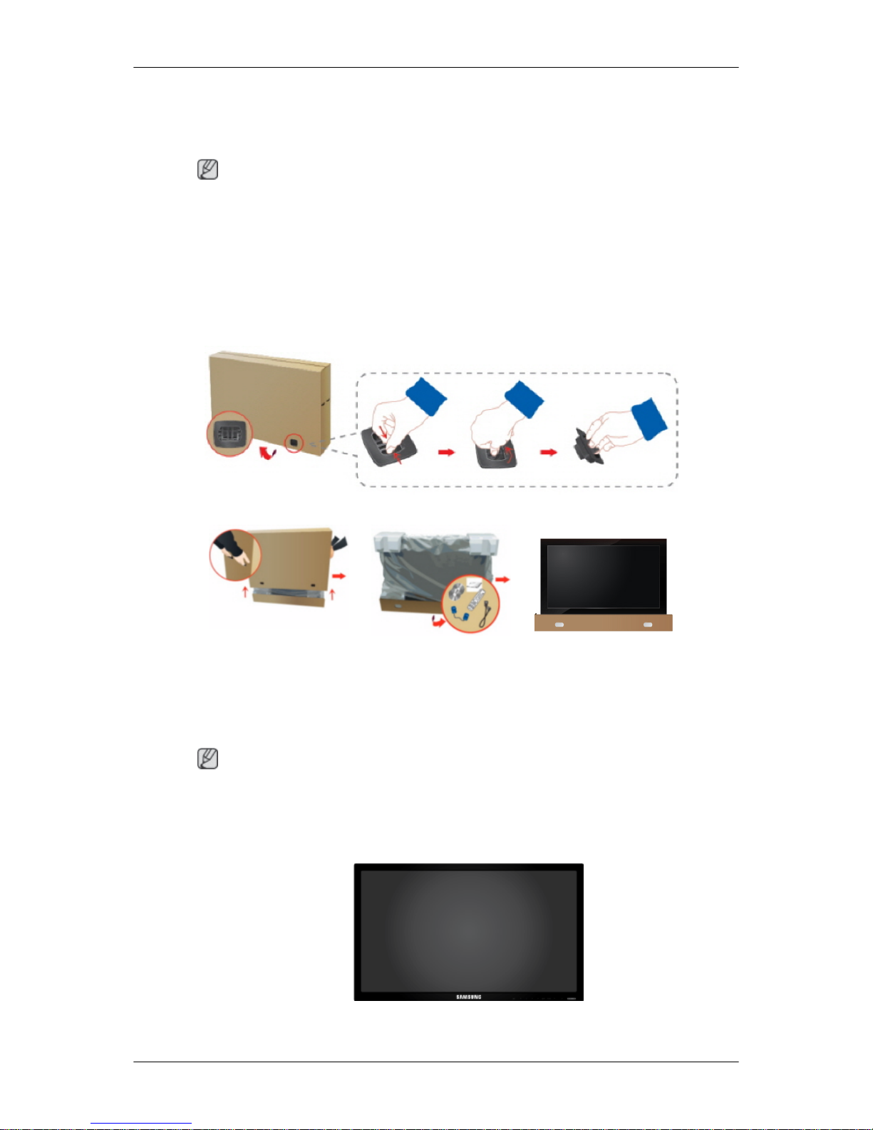
Checking the Contents of the Package
Remove the lock from the package box, as shown in the figure above.
Lift up the package box by
holding the grooves on
both sides of the package
box.
Check the contents of the
package.
Remove the Styrofoam
and vinyl cover.
Note
• After unpacking the package, make sure to check the contents of the package.
• Make sure to keep the package box for transporting the product in the future.
Unpacking
LCD Display
9
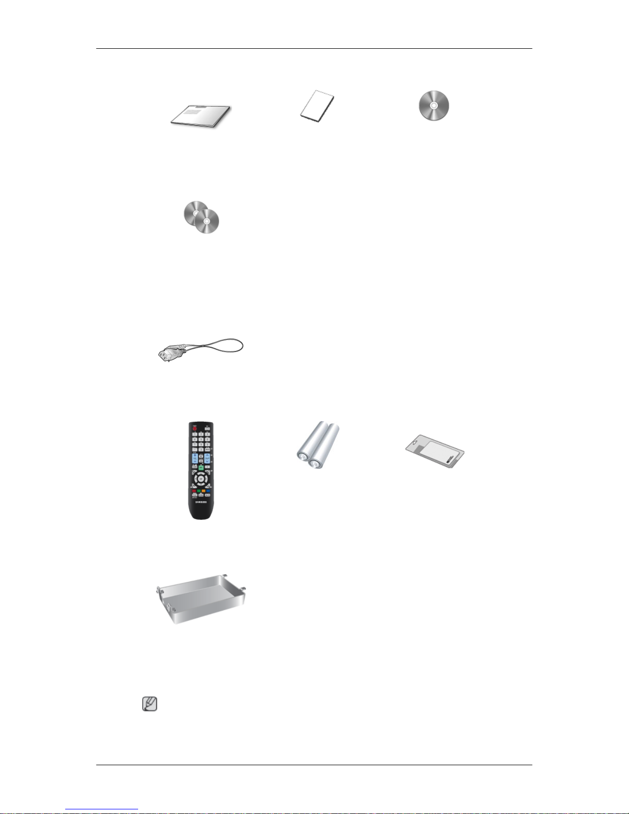
Manuals
Quick Setup Guide Warranty Card
(Not available in all loca-
tions)
User's Guide
MagicInfo Software CD,
MagicInfo Manual CD
(Applicable to the CXN-2
model only)
Cables
Power Cord
Others
Remote Control Batteries (AAA X 2)
(Not available in all loca-
tions)
Cleaning Cloth
HDD Cover
(Applicable to the CXN-2
model only)
Note
Cleaning Cloth is only provided for highly polished black products as a product feature.
Introduction
10
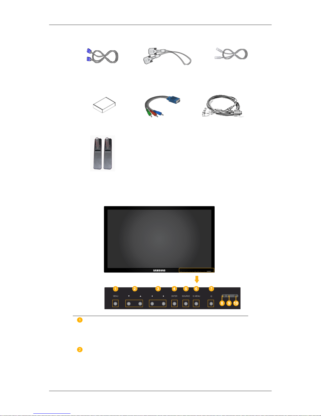
Sold separately
D-Sub Cable DVI Cable LAN Cable
(Applicable to the CXN-2
model only)
Wall Mount KIT Component to D-sub Ca-
ble
D-sub / BNC Cable
Semi Stand KIT
Your LCD Display
Front
MENU button [MENU]
Opens the on-screen menu and exits from the menu. Also use to exit the
OSD menu or return to the previous menu.
Navigate buttons (Down-Up buttons) / Channel buttons
Moves from one menu item to another vertically or adjusts selected menu
values.
/ When OSD is not on the screen, press the button to adjust channels.
Introduction
11
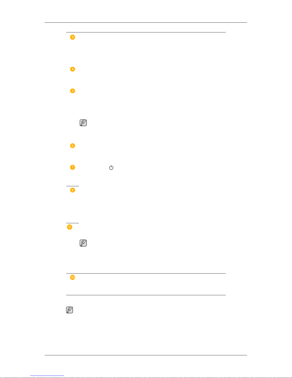
Adjust buttons (Left-Right buttons) / Volume buttons
Moves from one menu item to another horizontally or adjusts selected
menu values. When OSD is not on the screen, press the button to adjust
volume.
ENTER button [ENTER]
Activates a highlighted menu item.
SOURCE button [SOURCE]
Switches from PC mode to Video mode. Selects the input source that an
external device is connected to.
[PC] → [DVI] → [AV] → [Component] → [HDMI] → [MagicInfo] → [TV]
Note
MagicInfo supports the CXN-2 model only.
D.MENU
Opens the on-screen D.MENU.
Power button [ ]
Use this button for turning the LCD Display on and off.
Brightness Sensor
(Optional)
Automatically detects the surrounding brightness.
This function is activated only on the models equipped with an auto brightness sensor.
Power indicator
Shows PowerSaver mode by blinking green
Note
See PowerSaver described in the manual for further information regarding
power saving functions. For energy conservation, turn your LCD Display
OFF when it is not needed or when leaving it unattended for long periods.
Remote Control Sensor
Aim the remote control towards this spot on the LCD Display.
Rear
Note
For detailed information concerning cable connections, refer to Connecting Cables under
Setup. The LCD Display 's configuration at the back may vary slightly depending on the model.
Introduction
12
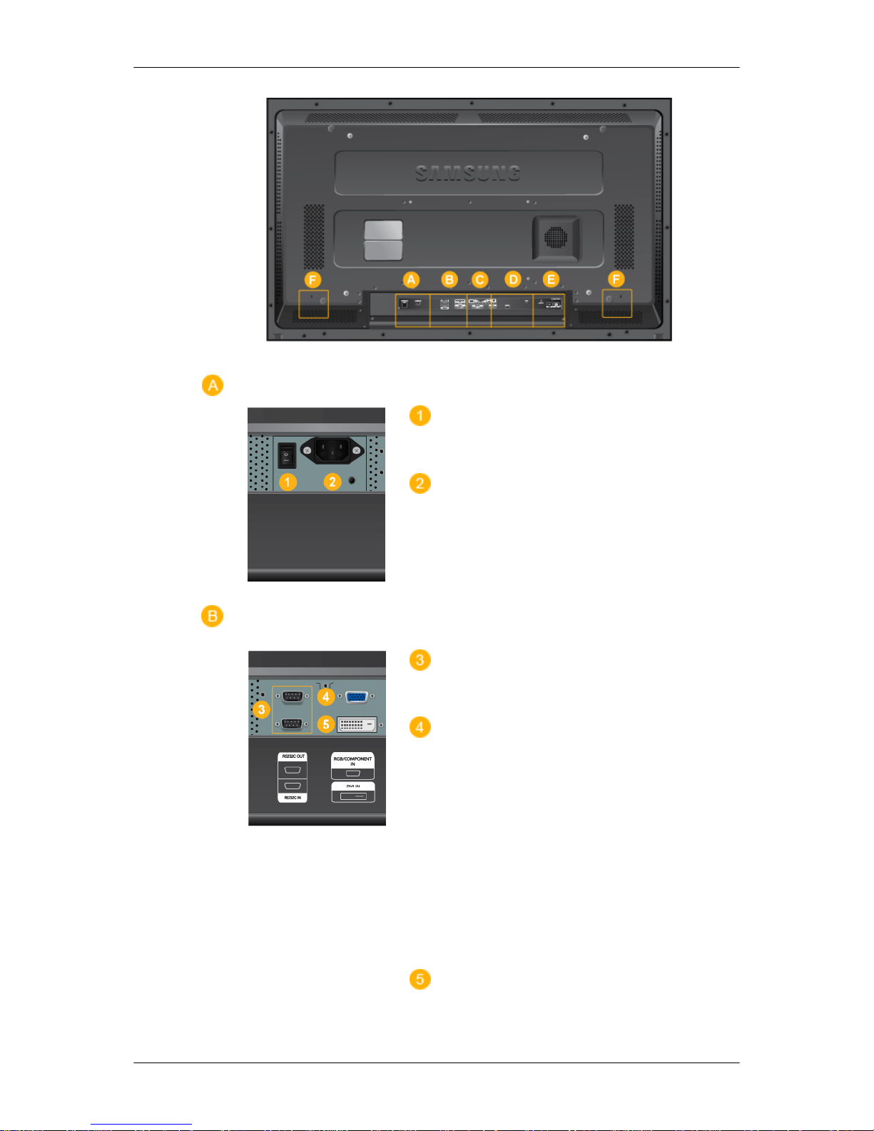
POWER S/W ON [ │ ] / OFF [O]
Switches the LCD Display On/Off.
POWER
The power cord plugs into the LCD Display
and the wall outlet.
RS232C OUT/IN (RS232C Serial PORT)
MDC(Multiple Display Control) Program Port
RGB/ COMPONENT IN (PC Video Con-
nection Terminal)
• Use a D-Sub Cable (15 pin D-Sub) - PC
mode (Analog PC)
• Connect the RGB/COMPONENT IN port
on the monitor to the COMPONENT port
on the external device using the D-SUB
to COMPONENT cable.
• Connect the RGB/COMPONENT IN port
on the monitor to the BNC port on the PC
using the D-SUB to BNC cable.
DVI IN (PC Video Connection Terminal)
Introduction
13
Use a DVI Cable (DVI-D to DVI-D) - DVI
mode (Digital PC)
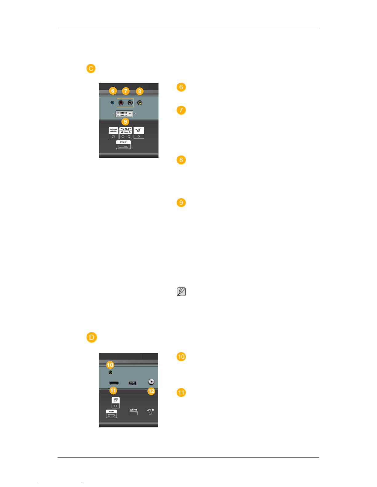
DVI / RGB AUDIO IN (PC/DVI/Audio
Connection Terminal (Input))
AV / COMPONENT AUDIO IN [R- AU-
DIO- L]
Connect the port of the DVD, VCR (DVD /
DTV Set-Top Box) to the [ R- AUDIO - L ] port
of the LCD Display.
AV IN [VIDEO]
Connect the [ VIDEO ] terminal of your monitor to the video output terminal of the external device using a VIDEO cable.
DVI OUT
• Connect a monitor to another monitor
through a DVI cable.
• Connect the DVI OUT port on the monitor
to the HDMI IN port on the other monitor
using the DVI to HDMI cable.
• DVI, HDMI and network signals sent via
the DVI OUT port are displayed on the
second display which has the DVI IN port.
Note
Up to 6 Full HD or 10 HD monitors can be
connected (May differ depending on the
product).
AUDIO OUT
Headphone/External speaker output terminal.
HDMI IN
Connect the HDMI terminal at the back of
your LCD Display to the HDMI terminal of
your digital output device using a HDMI cable.
Up to HDMI cable 1.0 can be supported.
Introduction
14
ANT IN
Connect the CATV cable or TV antenna cable to the " ANT IN" port on the rear side of
the LCD Display. Make sure to use a TV antenna cable (sold separately) as the antenna
cable.
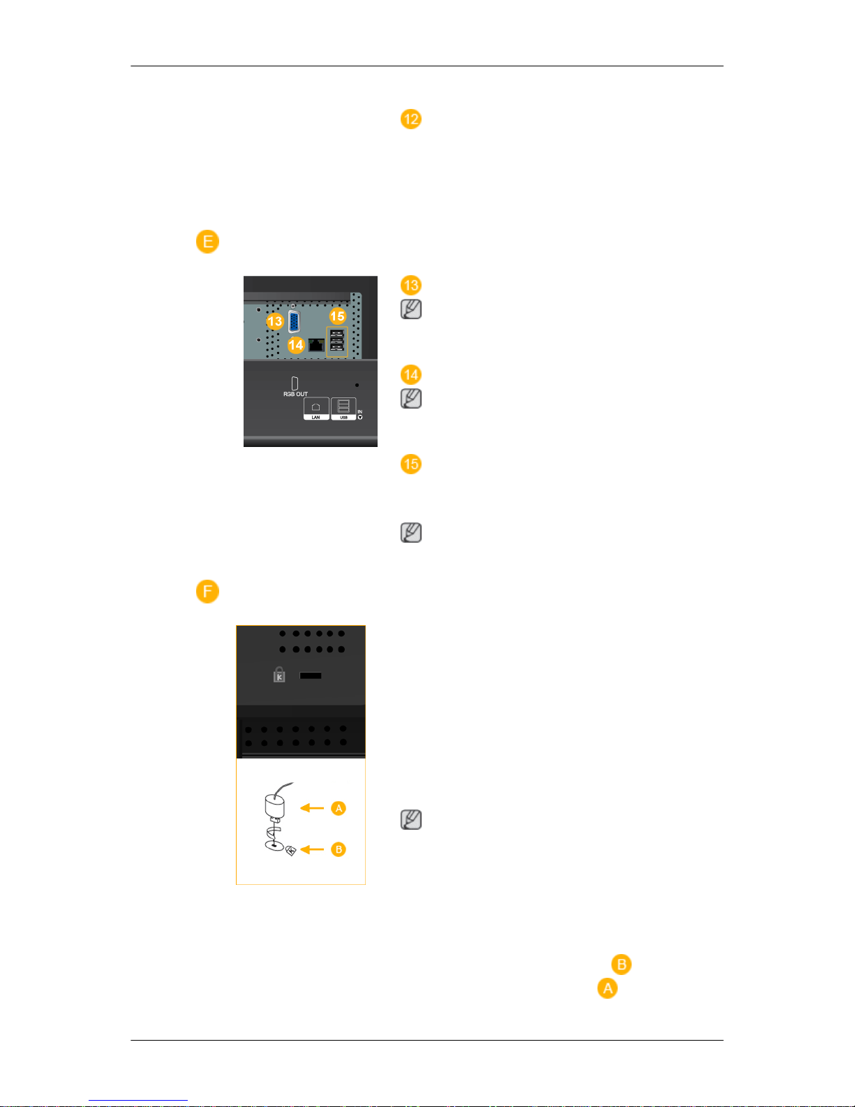
RGB OUT
Note
(Applicable to the CXN-2 model only)
LAN (LAN Connection Terminal)
Note
(Applicable to the CXN-2 model only)
USB(USB Connection Terminal)
Keyboard / Mouse, Mass Storage Device
Compatible.
Note
(Applicable to the CXN-2 model only)
Kensington Lock
The Kensington Lock is a device used to
physically fix the system when using it in a
public place. The locking device has to be
purchased separately. The appearance and
locking method may differ from the illustration depending on the manufacturer. Refer to
the manual provided with the Kensington
Lock for proper use. The locking device has
to be purchased separately.
Note
The location of the Kensington Lock may be
different depending on the model.
Using the Anti-Theft Kensington Lock
1. Insert the locking device into the Ken-
sington slot on the LCD Display and
turn it in the locking direction .
Introduction
15
 Loading...