

Samsung RC090-120-140, 160MHXEA Installation And Maintenance Manual

www.samsungehs.co.uk ©G Hendra April 2015 1
Installer
Please
Read
Instructions
Inside

www.samsungehs.co.uk ©G Hendra April 2015 2
www.samsungehs.co.uk ©G Hendra April 2015 3
Air Source Heat Pump
Installation and Maintenance Manual
Model Numbers:
RC090-120-140 and 160MHXEA
www.samsungehs.co.uk ©G Hendra April 2015 4
The outdoor unit (boiler)
Deciding on Where to Install the Outdoor Unit
Choose a location where the noise of the Air to Water Heat Pump when running and the
discharged air do not disturb any neighbours.
Install the outdoor unit on a flat, stable surface with plenty of drainage, gravel or grass is
ideal; make sure the base can support its weight
Position the outdoor unit so that the air flows into an open area, where there are no plants
and animals
If you can see the sea from the position of the outdoor unit you need to apply Blygold, Bronze
glow or equivalent anti-corrosion coating on the whole unit.
The unit will not benefit from being mounted on the North or south of the building, any aspect
is fine, you should avoid very exposed positions to avoid wind blowing into the back or front of
the unit.
The unit needs to be securely
mounted at least 100mm off the
ground on rubber feet. The unit
must be bolted down for security
using 10mm bolts and Zebedee
bolts. If wall brackets are used we
recommend 600mm unistrut
cantilever arms are used. Caution
should be applied when wall
mounting because any vibration
form the unit can be transmitted into the
wall creating noise.
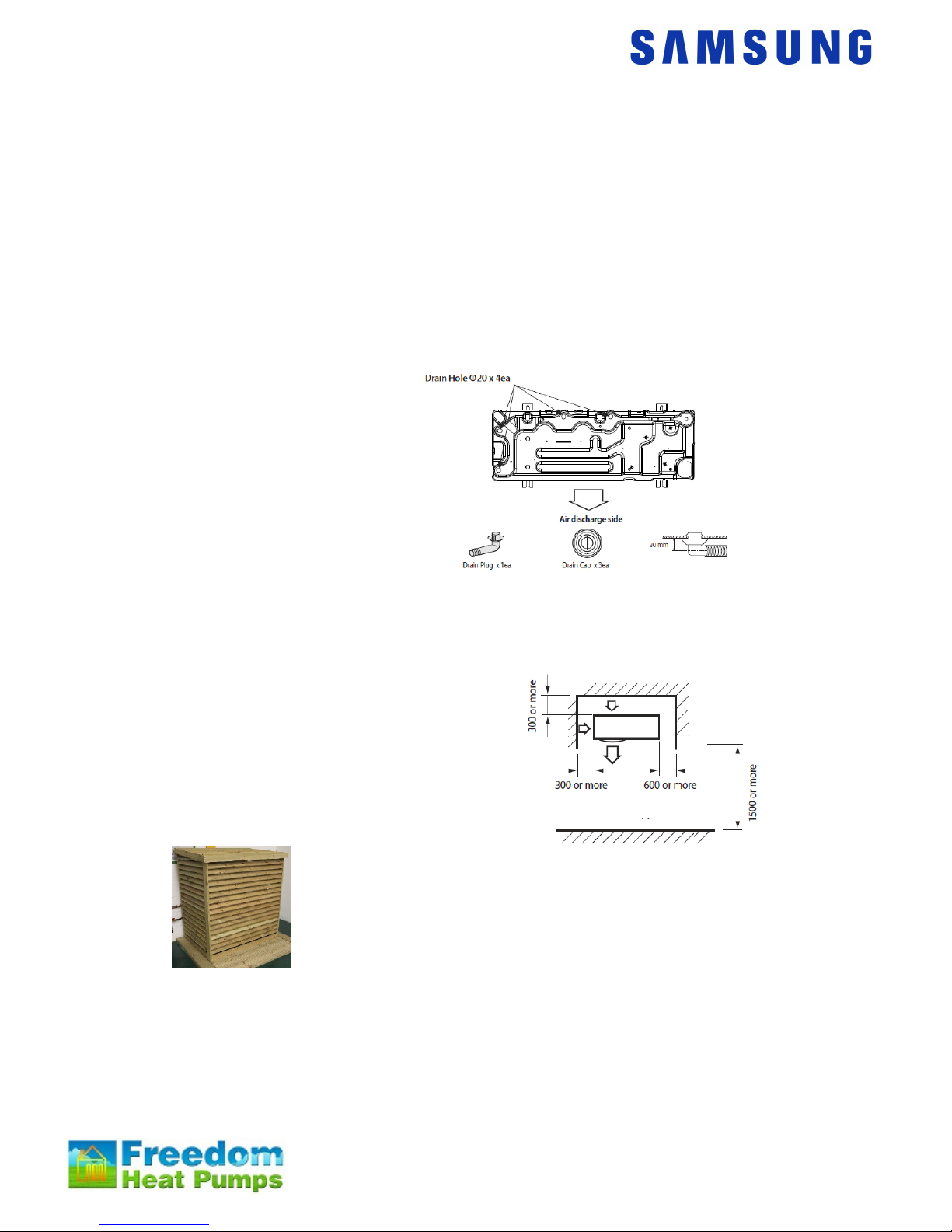
The unit must have adequate drainage away from the unit; it can produce up to 6 L / hour.
There is a drainage kit included which we recommend you don’t use, its best to let the unit
drain into the ground. If a drip tray is used it must be 25mm longer and wider than the base of
the unit to catch all the drips.
Dimensions:
Size 16 - 1420mm (h) 940mm (w) 330mm (d) 103kg
Size 9 - 998mm (h) 940mm (w) 330mm (d) 75kg
The space around the unit is very important, allow:
300mm to the left hand side (facing the front of the
unit), 600mm to the right of the unit, 300mm to the
rear of the unit and 1500mm to the front of the unit.
Wooden enclosures are now available for the units, please contact your
distributor for details.
The Control Box
When the heat pump is delivered it comes with a control box which also contains the flow
switch. Install the control unit indoors as it’s not waterproof.
It needs to be sited less than 15m of the hot water cylinder, 100m of the outdoor unit and as
near as possible to the pump, flow switch and any zone valves.
The box is 323mm wide, 339mm high, 131mm deep
www.samsungehs.co.uk ©G Hendra April 2015 5
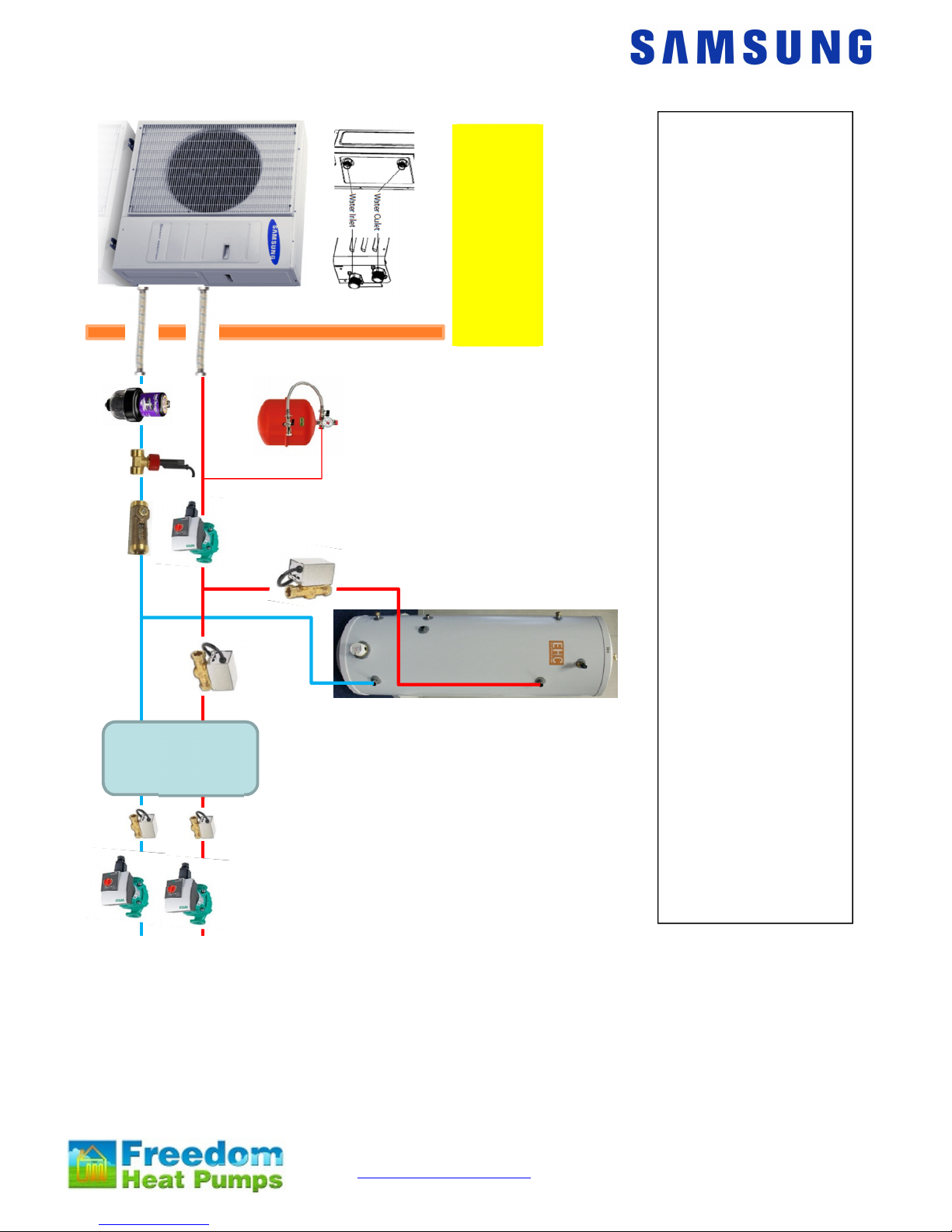
Pipework Schematic size 9 and 16 units
The heat pump has 1 inch
BSP male connections;
these should be
connected to flexi hoses.
The flexi hoses have to be
insulated to conform to
MCS.
To maintain flow rate we
recommend 28mm
pipework is used with this
machine. NEVER use
22mm plastic tube, if you
insist on using plastic use
28mm throughout
You will also need to
install:
High resistance pump,
Expansion vessel,
Pressure gauge,
Pressure relief valve,
Filling loop,
Magnetic filter
Strainer.
Flow meter
Flow switch
2 x 2 port valves
We recommend the
system has a break in it,
you can use a header, a
buffer or a heat exchanger
to do this. This is done to
maintain uninterrupted
flow.
The domestic hot water
cylinder must be
manufactured specifically
for the heat pump and
have a coil with a surface
area of 3m^2 equivalent.
For more details see next
page
Standard System With Header
Or Buffer And 2 Ports
To keep pump sizes
down we recommend
28mm pipework for the
main runs
The header or buffer is in the
heating part of the circuit only.
You can have as many heating
zones as you like, we have only
shown 2. Each zone needs its
own pump and valve.
Pumps 2 and 3 only run when
there is a heating demand, they
are driven by the external run
signal form under floor manifold
or stat.
Header
, buffer
or heat
exchan
ger
Pump 1
Pump 2 Pump 3

www.samsungehs.co.uk ©G Hendra April 2015 6
Other components you need to supply and fit:
An expansion vessel, pressure gauge, pressure relief valve and filling
loop
Most heating engineers use a robokit with the appropriate size expansion
vessel; this is sized exactly the same way as when using a boiler.
Pump
Your pump needs to supply 20l/min for the 9kW and 30l/min for the 16kW unit.
The static resistance through the unit is 10kPa for the 9kW and 15kPa for the
16kW unit. The flow meter has a resistance of around 5kPa
The cylinders (Gledhill) have a static resistance of 5kPa for the heat pump coil
and 19kPa for the solar coil.
The total resistance of the components will be approximately 39kPa for the size
9 unit and if the cylinder is piped using both coils and approximately 44kPa for the size 16
unit.
Flow switch and flow meter
The unit requires 17L / min flow at all times, if you don’t achieve this
E911 error will occur to check this flow switch is installed. The flow
switch comes with the control box.
The flow Switch MUST be installed in either horizontally or vertically
with at least 150mm of straight pipe either side, connection is 1” female BSP. The wire is 2m
long and needs to connect into the wiring station. This wire can be extended to suit. We
recommend a flow meter is installed into the flow side of the flow switch as per the photo.
Adaptors may be required to enable this join. The flow switch is not IP65 rated (weatherproof)
and so must not be installed externally.
Diverter valves
If you require domestic hot water and heating, diverter valves are required, you
need to supply these.
Water Filter
In all cases a filter with strainer needs to be installed in the return to the heat pump. A
magnetic filter must also be installed in the return to the unit. The filters ensure that
debris/foreign materials do not cause damage to the heat exchanger in the unit voiding
warranties.
Glycol
A propylene glycol mixture must be utilized to prevent freezing of the water within the system.
It is important that the glycol concentration is adequate to protect the unit in case of power
failure in very cold conditions. If the unit freezes up there will be no warranty. Manufacturer
dependant, a mix of around 25% should suffice.
Buffer vessels, heat exchangers and low loss headers
You don’t have to use a buffer vessel on a Samsung but we do need a minimum flow rate of
17l/min and have a circulating volume of over 20 Litre. To achieve this is much easier if you
break the system in two with a header, a buffer or a heat exchanger.
Bypass Valve
If you don’t use a header buffer or heat exchanger you must install a bypass
valve in the heating circuit as far away from the heat pump as possible. The
bypass valve enables flow to be maintained as the trv’s shut down at all times to
prevent unit flow fault.
The Cylinder:
The cylinder needs to be installed less than 15m from the control box to allow for the
temperature sensor cable. Note the size and weight of the cylinder. Full installation
instructions are included with the cylinder.
Cylinders can be used IF the coil area is more than 2.5m^2. Smaller coils are not acceptable
and cannot be used. Please do not attempt to utilize a standard central heating, non-heat
pump optimized cylinder. Cylinders can be pressurised or open vented.
www.samsungehs.co.uk ©G Hendra April 2015 7
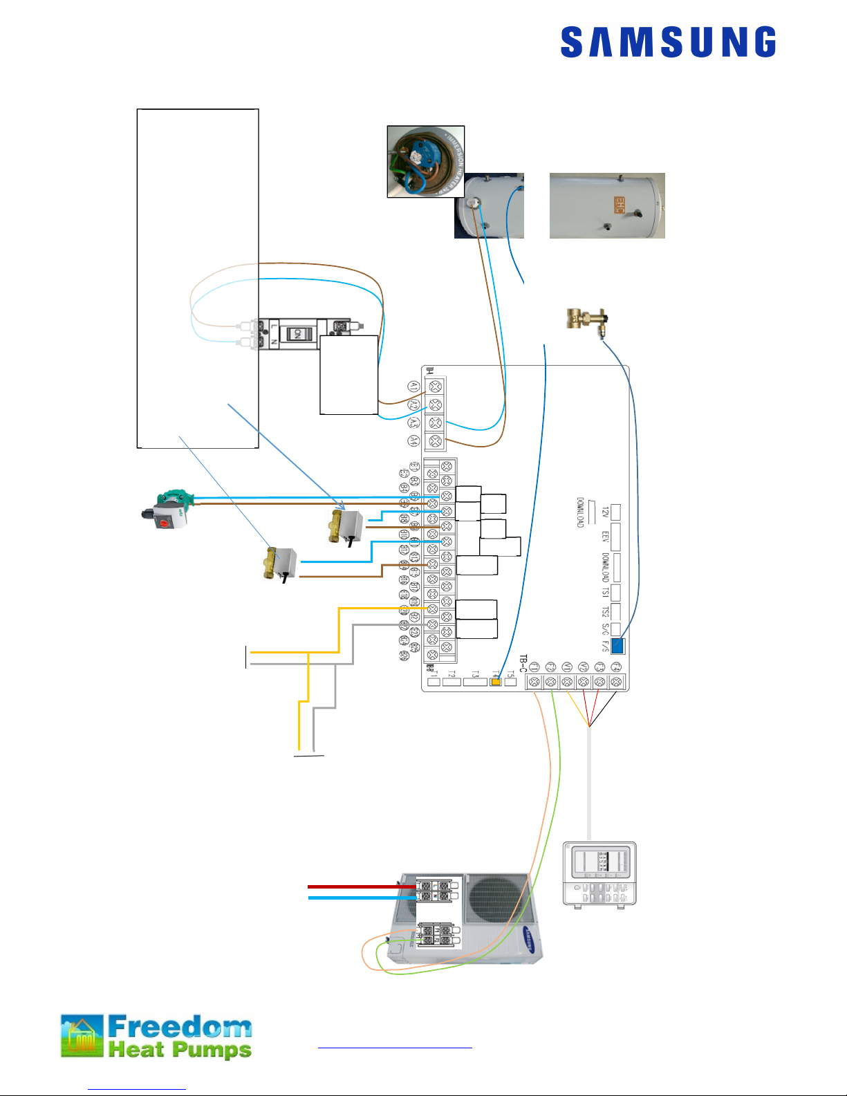
Wiring diagram for heating and HW heat pump:
Flow switch 2m long
you can extend this
Standard System
With Header Or Buffer
and 2 Ports
Power
input
16Amps
Power supply
240V
20A for size 9
32A for size 16
Communication
cable 2 core 1mm
(16Vdc)
12m long
Hot
water
valve
Valve
zone 1
How the valves work
The HW valve is only open (B9 live) when the system is in
HW mode (coke can symbol showing in status on controller)
it is closed (B10 live) at all other times.
Heating valve 1 is open at all times (B14 live) except when
HW is operating and when thermostat 2 only is made, (B13
live).
Pump 1
Fl
ow switch 2m long
you can extend this
Run signal
from
heating
zone
valves
Run signal
from
heating
zone
valves
5
6
1
1
9
1
4
2
0
2
2
7
Tank sensor 15m long DON
’
T cut this
 Loading...